F6OBSM170BStadiometer
InBody Co., Ltd.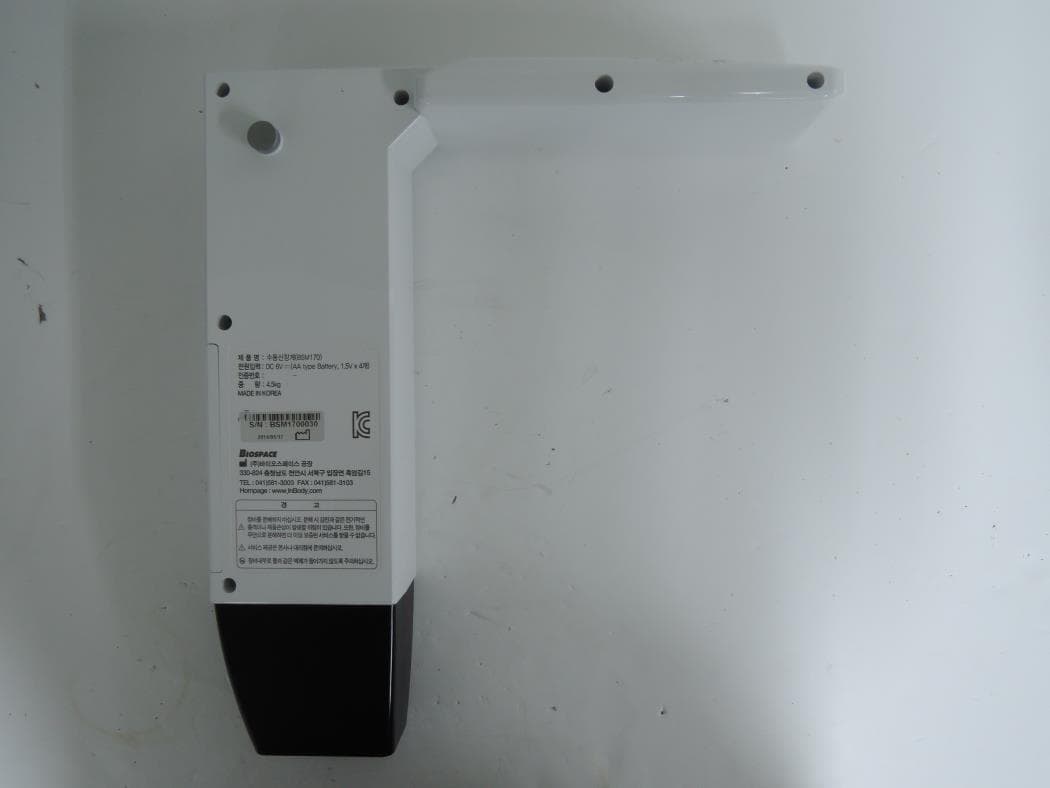
Click to zoom
Application Details
- Equipment Class
- DSS - Part 15 Spread Spectrum Transmitter
- Date of Grant
- Sep 24, 2014
- Application Purpose
- Original Equipment
- Date of Application
- Sep 24, 2014
- Equipment Note
- Stadiometer
- Frequency Range
- 2402.00000000 - 2480.00000000
- Company
- InBody Co., Ltd.
- Country
- South Korea
Documents & Files
Document Text
Text extracted from the exhibit documents filed with the FCC. Open a document above to read the original.
Users Manual
User's Manual ⓒ 2014 InBody Co., Ltd. All rights reserved. BM-ENG-E9-B-140827 For any problems with BSM170/170B or any clinical questions, please contact us at the following: InBody Co., Ltd. [HEAD OFFICE] InBody Bldg., 54, Nonhyeon-ro 2-gil, Gangnam-gu, Seoul, Korea TEL: +82-2-501-3939 FAX: +82-2-578-2716 W ebsite: http://www.inbody.com E-mail: [email protected] Reproduction, adaptation, or translation of this manual is prohibited without prior written consent from InBody Co., Ltd under the copyright laws. This manual might have typographical errors, and its content can be changed without a prior notice. InBody Co., Ltd. shall not be liable for any errors, incidental, or consequential damages that occurred by not complying with the content of the User's Manual. Visit our website http://www.inbody.com to view and download further information about the functions of the BSM170/170B, the explanation of results output, and more. InBody Co., Ltd reserves the right to modify the appearance, specifications, and etc. of the BSM170/170B to improve the quality of the product, without prior notice for reasons of performance improvement. Please note the important information below before reading this manual. Failure to comply with safety warnings and regulations can cause serious injury or death. DANGER NOTECAUTION 참 조주 의 Failure to comply with safety cautions and regulations can cause injury or property damage. DANGER NOTECAUTION 참 조주 의 Warning Caution Customer Service Information InBody USA [USA] 13850 Cerritos Corporate Dr., Unit C, Cerritos, CA 90703, USA TEL: +1-323-932-6503 FAX: +1-323-952-5009 Website: http://www.inbodyusa.com E-mail: [email protected] InBody Japan Inc. [JAPAN] Second Floor Ayabe Bldg., 2-17-3 Sotokanda, Chiyoda-ku, Tokyo JAPAN TEL: +81-03-5298-7667 FAX: +81-03-5298-7668 Website: http://www.inbody.co.jp E-mail: [email protected] EU Representative. [EUROPE] DongBang Acuprime. 1 Forrest Units, Hennock Road East, Marsh Barton, Exeter EX2 8RU, U.K TEL: +44-1392-829500 FAX: +44-1392-823232 Website: http://www.inbody.com E-mail: [email protected] Biospace China. [CHINA] 904, Xing Di Plaza, No. 1698 Yishan Road, Shanghai, 201103, CHINA TEL: +86-21-64439738, 9739, 9705 FAX: +86-21-64439706 Website: http://www.biospacechina.com E-mail: [email protected] Australian Sponsor. [AUSTRALIA] Emergo AUSTRALIA. Level 20, Tower II, Darling Park, 201 Sussex Street, Sydney, NSW 2000, AUSTRALIA TEL: +61-2-9006-1662 FAX: +61-2-9006-1010 Website: http://www.emergogroup.com E-mail: [email protected] I. Stadiometer Installation A. Product Components B. Operating Environment C. Installation Instructions D. Stadiometer Settings E. Maintenance II. Height Measurement A. Precautionary Measurements B. Measurement Instructions C. Measurement Posture III. T ransportation and Storage A. Repacking Instructions B. Transportation and Storage Environment IV. Fr equently Asked Questions V. Others A. Exterior and Functions B. Symbols C. Specifications 4 5 5 12 18 19 20 21 22 22 23 24 26 27 User’s Manual Contents 4 I. Stadiometer Installation A. Product Components The BSM170/170B contains of the following components. Make sure all of the following components are present. * Please inspect each component of the BSM170/170B for damage prior to installation. ❶ Footplate 1 EA ❷ Stand (upper) 1 EA ❸ Stand (lower) 1 EA ❹ Measurement unit 1 EA ❺ Measurement tape 1 EA ❻ Footplate mounting screws 4 EA ❼ Stand mounting screws 8 EA ❽ User’s manual 1 EA ❾ AA batteries 4 EA ❿ Test Jig 1 EA ❹ ➒ ➓ ❺ ❻ ❼ ❷ ❸ ❶ ➑ 5 2. Insert the “Stand (lower)” into the footplate, ensuring that the arrow ( ▼ ) located on the bottom right of the “Stand (lower)” and the arrow ( ▲ ) located on the footplate face one another. * When inserting into the “Stand (lower)”, part without screw holes must face downward. * The “Stand (lower)” and the footplate are designed to be assembled together in only one particular direction. Forcing the stand to be inserted in other directions could damage the product. B. Operating Environment Please make sure that the environment is adequate for the BSM170/170B installation. This equipment is designed for indoor use. If installing outdoors, the following requirements must be fulfilled. Temperatures range 10 ~ 40°C (50 ~ 104°F) Relative humidity30 ~ 75% RH Atmospheric pressure70 ~ 106kPa • Before installing BSM170/170B, check that the ceiling is at least 2.3 m high. The maximum height of this equipment is 2.19m. Keep a space of at least 3cm between the ceiling and the top of the BSM170/170B. DANGER NOTECAUTION 참 조주 의 Warning C. Installation Instructions 1. After opening the BSM170/170B box, remove the packaging materials and take all product components out. • Keep the packaging materials provided for repacking the equipment in the future. Other wastes should be disposed of according to relevant laws and regulations. • Install the BSM170/170B on a leveled, non-vibrating surface. Installing the equipment on an uneven surface may cause the examinee to fall down. Measurement results may also be inaccurate. • Never clean the BSM170/170B with liquid spray or detergent directly. The equipment may corrode and/or malfunction if the liquid or detergent leaks inside. Additionally, BSM170/170B measurement tape may be damaged. W hen cleaning the BSM170/170B, gently wipe it with the cloth. DANGER NOTECAUTION 참 조주 의 Warning 6 3. Hold the “Stand (lower)” in place to prevent it from sliding out of the insertion hole of the footplate, tilt the equipment sideways towards the floor. 4. Screw each of the 4 footplate leveling screws into the holes located on the opposite side of the stand insertion hole of the footplate. 5. Tighten the Stand mounting screws by turning them clockwise with the Phillips screwdriver. 7 6. Once all four screws as fastened tightly, return the “Stand (lower)” and footplate to an upright position. 7. Insert the black end of “Stand (upper)” into the “Stand (lower)” as illustrated below. • Hold the “Stand …
Text truncated - open the document above for the full version.
Users Manual
14 4) Unit: Units used for measurement. a. Use the button to move to ‘Unit’ and then press the button. b. Use the button to set the unit appropriate for the test environment. * Unit can be set to be cm or feet and inches. Unit setup c. Save changes by pressing the button. 6) After configuring the BSM170/170B, press the button to move to ‘Exit’ and press the button. BSM170/170B is now ready for use. Offset value setup 5) Offset value: Setting an offset value allows height measurements to be adjusted automatically. a. Use the button to move to ‘Offset’ and then press the button. b. Move the measurement unit up or down to set an offset value appropriate for your test environment. * Offset value can be set up to ±99.9cm. * To reset the offset value to 0.0, press the button. c. Save changes by pressing the button. 15 2. Optional Settings 1. After turning on the BSM170/170B, press and hold the button and the button on the measurement unit simultaneously for at least 3 seconds to enter the Setup menu. 2. In the Setup menu, you can calibrate the equipment or reset factory default settings. 1) Calibration: The equipment can be calibrated to ensure correct measurement values. a. Raise the measurement unit to eye level as illustrated below . * The measurement unit should be at least a minimum of 92 cm off the footplate. Right scales Left scales Calibration setup b. Use the button to move to ‘Cal.’ and then press the button. 16 e. The number ‘34.3’ appears on the LCD screen. c. Use the button to move to ‘Yes’ and then press the button. Calibration will begin. d. Lower the measurement unit all the way down of the footplate and press the button. * The measurement unit must be lowered until it is resting against the footplate. 17 g. Erect the Test Jig provided at the logo on the footplate and lower the measurement unit so that it touches the top of the Test Jig as illustrated below. * The Test Jig must be positioned perpendicular to the footplate. * The Test Jig must be positioned correctly. f. Press the button to move to ‘Exit’ and then press the button. BSM170/170B is now ready for use. 18 h. Check that the ̒ 88.9cm ̕ is shown on LCD screen of the measurement unit. * If ̒ 88.9cm ̕ is not shown on the LCD screen(error range: ±0.1cm), please contact InBody. Reset 2) Reset: Reset all settings to factory settings. a. Use the button to move to ‘Reset’ and then press the button. b. Use the button to move to ‘Yes’ and then press the button. All stored settings will be reset. E . Maintenance DANGER NOTECAUTION 참 조주 의 Caution • It may not be possible to take any measurements if the measuring tape has been damaged or dirtied. • It may not be possible to take any measurements if there is an excessive amount of shock placed on the measurement unit. • The screw adjusting movement of the measurement unit along the Stand may be loosened according to environmental changes and usage duration. Use the pressure adjusting screw on the rear of the measurement unit to adjust the pressure appropriately. • Use batteries made by the same manufacturer. • Do not lean on the Stand or apply excessive shock to it. • When storing the BSM170/170B, remove the batteries and repackage. 19 II. Height Measurement A. Precautionary Measurements DANGER NOTECAUTION 참 조주 의 Warning/Caution • If the equipment is unstable or unbalanced when you step on the footplate, use the footplate adjustment screws to ensure that the equipment is level before taking measurements. • Take care when lowering the measurement unit to not catch your fingers. • Do not run around run around or play around the footplate. This may result in serious injury. • Children and people with limited mobility should be supervised or assisted when attempting to measure on the BSM170/170B. 20 B. Measurement Instructions 1. Move the measurement unit so that a number is displayed on the screen. 2. Step on the footplate barefooted and lower the measurement unit so that the upper part of the measurement unit touches the examinee’s head. The height measurement is shown on the LCD screen, as illustrated below. * If the measurement value hold feature has been enabled in Setup, pressing the button after desired measurement is displayed on the LCD, locks the measurement for the set hold time. * Only BSM170B can connect to the InBody via its integrated Bluetooth. Please refer to the InBody User's manual about Bluetooth connection guide. If the BSM170B is connected to an InBody, pressing the button shows the 'send' message on the LCD screen, as illustrated below, and transmits the measured value to the InBody. <When not connected to InBody> <When connected to InBody> 21 C. Measurement Posture The examinee must maintain proper posture to have accurate measurement results. Tuck in the chin, stomach, and chest, and look forward. Put the arms down naturally. Allow your backside to gently touch the stand. Touch the end of the footplate with the heels. Put both the feet together. Do not bend the knees. Keep the legs straight. 22 III. T ransportation and Storage A. Repacking Instructions 1. Prepare the BSM170/170B packaging box. 2. Place the paper pad on the bottom and put 2 small Polyethylene pads on both sides of the packaging box, as illustrated below. 3. Position the disassembled components as illustrated below. * Accessory box: measurement tape 1EA, footplate mounting screws 4EA, Stand mounting screws 4EA, AA batteries 4EA 4. Place 1 big Polyethylene pad over the footplate. 5. Close the packaging box and seal it with tape. B. Transportation and Storage Environment The BSM170/170B should be transported or stored under the following conditions. Stand (lower) Stand (upper) Footplate User's manual Test Jig Accessory box Measurement unit Temperatures range -10 ~ 70°C Relative humidity10 ~ 80% RH (No Condensation) Atmospheric pressure50 ~ 106kPa Polyethylene pads 23 IV. Fr equently Asked Questions Even if no problems arise from the equipment, users may still have many questions, especially regardi…
Text truncated - open the document above for the full version.
Cover Letter(s)
SCS-F18: Project and Product Certification Representative Authorization Letter Page 1 of 3 Rev 4.0 775 Montague Expressway Milpitas, CA 95035 Tel: 408-526-1188 Fax: 408-526-1088 Email: [email protected] Project and Product Certification Representative Authorization Letter Reason for Amendment (current / obsolete) Revision History Approved Date From To Initial Release (obsolete) 1.0 1.0 Nov-14-2006 Revised wording (obsolete) 1.0 2.0 Sept–25-2007 Updated company template (obsolete) 2.0 3.0 Jan-31-2012 Updated letter information (current) 3.0 4.0 May-23-2014 SCS-F18: Project and Product Certification Representative Authorization Letter Page 2 of 3 Rev 4.0 Sep. 11, 2014 To: SIEMIC, INC. 775 Montague Expressway, Milpitas, CA 95035 USA Dear Sir/Madam, Re: Product Certification Representative Authorization Letter We, Biospace Co., Ltd. hereby authorize SIEMIC, Inc. to act as a Certification Body for certifying for the following project(s): (Stadiometer, BSM170B) , FCC ID : F6OBSM170B Sincerely, Jae-Woo Park Assistant Manager Biospace Co., Ltd. 272-1 Yongjeong-ri, Ipjang-myeon, Seobuk-gu, Cheonan-si, Chungcheongnam-do 330-824 South Korea
Cover Letter(s)
SCS-F19: Confidentiality Request Letter Page 1 of 3 Rev 3.0 775 Montague Expressway Milpitas, CA 95035 Tel: 408-526-1188 Fax: 408-526-1088 Email: [email protected] Confidentiality Request Letter Reason for Amendment (current / obsolete) Revision History Approved Date From To Initial Release (obsolete) 1.0 1.0 Nov-14-2006 Adding CFR 2.459 (obsolete) 1.0 2.0 August – 11 - 2008 Updated company template & Added text box (current) 2.0 3.0 Jan-31-2012 SCS-F19: Confidentiality Request Letter Page 2 of 3 Rev 3.0 Sep. 11, 2014 To: Federal Communications Commission Authorization and Evaluation Division 7435 Oakland Mills Road Columbia, MD Subject: Permanent Confidentiality Request for FCC ID: F6O-BSM170B We hereby request confidential treatment of information accompanying this application as outlined below: - e.g. Block Diagram - e.g. Schematics - e.g. Operational Description - e.g. Part List The above materials contain trade secrets and proprietary information not customarily released to the public. The public disclosure of these materials may be harmful to the applicant and provide unjustified benefits to its competitors. The applicant understands that pursuant to Section 0.457 & 0.459 of the Rules, disclosure of this application and all accompanying documentation will not be made before the date of the Grant for this application. Sincerely, Client’s signature : Client’s name / title : Jae-Woo Park / Assistant Manager Contact information / address: 02-2182-8968 / 272-1 Yongjeong-ri, Ipjang-myeon, Seobuk-gu, Cheonan-si, Chungcheongnam-do 330-824 South Korea SCS-F19: Confidentiality Request Letter Page 3 of 3 Rev 3.0 Sep. 11, 2014 To: Federal Communications Commission Office of Engineering and Technology Equipment Authorization Division 7345 Oakland Mills Road Columbia, Maryland 21046 Subject: Short Term Confidentiality Request for FCC ID: F6O-BSM170B To Whom It May Concern: Pursuant to sections 0.457 and 0.459 of CFR 47 and to avoid premature release of sensitive information prior to marketing or release of the product to the public, the applicant requests the following documents contained in this certification application be temporarily withheld from public disclosure for an initial period of 45 or 180 days (please check one). - e.g. User Manual - e.g. Ext Photo - e.g. Int Photo - e.g. Test Photo The above materials contain trade secrets and proprietary information not customarily released to the public. The public disclosure of these materials may be harmful to the applicant and provide unjustified benefits to its competitors. Sincerely, Client’s signature : Client’s name / title : Jae-Woo Park / Assistant Manager Contact information / address: 02-2182-8968 / 272-1 Yongjeong-ri, Ipjang-myeon, Seobuk-gu, Cheonan-si, Chungcheongnam-do 330-824 South Korea
Cover Letter(s)
Biospace Co., Ltd. 272-1 Yongjeong-ri, Ipjang-myeon, Seobuk-gu, Cheonan-si, Chungcheongnam-do 330-824 South Korea Date: Sep. 02, 2014 Letter of Authorization We, the undersigned, hereby authorize Harvey Sung of DT&C Co., Ltd. to act on our behalf in all manners relating to application for equipment authorization for FCCID: F6O-BSM170B including signing of all documents relating to these matters. Any and all acts carried out by DT&C Co., Ltd. on our behalf shall have the same affect as acts of our own. This authorization is valid until further written notice from Biospace Co., Ltd. . “I, the undersigned, hereby certify that we are not subject to a denial of federal benefits, that includes FCC benefits, pursuant to Section 5301 of the Anti-Drug Abuse Act of 1988, 21 U.S.C. 853(a).” Sincerely, Jae-Woo Park Assistant Manager
External Photos
FCCID: F6O-BSM170B Copyright Ⓒ 2014, DT&C Co., Ltd. View 1 FCCID: F6O-BSM170B Copyright Ⓒ 2014, DT&C Co., Ltd. View 2 FCCID: F6O-BSM170B Copyright Ⓒ 2014, DT&C Co., Ltd. View 3
ID Label/Location Info
FCC ID: F6O-BSM170B Copyright Ⓒ 2014, DT&C Co., Ltd. FCC ID SAMPLE LABEL & LOCATION LABELLING REQUIREMENTS PER §2.925 The Label shown shall be permanently affixed at a conspicuous location on the device and be readily visible to the user at the time of purchase - The FCC label shown is representative of the label that will appear on the radio when in production. Other information may also be included on this label. - The device is so small that it is not practicable to place the statement specified under 15.19 statement request, the information required by this paragraph shall be placed in a prominent location in the user's manual.
Internal Photos
FCCID: F6O-BSM170B Copyright Ⓒ 2014, DT&C Co., Ltd. View 1 FCCID: F6O-BSM170B Copyright Ⓒ 2014, DT&C Co., Ltd. View 2 FCCID: F6O-BSM170B Copyright Ⓒ 2014, DT&C Co., Ltd. View 3 FCCID: F6O-BSM170B Copyright Ⓒ 2014, DT&C Co., Ltd. View 4 FCCID: F6O-BSM170B Copyright Ⓒ 2014, DT&C Co., Ltd. View 5 FCCID: F6O-BSM170B Copyright Ⓒ 2014, DT&C Co., Ltd. View 6 FCCID: F6O-BSM170B Copyright Ⓒ 2014, DT&C Co., Ltd. View 7
RF Exposure Info
-~ - - ± &dBm ) - - The MPE calculation for this exposure is shown below. ▪=+- =+ == - ▪S=- = = - FCCID: F6O-BSM170BBiospace Co., Ltd. MPE Calculations Frequency range : 2402 MHz2480 MHz 14 dBm Min. Measured RF output power :12.47 dBm Target Power & Tolerance : 13.00 dBm12 Maximum antenna peak gain : 0.50 dBi Maximum output power for the calculatio 14.00 dBm 1 dB ( Max. The EUT will only be used with a separation of 20 centimeters or greater between the antenna and the body of the EIRPPGNote 14.00 dBm0.50 dBiP = Power input to the antenna(dBm) 14.50 dBm28.184 mWG = Power gain of the antenna(dBi) Power density at the specific separation EIRP / ( 4 R 2 π ) Note 28.184 / ( 4 X 20 2 X π )S = Maximum power dencity(mW/cm 2 ) The maximum permissible exposure(MPE) of the general population/Uncontrolled for this device is 1.0 mW/cm 2 . 0.005608 mW/cm 2 EIRP = Equivalent Isotropic Radiated Power(mW) R = Distance to the center of the radiation of the antenna(20cm) Conclusion : The exposure condition of this device is compliant with FCC rules.
Test Report
FCCID: F6O-BSM170B DEMC1407-02688 Report No.: DRTFCC1409-1200 TRF-RF-212(03)140515 Page 2 / 30 Copyright ○ C 2014, DT&C Co., Ltd. Test Report Version Test Report No. Date Description DRTFCC1409-1200 Sep. 22, 2014 Initial issue FCCID: F6O-BSM170B DEMC1407-02688 Report No.: DRTFCC1409-1200 TRF-RF-212(03)140515 Page 3 / 30 Copyright ○ C 2014, DT&C Co., Ltd. Table of Contents 1.General Information ................................................................................................................ 5 1.1. Testing Laboratory .......................................................................................... 5 1.2. Detailsof Applicant .......................................................................................... 5 1.3. Description of EUT .......................................................................................... 5 1.4. Declaration by the manufacturer .................................................................... 5 1.5. Information about the FHSS characteristics: ................................................ 6 1.6. Test Equipment List ........................................................................................ 7 1.7. Summary of Test Results ................................................................................ 8 1.8 Conclusion of worst-case and operation mode .............................................. 9 2. Transmitter Radiated Spurious Emissions and Conducted Spurious Emission .......... 10 2.1. Test Setup ...................................................................................................... 10 2.2. Limit ................................................................................................................ 10 2.3. Test Procedures............................................................................................. 11 2.3.1. Test Procedures for Radiated Spurious Emissions................................ 11 2.3.2. Test Procedures for Conducted Spurious Emissions ............................ 11 2.4. Test Results ................................................................................................... 12 2.4.1. Radiated Emission .................................................................................... 12 2.4.2. Conducted Spurious Emissions .............................................................. 15 3. Carrier Frequency Separation............................................................................................. 16 3.1.Test Setup ..................................................................................................... 16 3.2. Limit ................................................................................................................ 16 4.Number of Hopping Frequencies ........................................................................................ 17 4.1.Test Setup ..................................................................................................... 17 4.2. Limit ................................................................................................................ 17 5. 20dBc BW .............................................................................................................................. 18 5.1. Test Setup ...................................................................................................... 18 5.2. Limit ................................................................................................................ 18 5.3. Test Procedure .............................................................................................. 18 5.4. Test Results ................................................................................................... 18 6. Time of Occupancy (Dwell Time) ........................................................................................ 19 6.1. Test Setup ...................................................................................................... 19 6.2. Limit ................................................................................................................ 19 6.3. Test Procedure .............................................................................................. 19 6.4. Test Results ................................................................................................... 19 7. Maximum Peak Output Power Measurement .................................................................... 20 7.1. Test Setup ...................................................................................................... 20 7.2. Limit ................................................................................................................ 20 7.3. Test Procedure ............................................................................................... 20 7.4. Test Results ................................................................................................... 21 8. Transmitter AC Power Line Conducted Emission ............................................................ 27 FCCID: F6O-BSM170B DEMC1407-02688 Report No.: DRTFCC1409-1200 TRF-RF-212(03)140515 Page 4 / 30 Copyright ○ C 2014, DT&C Co., Ltd. 8.1. Test Setup ...................................................................................................... 27 8.2. Limit ................................................................................................................ 27 8.3. Test Procedures ............................................................................................. 27 8.4. Test Results ................................................................................................... 27 9. Antenna Requirement .......................................................................................................... 28 10. Occupied Bandwidth(99%) ................................................................................................ 29 APPENDIX I ........................................…
Text truncated - open the document above for the full version.
Test Report
Total number of pages : 110 TRaC Wireless Test Report : 9F2925WUS1 Applicant : Bluegiga Apparatus : WT11i Bluetooth Module Specification(s) : CFR47 Part 15.247 July 2008 FCCID : QOQWT11IA Purpose of Test : Certification Authorised by : : Radio Product Manager Issue Date :3 rd July 2012 Authorised Copy Number : PDF Radio Test Report: 9F2925WUS1 2 Contents Section 1: Introduction 3 1.1 General 3 1.2 Tests Requested By 4 1.3 Manufacturer 4 1.4 Apparatus Assessed 4 1.5 Test Result Summary 5 1.6 Notes Relating To The Assessment 6 1.7 Deviations from Test Standards 6 Section 2: Measurement Uncertainty 7 2.1 Application of Measurement Uncertainty 7 2.2 Measurement Uncertainty Values 8 Section 3: Modifications 9 3.1 Modifications Performed During Assessment 9 Appendix A: Formal Emission Test Results 10 A1 Transmitter Peak Output Power 11 A2 RF Antenna Conducted Spurious Emissions 12 A3 Radiated Electric Field Emissions Within The Restricted Bands of 15.205 14 A4 20 dB Bandwidth 23 A5 Carrier Frequency Separation 24 A6 Hopping frequencies 25 A7 Channel Occupancy 26 A8 Antenna Gain 27 A9 Unintentional Radiated Electric Field Emissions - 15.109 28 A10 Power Line Conducted Emissions 29 Appendix B: Supporting Graphical Data 34 Appendix C: Additional Test and Sample Details 96 Appendix D: Additional Information 103 Appendix E: Calculation of the duty cycle correction factor 104 Appendix F: Photographs and Figures 105 Radio Test Report: 9F2925WUS1 3 Section 1: Introduction 1.1 General This report contains an a ssessment of an apparatus against Electromagnetic Compatibility Standards based upon tests carried out on samples submitted to the Laboratory. Test performed by: TRaC Telecoms & Radio [ X ] Unit E South Orbital Trading Park Hedon Road Hull, HU9 1NJ. United Kingdom. Telephone: +44 (0) 1482 801801 Fax: +44 (0) 1482 801806 TRaC Telecoms & Radio [ ] Moss View Nipe Lane Up Holland West Lancashire, WN8 9PY United Kingdom Telephone: +44 (0) 1695 556666 Fax: +44 (0) 1695 577077 Email: [email protected] Web site: http://www.tracglobal.com Tests performed by: Geoff Cruickshank Report author: Geoff Cruickshank This report must not be reproduced except in full without prior written permission from TRaC Telecoms & Radio. Radio Test Report: 9F2925WUS1 4 1.2 Tests Requested By This testing in this report was requested by : Bluegiga Sinikalliontie 5A Espoo FIN-02630 Finland 1.3 Manufacturer as above 1.4 Apparatus Assessed The followin g apparatus was assessed WT11i Bluetooth Module The above equipment was a Bluetooth module containing a FHSS transmitter operating in the 2400 MHz to 2483.5 MHz band. Radio Test Report: 9F2925WUS1 5 1.5 Test Result Summary Full details of test results are contained within Appendix A. The following table summarises the results of the assessment. The statements relating to compliance with the standards below apply ONLY as qualified in the notes and deviations stated in sections 1.6 to 1.7 of this test report. Full details of test results are contained within Appendix A. The following table summarises the results of the assessment. Test Type Regulation Measurement standard Result Radiated spurious emissions (Restricted bands) Title 47 of the CFR: Part 15 Subpart (c) 15.247 ANSI C63.10 PASS Conducted spurious emissions (Non-restricted bands) Title 47 of the CFR: Part 15 Subpart (c) 15.247 ANSI C63.10 PASS AC Power conducted emissions Title 47 of the CFR: Part 15 Subpart (c) 15.207 ANSI C63.10 PASS 20dB Bandwidth and Channel Spacing Title 47 of the CFR : Part 15 Subpart (c) 15.247(a)(1)(i) ANSI C63.10 PASS Conducted Carrier Power Title 47 of the CFR : Part 15 Subpart (c) 15.247(b)(2) ANSI C63.10 PASS Hopping Frequencies Title 47 of the CFR : Part 15 Subpart (c) 15.247(a)(1) ANSI C63.10 PASS Channel Occupancy Title 47 of the CFR : Part 15 Subpart (c) 15.247(a)(1)(i) ANSI C63.10 PASS Unintentional Radiated Spurious Emissions Title 47 of the CFR: Part 15 Subpart (b) 15.109 ANSI C63.10 PASS Abbreviations used in the above table: Mod : Modification CFR : Code of Federal Regulations ANSI : American National Standards Institution REFE : Radiated Electric Field Emissions PLCE : Power Line Conducted Emissions Radio Test Report: 9F2925WUS1 6 1.6 Notes Relating To The Assessment With regard to this assessment, the following points should be noted: The results contained in this report relate only to the items tested and were obtained in the period between the date of initial receipt of samples and the date of issue of the report. The apparatus was set up and exercised using the configurations, modes of operation and arrangements defined in this report only. Particular operating modes, apparatus monitoring methods and performance criteria required by the standards tested to have been performed except where identified in Section 1.7 of this test report (Deviations from Test Standards). For emissions testing, throughout this test report, “Pass” indicates that the results for th…
Text truncated - open the document above for the full version.
Contact Information
Applicant
Min seok Lee(Manager)
Test Firm
DT&C Co.,Changho Lee
Technical Specifications
| # | Rule Parts | Frequency Range | Power Output |
|---|---|---|---|
| 1 | 15C | 2.40 GHz - 2.48 GHz | 17.66 mW |
Other Applications from InBody Co., Ltd.
F6OH30NWIE
Jul 21, 2024Body Composition Analyzer
Equipment Class
DTS - Digital Transmission System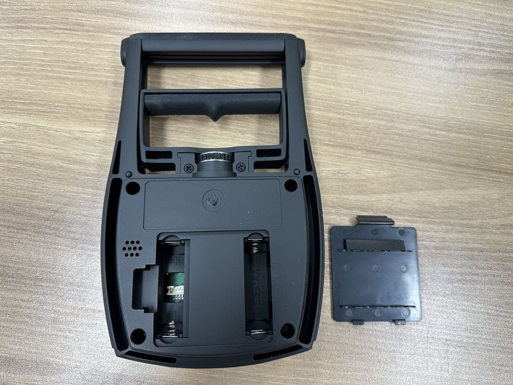
F6OIBHGSM
Sep 27, 2023Hand grip strength dynamometer
Equipment Class
JAB - Part 15 Class B Digital Device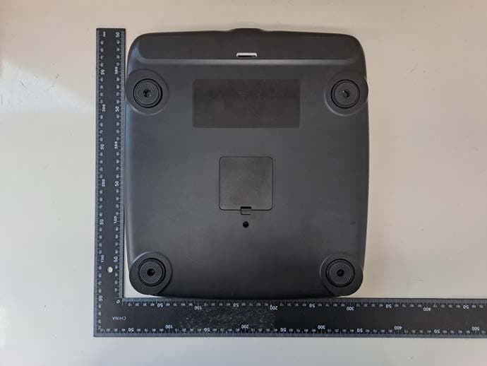
F6OINBODYFIT
Jul 29, 2023Body Composition Analyzer
Equipment Class
DTS - Digital Transmission System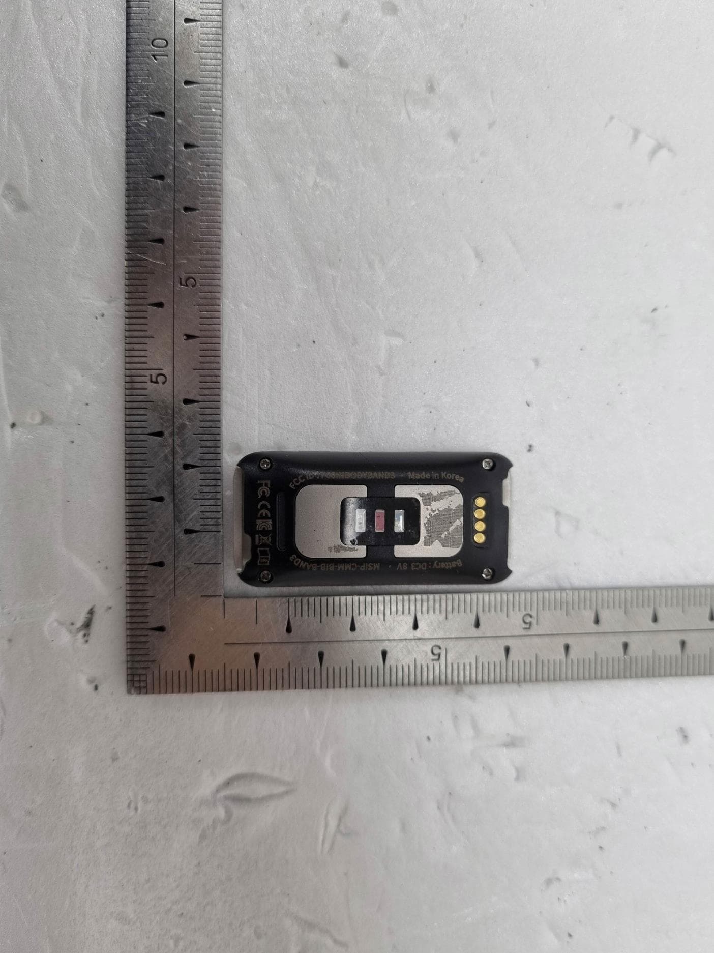
F6OINBODYBAND3
Oct 08, 2021Body Composition Analyzer
Equipment Class
DTS - Digital Transmission System
F6O-INBODY-BP170B
Aug 19, 2020Blood Pressure Monitor
Equipment Class
DTS - Digital Transmission System