FDI-09101457-0Wireless LAN Router
BUFFALO INC.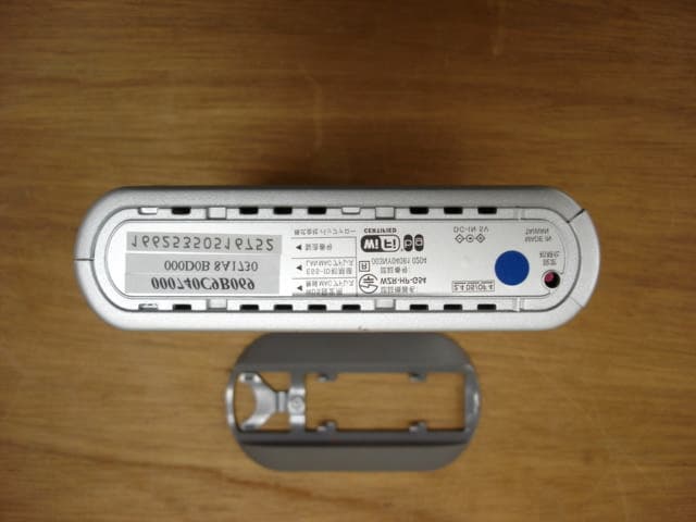
Click to zoom
Application Details
- Equipment Class
- DTS - Digital Transmission System
- Date of Grant
- Jun 21, 2005
- Application Purpose
- Original Equipment
- Date of Application
- Jun 21, 2005
- Equipment Note
- Wireless LAN Router
- Frequency Range
- 2412.00000000 - 2462.00000000
- Company
- BUFFALO INC.
- Country
- Japan
Documents & Files
Document Text
Text extracted from the exhibit documents filed with the FCC. Open a document above to read the original.
Users Manual
User Manual High Power Wireless Broadband Router WZR-HP-G54 www.buffalotech.com 2 Table of Contents Introduction . . . . . . . . . . . . . . . . . . . . . . . . . . . 05 Installation / Setup . . . . . . . . . . . . . . . . . . . . . . 11 Antenna Installation. . . . . . . . . . . . . . . . . . . . . . 13 Standard Settings . . . . . . . . . . . . . . . . . . . . . . . 14 AOSS Setup . . . . . . . . . . . . . . . . . . . . . . . . . . . 23 Advanced Setup . . . . . . . . . . . . . . . . . . . . . . . . 26 LAN Settings . . . . . . . . . . . . . . . . . . . . . . . . 26 Wireless Settings . . . . . . . . . . . . . . . . . . 26 Wireless LAN Security . . . . . . . . . . . . . . 28 LAN Port . . . . . . . . . . . . . . . . . . . . . . . . 32 DHCP Server . . . . . . . . . . . . . . . . . . . . . 33 Wireless MAC Filtering . . . . . . . . . . . . . 36 Wireless Bridge (WDS) . . . . . . . . . . . . . 38 WAN Settings . . . . . . . . . . . . . . . . . . . . . . . 40 WAN Network . . . . . . . . . . . . . . . . . . . . . 43 3 Table of Contents Network Settings. . . . . . . . . . . . . . . . . . . . . 45 Routing Setup . . . . . . . . . . . . . . . . . . . . 45 Address Translation . . . . . . . . . . . . . . . . 47 Packet Filter . . . . . . . . . . . . . . . . . . . . . . 50 Intrusion Detector . . . . . . . . . . . . . . . . . 55 UPnP . . . . . . . . . . . . . . . . . . . . . . . . . . . 57 Management . . . . . . . . . . . . . . . . . . . . . . . . 58 System Information . . . . . . . . . . . . . . . . 58 Change Password . . . . . . . . . . . . . . . . . 59 Time Setup . . . . . . . . . . . . . . . . . . . . . . 60 Traffic Information . . . . . . . . . . . . . . . . . 61 Client Monitor . . . . . . . . . . . . . . . . . . . . 62 Ping Tool . . . . . . . . . . . . . . . . . . . . . . . . 63 Log Information . . . . . . . . . . . . . . . . . . . 64 Syslog Transfer . . . . . . . . . . . . . . . . . . . 65 Save/Restore Settings . . . . . . . . . . . . . . 66 Reboot/Reload Settings . . . . . . . . . . . . . 67 Firmware Updates . . . . . . . . . . . . . . . . . 68 AOSS . . . . . . . . . . . . . . . . . . . . . . . . . . . 69 4 Table of Contents Specifications . . . . . . . . . . . . . . . . . . . . . . . . . 71 Troubleshooting . . . . . . . . . . . . . . . . . . . . . . . . 76 Glossary . . . . . . . . . . . . . . . . . . . . . . . . . . . .84 Disclaimer . . . . . . . . . . . . . . . . . . . . . . . . . . . .90 Certifications . . . . . . . . . . . . . . . . . . . . . . . . . . 91 FCC Information . . . . . . . . . . . . . . . . . . . . . . . . 92 Warranty Information. . . . . . . . . . . . . . . . . . . . . 95 Contact Information . . . . . . . . . . . . . . . . . . . . . 9 6 5 AirStation High Power Wireless Broadband Router (WZR-HP-G54) This manual introduces you to the AirStation Broadband Router, and will help you connect to your network quickly. The WZR-HP-G54 router is a wireless 4-port router network device that complies with the 2.4GHz IEEE 802.11g standard specification for wireless LANs. It also supports 125* High-Speed Mode technology. The WZR-HP-G54 supports enhanced built-in NAT/SPI firewall functions and is used as a multi-functional router/link between wired and wireless LAN computers. Summary of AirStation WZR-HP-G54 features: • Wi-Fi™ (Wireless Fidelity) certified by the Wi-Fi Alliance as an 802.11b/g device. AirStation will communicate with other IEEE 802.11b/g Wi-Fi compliant wireless LAN products. • High-power amplified radio increases range by up tp 70% and performance by up to 50%. • Support s 125* High-Speed Mode. • Support for Wi-Fi Protected Access™ (WPA), 802.1x, TKIP, AES, and WEP. • Supports Frame Bursting for enhanced performance. • DHCP client/server function. • Auto roaming supports seamless roaming over multiple channels. • VPN pass-through for secure communications. • Packet Filtering for eliminating unwanted communications. • SOHO/SMB routing and firewall functions provide a safer private networking environment, Introduction 6 including support for MS NetMeeting and MSN-Messenger. • Additional SPI Firewall Functions: DMZ, intrusion detection, and notification. • Syslog transmits some or all system activities to a central Syslog server. • Extended range with optional add-on antennas or WDS (Wireless Distribution System). • Auto Media Dependent Interface/Crossover (MDI/X) port allows connection by standard and crossover CAT5 cables. • Supports Universal Plug and Play (UPnP). • Includes Buffalo’s AOSS System for easy, secure wireless client configuration. • Enhanced security features: - SPI Firewall and DMZ zone functions to prevent unknown intruders. - Intrusion Detector Firewall (NAT) with pop-up or email alerts when intrusions are detected. - Dynamic packet filtering. - WPA, 802.1x, TKIP, AES, and WEP. - VPN (IPSec, PPTP and L2TP) pass-through - Packet monitoring and filtering by MAC address, IP address and port. - PPPoE support - WDS support • Buffalo’s easy web-based configuration interface. • Broadband router static and dynamic routing methods between WAN and LAN based on updated Introduction 7 routing tables. An economical way to bridge multiple networks. • Optional external antennas for boosting range and signal quality. • Buffalo’s AOSS System for easy, secure wireless client configuration. Home Networking 1 Buffalo AirStation wireless access points enable sharing broadband by simply connecting the AirStation to a DSL or Cable modem to: • Share files and printers. • Access and share the Internet. • Share media files. SOHO/SMB Networking With high speed DSL or Cable connections readily available, many users can work effectively from a home office, connected securely to a corporate network. Buffalo’s solutions are ideal for home networks that require secure, high speed access to the corporate LAN. They include VPN con - nectivity for secure access to corporate resources, which enables remote employees to handle information from clients or coworkers as if they were in the office. Connect …
Text truncated - open the document above for the full version.
Users Manual
51 FTP and WEB. * If IDENT requests are for- warded to a LAN side client by address translation setting (DMZ or TCP port :113 ), this basic rule is ignored. IP Filter Settings - Up to 32 rules may be made to limit the type of packets allowed to pass between the WAN and LAN. Each rule may specify that packets meeting specifi c criteria (source or destination IP Address, Protocol, etc.) from either the WAN or the LAN are ignored, rejected, or accepted. You may choose that packets from the: • WAN side (packets coming from the WAN side will be fi ltered) • LAN side (packets from the LAN side will be fi ltered) are: • Ignored (stops the packet and does not route it) Basic Filter Setting FTP and WEB. * If IDENT requests are for- warded to a LAN side client by address translation setting (DMZ or TCP port :113 ), this basic rule is ignored. Basic Filter Setting Advanced Settings 52 • Rejected (returns the rejected packet to the point of origin) • Accepted (passes the packet through) with each rule. You may also choose: • Destination IP Address - The IP address to be fi ltered. • Source IP Address - The IP address designated for fi ltering. If all IP addresses must be fi ltered, leave this box blank. Warning: If administrator makes a rule that all packets from LAN are Ignored or Rejected, they will no longer have access to the AirStation confi guration screens. This rule prohibits further setup from a wireless or wired computer. The AirStation can be returned to the factory default settings by holding down the INIT button on the back of the unit for fi ve seconds or until the red DIAG light becomes solid. Protocol - You may also choose to fi lter all protocols, ICMP, arbitrary protocol number, or TCP/ UDP protocol number. • All - Selects all IP protocols. IP Filter setting IP Filter setting Advanced Settings 53 • ICMP - Network Diagnostic Protocol (1). • Manual - Enter protocol number (0-65535). • TCP/UDP Destination Port - Select TCP or UDP, then enter port number. Priority - Specify the priority an item. The smaller the number, the higher the priority. MAC Filter - Click Enter MAC fi lter to enter MAC address. Source MAC address -The MAC address of the source of the packets that will be fi ltered may be set. Click Add rule when complete. ■ Note: If confi guring from a wireless computer, add your MAC address to the list of au tho rized wireless LAN PCs. The MAC address must be in two-digit groups separated by colons. Example: 00:40:26:00:11:22 Click Apply when settings are complete. Advanced Settings Add MAC Filter setting 54 Intrusion Detector The Intrusion Detector guards against unauthorized access from the WAN (Internet). This function also records information on unauthorized access attempts Intrusion Detector - Select Disable, Enable, or Enable (Apply Packet filter setting for Intrusion Detector setting). IP Spoofing - Check Block to prevent IP spoofing. Threshold Value - Enter the number (1-999) of suspect packets to be received before the notifica - tion occurs. Advanced Settings 55 Notify by email: Notifi cation email address - Enter des ti na tion email address. Sender email address - Enter the email address that will send the email. This is the name that will appear as the sender when the email is read. This email can be made up (e.g. DETECTOR@AIRSTATION). Intrusion Detector Setup Advanced Settings 56 Sender email server address - Enter the SMTP Server address. Receiving email server authorization - Enter the POP3 Server address, User name and Password. This is only required if your SMTP server requires POP verification before it allows email to be sent. Consult your ISP or mail server support for more information. Send test - Click Send to test notification; this will also save and commit the entries. Pop-up notification - Pop-up window alert of unwanted activity. Client Manager must be installed and running on a client machine to use this feature. Destination IP address - Enter the IP address to be notified. The LAN computer with this IP address - must have Buffalo’s Client Manager software installed and running for the verification to occur. If the machine is off the verification will not be received, and the AirStation will NOT resend information. Intrusion Detector information - displays log activity detected by the Intrusion Detector service. 57 UPnP Select Enable to enable UPnP (Universal Plug and Play). When a computer with UPnP support connects to the AirStation, that computer auto- matically receives confi guration information from the AirStation. Advanced Settings UPnP Setting 58 Management - • System Information - System information of the AirStation is obtained here. • Model name - Displays model and fi rmware version. • AirStation Name - Displays AirStation host name. • DHCP Server function - Displays whether DHCP is On or Off. • Wireless - Displays such wireless LAN settings as wireless MAC address and wireless fi rmware. The wireless MAC address is required for setting up WDS with other access points. This is the best place to determine the wireless MAC address. If 125* Mbps AfterBurner mode is enabled, then the [AfterBurner] color will be red or grey. When it is red, 125* Mbps AfterBurner is running. When it is grey, 125* Mbps AfterBurner is enabled but not running due to a client being connected at 54 Mbps or another access point is running on the same channel. • LAN - Displays the AirStation LAN settings • WAN - Displays the AirStation WAN settings Advanced Settings System Information SystemSystem InformationInformation 59 • Default Gateway - Displays the default gateway settings • WAN side IP address auto acquisition - This acquires an IP address from the WAN (Internet) side DHCP server. Press Release to release current DHCP WAN information. Press Renew to obtain WAN information from the DHCP server. NOTE: If a manual IP is assigned to the WAN port, this feature is not displayed. Admin Name and Password • AirStation name - When using multiple AirStations, select a u…
Text truncated - open the document above for the full version.
External Photos
External Photos of WZR-HP-G54 Front View Side View Back View Top View Bottom View
ID Label/Location Info
Label Location of WZR-HP-G54 The compliance statement provided in Section 15.19 “Labelling requirements” is too large to be printed on this label. Therefore the statement is written in the user manual. The label is affixed to the equipment with robust adhesive. It fastens the label on the equipment firmly until the end of the equipment life span in normal use. Therefore this labelling means complies with the requirement of 2. 295 (d)
Internal Photos
Internal Photos of WZR-HP-G54 Inside of Enclosure Front View of Print Circuit Boards Put Off Enclosure Back View of Print Circuit Board Put Off Enclosure Front View of Antenna Print Board Back View of Antenna Print Board Front View of Main Print Circuit Board Back View of Main Print Circuit Board Front View of RF Module Interface Print Circuit Board Front View of RF Module Interface Print Circuit Board with Shield Off Back View of RF Module Interface Print Circuit Board Front View of RF Module Print Circuit Board Front View of RF Module Print Circuit Board with Shield Off Back View of RF Module Print Circuit Board
RF Exposure Info
Prediction of MPE limit at a given distance Equation from page 18 of OET Bulletin 65, Edition 97-01 Equipment AirStation WZR-HP-G54 Manufacturer Buffalo Inc. Antenna 1AI25P01-CA where:S = power density P = power input to the antenna G = power gain of the antenna in the direction of interest relative to an isotropic radiator R = distance to the center of radiation of the antenna Maximum peak output power at antenna input terminal:25.00(dBm) Maximum peak output power at antenna input terminal:316.227766(mW) Antenna gain(typical):2.6(dBi) Maximum antenna gain:1.819700859(numeric) Prediction distance:20(cm) Prediction frequency:2440(MHz) MPE limit for uncontrolled exposure at prediction frequency:1.00245043(mW/cm^2) Power density at prediction frequency:0.114480(mW/cm^2) Maximum allowable antenna gain:12.02332762(dBi) Margin of Compliance:9.423327618 2 4R PG S π = Prediction of MPE limit at a given distance Equation from page 18 of OET Bulletin 65, Edition 97-01 Equipment AirStation WZR-HP-G54 Manufacturer Buffalo Inc. Antenna 2WLE-HG-NDR where:S = power density P = power input to the antenna G = power gain of the antenna in the direction of interest relative to an isotropic radiator R = distance to the center of radiation of the antenna Maximum peak output power at antenna input terminal:25.00(dBm) Maximum peak output power at antenna input terminal:316.227766(mW) Antenna gain(typical):4.7(dBi) Maximum antenna gain:2.951209227(numeric) Prediction distance:20(cm) Prediction frequency:2440(MHz) MPE limit for uncontrolled exposure at prediction frequency:1.00245043(mW/cm^2) Power density at prediction frequency:0.185665(mW/cm^2) Maximum allowable antenna gain:12.02332762(dBi) Margin of Compliance:7.323327618 2 4R PG S π = Prediction of MPE limit at a given distance Equation from page 18 of OET Bulletin 65, Edition 97-01 Equipment AirStation WZR-HP-G54 Manufacturer Buffalo Inc. Antenna 3WLE-NDR-WR where:S = power density P = power input to the antenna G = power gain of the antenna in the direction of interest relative to an isotropic radiator R = distance to the center of radiation of the antenna Maximum peak output power at antenna input terminal:25.00(dBm) Maximum peak output power at antenna input terminal:316.227766(mW) Antenna gain(typical):2(dBi) Maximum antenna gain:1.584893192(numeric) Prediction distance:20(cm) Prediction frequency:2440(MHz) MPE limit for uncontrolled exposure at prediction frequency:1.00245043(mW/cm^2) Power density at prediction frequency:0.099708(mW/cm^2) Maximum allowable antenna gain:12.02332762(dBi) Margin of Compliance:10.02332762 2 4R PG S π = Prediction of MPE limit at a given distance Equation from page 18 of OET Bulletin 65, Edition 97-01 Equipment AirStation WZR-HP-G54 Manufacturer Buffalo Inc. Antenna 4WLI-MYG where:S = power density P = power input to the antenna G = power gain of the antenna in the direction of interest relative to an isotropic radiator R = distance to the center of radiation of the antenna Maximum peak output power at antenna input terminal:25.00(dBm) Maximum peak output power at antenna input terminal:316.227766(mW) Antenna gain(typical):3.9(dBi) Maximum antenna gain:2.454708916(numeric) Prediction distance:20(cm) Prediction frequency:2440(MHz) MPE limit for uncontrolled exposure at prediction frequency:1.00245043(mW/cm^2) Power density at prediction frequency:0.154429(mW/cm^2) Maximum allowable antenna gain:12.02332762(dBi) Margin of Compliance:8.123327618 2 4R PG S π = Prediction of MPE limit at a given distance Equation from page 18 of OET Bulletin 65, Edition 97-01 Equipment AirStation WZR-HP-G54 Manufacturer Buffalo Inc. Antenna 5WLE-DA where:S = power density P = power input to the antenna G = power gain of the antenna in the direction of interest relative to an isotropic radiator R = distance to the center of radiation of the antenna Maximum peak output power at antenna input terminal:25.00(dBm) Maximum peak output power at antenna input terminal:316.227766(mW) Antenna gain(typical):4(dBi) Maximum antenna gain:2.511886432(numeric) Prediction distance:20(cm) Prediction frequency:2440(MHz) MPE limit for uncontrolled exposure at prediction frequency:1.00245043(mW/cm^2) Power density at prediction frequency:0.158027(mW/cm^2) Maximum allowable antenna gain:12.02332762(dBi) Margin of Compliance:8.023327618 2 4R PG S π =
Test Report
Page 1 of 51 Test Report No. R047363E Cosmos Corporation COSMOS MEASUREMENT/TECHNICAL REPORT FCC Part 15 Subpart C Issued: June 22, 2005 Name and Address Buffalo Inc. of the Applicant: 15,Shibata Hondori 4,Minami-ku Nagoya, Aichi Japan 457-8520 Test Item: Wireless LAN Router Identification: “AirStation” WZR-HP-G54 Serial No.: 16625350516752 Sample No.: 1 Sample Receipt Date: June 2, 2005 Test Specification: CFR 47 Part.15 Subpart C 15.247 Date of Testing: June 2 nd – 16 th , 2005 Test Result: PASS Report Prepared by: Cosmos Corporation 2-3571 Ohnogi, Watarai-cho, Watarai-gun, Mie, Japan 516-2102 Phone: +81-596-63-0707 Fax: +81-596-63-0777 Cosmos Corporation EMC Lab. No.1 543 Shimesasu, Watarai-cho, Watarai-gun, Mie-ken, 516-2119 Japan Phone: +81-596-64-0888 Fax: +81-596-64-0895 Tested by: June 22, 2005 D. Watanuki, Engineer Date Reviewed by: June 22, 2005 Y. Kawahara, Leader Date Notes: 1. This report should not be reproduced except in full, without the written approval of Cosmos Corporation. 2. All measurement data contained in this report may have uncertainty. A judgement for the limitation should be taken into the count. 3. The report in this report apply only to the sample tested. Page 2 of 51 Test Report No. R047363E Cosmos Corporation COSMOS List of Contents Page 1. Description of Equipment Under Test................................................................................................4 1.1 Product Description......................................................................................................................4 1.2 Antenna Description.....................................................................................................................4 2. General Information.............................................................................................................................5 2.1 Test Methodology..........................................................................................................................5 2.2 Test Facility..................................................................................................................................5 2.3 Traceability...................................................................................................................................5 3. Summary of Test Results.....................................................................................................................5 4. Test Configuration................................................................................................................................6 4.1 15. 207 AC Power Conducted Emission in Shield Room.........................................................6 4.2 15. 247(c) Transmitter Radiated Emissions (Radiated) in 3m Anechoic Chamber...............6 4.3 All Other Test Items (Except Maximum Peak Output Power)...............................................7 4.4 Maximum Peak Output Power..................................................................................................7 4.5 Test Mode....................................................................................................................................7 5. Measurement Result.............................................................................................................................8 5.1 15. 207 AC Power Conducted Emission....................................................................................8 5.1.1 Setting Remarks..................................................................................................................8 5.1.2 Minimum Standard.............................................................................................................8 5.1.3 Result...................................................................................................................................8 5.1.4 Measured Data....................................................................................................................9 5.2 15. 247(a)(2) Spectrum Bandwidth of Direct Sequence Spread Spectrum System.............11 5.2.1 Setting Remarks................................................................................................................11 5.2.2 Minimum Standard...........................................................................................................11 5.2.3 Result.................................................................................................................................11 5.2.4 Measured Data..................................................................................................................11 5.3 15. 247(b) Maximum Peak Output Power..............................................................................15 5.3.1 Setting Remarks................................................................................................................15 5.3.2 Minimum Standard...........................................................................................................15 5.3.3 Result.................................................................................................................................15 5.3.4 Measured Data..................................................................................................................15 5.4 15. 247(c) Transmitter Radiated Emissions (Conducted).....................................................16 5.4.1 Setting Remarks................................................................................................................16 5.4.2 Minimum Standard...........................................................................................................16 5.4.3 Result.................................................................................................................................16 5.4.4 Measured Data (No significant emission was found).....................................................17 5.5 15. 247(c) Transmitter Radiated E…
Text truncated - open the document above for the full version.
Test Setup Photos
Page 45 of 51 Test Report No. R047363E Cosmos Corporation COSMOS 6. Photos 6.1 Setup Photo (Conducted Emission) Front View Side View Page 46 of 51 Test Report No. R047363E Cosmos Corporation COSMOS 6.2 Setup Photo (Radiated Emission) Front View (Antenna 1) Rear View (Antenna 1) Page 47 of 51 Test Report No. R047363E Cosmos Corporation COSMOS Front View (Antenna 2) Rear View (Antenna 2) Page 48 of 51 Test Report No. R047363E Cosmos Corporation COSMOS Front View (Antenna 4) Rear View (Antenna 4) Page 49 of 51 Test Report No. R047363E Cosmos Corporation COSMOS Front View (Antenna 5) Rear View (Antenna 5)
Contact Information
Applicant
Mr. Masaya Ishimaru(General Manager)
Technical Contact
Cosmos CorporationDavid Watanuki
[email protected]+81-596-63-0707
2-3571 Ohnogi, Watarai-cho, · Mie · Japan
Test Firm
Cosmos CorporationEiji Asano
Technical Specifications
| # | Rule Parts | Frequency Range | Power Output |
|---|---|---|---|
| 1 | 15C | 2.41 GHz - 2.46 GHz | 316.00 mW |
Other Applications from BUFFALO INC.

FDI000000028
Mar 15, 2015AirStation
Equipment Class
DTS - Digital Transmission System
FDI000000027
Jan 22, 2015MiniStation
Equipment Class
DXX - Part 15 Low Power Communication Device Transmitter
FDI000000022
Oct 12, 2014AirStation
Equipment Class
DTS - Digital Transmission System
FDI000000026
Oct 01, 2014AirStation
Equipment Class
DTS - Digital Transmission System
FDI000000024
Apr 21, 2014AirStation
Equipment Class
DTS - Digital Transmission System