FDI000000019LPV4-U2-300S
BUFFALO INC.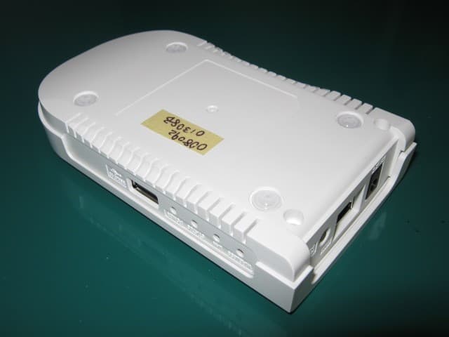
Click to zoom
Application Details
- Equipment Class
- DTS - Digital Transmission System
- Date of Grant
- Sep 30, 2013
- Application Purpose
- Original Equipment
- Date of Application
- Sep 30, 2013
- Equipment Note
- LPV4-U2-300S
- Frequency Range
- 2422.00000000 - 2452.00000000
- Company
- BUFFALO INC.
- Country
- Japan
Documents & Files
Document Text
Text extracted from the exhibit documents filed with the FCC. Open a document above to read the original.
Users Manual
Print Server LPV4-U2-300S User Manual www.buffalotech.com 35020190-01 2 Contents Chapter 1 - Configuration .................................................5 Introduction .........................................................................................5 Accessing Settings ...............................................................................6 Access by IP Address .......................................................................................6 Access from Network-USB Navigator ............................................................7 Status ....................................................................................................9 Device Status ...................................................................................................9 System Status ................................................................................................10 Wireless Status ..............................................................................................10 Network ..............................................................................................11 General Settings ...........................................................................................11 TCP/IP .............................................................................................................12 Wireless LAN Settings (Easy Setup) .............................................................13 Wireless LAN Settings (Advanced Settings) ................................................14 Wireless LAN Settings (WPS Settings) .........................................................15 Security ...............................................................................................16 Password Options .........................................................................................16 Maintenance .......................................................................................17 Restart ...........................................................................................................17 Initialize .........................................................................................................17 Firmware Update ..........................................................................................18 Default Configuration Settings .........................................................19 3 Chapter 2 - Network-USB Navigator ..............................20 Introduction .......................................................................................20 Install Network-USB Navigator .........................................................20 For Windows Users ........................................................................................20 For Mac Users ................................................................................................24 Confirm Settings ...........................................................................................27 Connect and Disconnect ....................................................................29 How to Connect to Printer ............................................................................29 How to Disconnect Printer ...........................................................................30 Send Disconnect Request ..................................................................31 Main Window ......................................................................................33 Buttons ..........................................................................................................33 Status .............................................................................................................34 Options ...............................................................................................34 How to Open Options ...................................................................................34 Description ....................................................................................................35 Notes ...................................................................................................37 Chapter 3 - Settings .........................................................38 Print Data from Your Mobile ..............................................................38 Check Ink Level ...................................................................................38 Use Scanning Function ......................................................................39 Change Print Server’s IP Address ......................................................39 Switch from Wired to Wireless Connection ......................................40 Select Wireless Access Point from List .........................................................40 4 Connect by WPS Pushbutton Method .........................................................42 Connect by WPS PIN .....................................................................................43 Switch from Wireless to Wired Connection ......................................44 Initializing the Print Server ...............................................................45 Press WPS Button ..........................................................................................45 Configure in Settings ....................................................................................45 Chapter 4 - Troubleshooting ...........................................46 Cannot Print........................................................................................46 Cannot Access Print Server from PC .................................................47 Print Server Is Not Displayed on LPV4 Port Setup Wizard ..............48 Print Server Is Not Displayed on Network-USB Navigator ..............50 Cannot Find Access Point from Settings ..........................................51 Cannot Connect Wirelessly Using WPS .............................................52 Forgot IP Address ....…
Text truncated - open the document above for the full version.
Cover Letter(s)
Statement We, Cosmos Corporation have evaluated Print Server with model number: LPV4-U2-300S as applying to FCC DOC, because this printer server can be connected to computer. The test report number is I117672-1. Your assistance on this matter is highly appreciated. Yours sincerely, Signature: Dated this September 27, 2013 By: Hiroki Onishi Signature Printed Title: EMC Manager Testing Lab. Cosmos Corporation
External Photos
Picture 1 Picture 2 Page 1 of 3 Picture 3 Picture 4 Page 2 of 3 Picture 5 Page 3 of 3
ID Label/Location Info
PANTONE BLACK Base Color Model:LPV4-U2-300S MADE IN JAPANInput: 5V 2A This device complies with part 15 of the FCC Rules. Operation is subject to the following two conditions (1) This device may not cause harmful interference, and (2) This device must accept any interference received, including interference that may cause undesired operation. IC: 6102A-054CAN ICES-3 (B)/NMB-3 (B) IEEE802.11b/g/n FCC ID: FDI000000019 E112597 Electrical Safety : 2.3W : 460mA S/N:XXXXXXXXXXXXXX MAC:XXXXXXXXXXXXXX
ID Label/Location Info
Drawing No.JW201220XA Date June 27, 2013 (15/16) CONFIDENTIAL © silex technology, Inc. .
Internal Photos
Picture 1 Picture 2 Page 1 of 3 Picture 3 Picture 4 Page 2 of 3 Picture 5 Page 3 of 3
RF Exposure Info
Prediction of MPE limit at a given distance Equation from page 18 of OET Bulletin 65, Edition 97-01 Equipment LPV4-U2-300S Manufacturer Buffalo Inc. where:S = power density P = power input to the antenna G = power gain of the antenna in the direction of interest relative to an isotropic radiator R = distance to the center of radiation of the antenna Total Power* density at prediction frequency:15.607431 (mW/cm^2) Margin of Compliance:-11.93331412 Note: "Total Power" means added Values, both of Antenna A and Antenna B. Detail is below: (Antenna : A) Maximum peak output power at antenna input terminal:21.44 (dBm) Maximum peak output power at antenna input terminal:139.3156803 (mW) Antenna gain(typical):2 (dBi) Maximum antenna gain:1.584893192 (numeric) Prediction distance:20 (cm) Prediction frequency:2437 (MHz) MPE limit for uncontrolled exposure at prediction frequency:1 (mW/cm^2) Power density at prediction frequency:0.043927 (mW/cm^2) Maximum allowable antenna gain:15.57269855 (dBi) (Antenna : B) Maximum peak output power at antenna input terminal:20.42 (dBm) Maximum peak output power at antenna input terminal:110.153931 (mW) Antenna gain(typical):2 (dBi) Maximum antenna gain:1.584893192 (numeric) Prediction distance:20 (cm) Prediction frequency:2437 (MHz) MPE limit for uncontrolled exposure at prediction frequency:1 (mW/cm^2) Power density at prediction frequency:0.034732 (mW/cm^2) Maximum allowable antenna gain:16.59269855 (dBi) 2 4R PG S
Test Report
Page 2 of 65 Test Report No. R118102-1 Rev.04 ERF130301 Cosmos Corporation QAF1466 Issued: 13/03/01 Revised: --/--/-- List of Contents Page 1. Description of Equipment under Test....................................................................................... 4 1.1 Product Description .................................................................................................................. 4 1.2 Antenna Description ................................................................................................................. 5 1.3 Accompanied Peripherals Description ...................................................................................... 5 2. General Information.................................................................................................................. 6 2.1 Test Methodology ...................................................................................................................... 6 2.2 Test Facility .............................................................................................................................. 6 2.3 Traceability ............................................................................................................................... 6 3. Test Condition (Manufacturer’s Specification) ......................................................................... 6 3.1 Mode of Operation..................................................................................................................... 6 3.2 Test Configuration .................................................................................................................... 7 3.3 EUT Angle............................................................................................................................... 11 3.4 Photograph of EUT ................................................................................................................. 11 3.5 Test Mode ................................................................................................................................ 12 4. Summary of Test Results ........................................................................................................ 13 5. Measurement Result ............................................................................................................... 14 5.1 15. 207 AC Power Line Conducted Emission.......................................................................... 14 5.1.1 Setting Remarks.................................................................................................................14 5.1.2 Minimum Standard............................................................................................................14 5.1.3 Result ..................................................................................................................................14 5.1.4 Measured Data ...................................................................................................................15 5.2 15. 247(b) Maximum Peak Conducted Output Power ............................................................ 27 5.2.1 Setting Remarks.................................................................................................................27 5.2.2 Minimum Standard............................................................................................................27 5.2.3 Result ..................................................................................................................................27 5.2.4 Measured Data ...................................................................................................................28 5.3 15. 247(a) 6 dB Bandwidth ..................................................................................................... 32 5.3.1 Setting Remarks.................................................................................................................32 5.3.2 Minimum Standard............................................................................................................32 5.3.3 Result ..................................................................................................................................32 5.3.4 Measured Data ...................................................................................................................33 5.4 15. 247(d) Transmitter Spurious Emission (Conducted) ........................................................ 35 5.4.1 Setting Remarks.................................................................................................................35 5.4.2 Minimum Standard............................................................................................................35 5.4.3 Result ..................................................................................................................................35 5.4.4 Measured Data ...................................................................................................................36 5.5 15. 209 Transmitter Spurious Emission (Radiated) ............................................................... 38 5.5.1 Setting Remarks.................................................................................................................38 Page 3 of 65 Test Report No. R118102-1 Rev.04 ERF130301 Cosmos Corporation QAF1466 Issued: 13/03/01 Revised: --/--/-- 5.5.2 Minimum Standard............................................................................................................39 5.5.3 Result ..................................................................................................................................39 5.5.4 Measured Data ...................................................................................................................39 5.6 15. 247(d) Band Edge Measurement....................................................................................... 52 5.6.1 Setting …
Text truncated - open the document above for the full version.
Test Setup Photos
Test Setup Photos External Photo of EUT AC Power Line Conducted Emission Radiated Emission Below 1 GHz Radiated Emission (Continued) Above 1 GHz Antenna Port Conducted Emission
Contact Information
Applicant
Mr. Masaya Ishimaru(General Manager)
Test Firm
Cosmos CorporationEiji Asano
Technical Specifications
| # | Rule Parts | Frequency Range | Power Output |
|---|---|---|---|
| 2 | 15C | 2.42 GHz - 2.45 GHz | 184.50 mW |
Other Applications from BUFFALO INC.

FDI000000028
Mar 15, 2015AirStation
Equipment Class
DTS - Digital Transmission System
FDI000000027
Jan 22, 2015MiniStation
Equipment Class
DXX - Part 15 Low Power Communication Device Transmitter
FDI000000022
Oct 12, 2014AirStation
Equipment Class
DTS - Digital Transmission System
FDI000000026
Oct 01, 2014AirStation
Equipment Class
DTS - Digital Transmission System
FDI000000024
Apr 21, 2014AirStation
Equipment Class
DTS - Digital Transmission System