FI7MCIV5656K Data/FAX Internal Modem
Archtek Telecom Corporation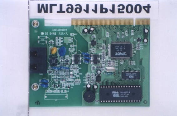
Click to zoom
Application Details
- Equipment Class
- JBP - Part 15 Class B Computing Device Peripheral
- Date of Grant
- Jan 13, 2000
- Application Purpose
- Original Equipment
- Date of Application
- Dec 12, 1999
- Equipment Note
- 56K Data/FAX Internal Modem
- Company
- Archtek Telecom Corporation
- Country
- Taiwan
Documents & Files
Document Text
Text extracted from the exhibit documents filed with the FCC. Open a document above to read the original.
Users Manual
1 5634 PCV User’s Manual 2 Table Contents Table Contents..........................................................................................2 Chapter 1 Installation..............................................................................3 1. 1 Checking your components......................................................3 1. 2 What else you need..................................................................3 1. 3 Removing the computer cover..................................................3 1. 4 Inserting the modem.................................................................4 1. 5 Connecting to the telephone line..............................................5 1. 6 Connecting to your telephone...................................................5 1. 7 Verifying your connection.........................................................6 1. 8 Windows 95/98 Modem Driver Installation ( PnP)....................7 1. 9 Windows NT4.0 Modem Driver Installation ..............................8 1.10 Linux Red Hat 6.0 Modem Driver Installation .........................8 1.11 MS-DOS Modem Driver Installation ........................................9 Chapter 2 AT commands set................................................................11 2. 1 Data Mode Command............................................................11 2. 2 Result Code............................................................................23 2. 3 S Registers Definitions...........................................................25 2. 4 Class 1 Fax Commands.........................................................32 2. 5 Voice Commands...................................................................35 2. 6 AT% TTn Commands.............................................................37 3 Chapter 1 Installation Chapter 1 provides detailed instructions for installing your modem. 1.1 Checking your components Unpack your components and make sure you have the following items: l The modem. l A modular telephone cable to connect your modem to the telephone line. l This user's manual. l Communication software and manual. When you open your package, make sure all of the above items are included and not damaged. If you see that any components are damaged, please notify your dealer immediately. 1.2 Installing the modem The following instructions explain how to install the modem in a IBM compatible type personal computer. If you will be installing the modem into a different computer, refer to the manual that accompanied your computer or contact your computer dealer for instructions on installing the modem in your personal computer. 1.3 Removing the computer cover Turn off the personal computer's power. No power must be applied to your computer when you install the internal modem and computer could be damaged. Make sure you can freely access the back of the personal computer. Unscrew the necessary screws to loosen the computer cover. Then set the 4 screws in a safe place and remove the computer cover. 1.4 Inserting the modem The internal modem can fit into any available PCI slot in your personal computer. To insert the internal modem in your personal computer: 1. Position yourself so that you can easily access the computer's expansion slots. 2. Select any available half-card slot into which you can install the internal modem. 3. Remove any slot cover that may be over the slot. Then remove the slot cover and keep both in a safe place (you will need the screw to secure the internal modem and you may need the slot cover if you decide to remove the internal modem in the future). 4. Hold the internal modem above the slot you selected, making sure the modem's edge connectors are pointing down toward the base of the personal computer (see Figure1-1). 5. Carefully slide the modem into the PCI slot, applying even pressure to both ends of the modem. Stop inserting the modem when its gold-plated edge connectors are aligned with and completely fit into the base of the computer. 6. If you removed a screw from the slot cover, use that screw to secure the modem in the PCI slot. You may want to test the modem's telephone connection (described in the next section) before securing your modem. 7. Use the cover-mounting screws to secure the computer cover. Figure 1-1. Inserting the modem 5 1.5 Connecting to the telephone line Use the following procedure to connect your modem to the telephone line: 1. Make sure you have an RJ-11 telephone jack. If you need a modular jack, either obtain a telephone adapter from a telephone or electronics store and follow the installation instructions provided with the adapter, or have your local telephone company replace your existing telephone jack with a modular-type jack and your existing telephone cord with a modular cord. 2. Unplug your telephone's cable from the wall jack. 3. Take one end of the modular telephone cable supplied with the modem and plug it into the LINE modular telephone jack on the back of the modem (see Figure 1-2). 4. Plug the other end of the telephone cord into the telephone jack on the wall, as you would any modular telephone. 1.6 Connecting to your telephone Your modem is so convenient, it provides a second modular telephone jack that lets you connect your telephone to the same telephone line the modem is using. This lets you manually dial data calls or make voice calls when you are not using your modem. Use the following procedure to connect your telephone to your modem: Connect the telephone's modular cord into the PHONE jack on the back of your modem (see Figure 1-3). Lift your telephone's handset and listen for a dial tone. 6 LINE PHONE 5634PCV Figure 1-2. Back of the modem 1.7 Verifying your connection Before you proceed to next step, make sure your connection matches the one shown in Figure 1-3. MODEM CARD PHONE JACK JACK LINE LINE PHONE 5634PCV Figure 1-3. Completed modem installation If you connected the modem to a computer, place the computer into terminal mode and complete the co…
Text truncated - open the document above for the full version.
Block Diagram
Telephone Line Silicon DAA Si3035 set RAM 32K*8 MCU TP560i OPA LM386 PC CPU Drawed by: Checked by: Approved by: Date: 5634PCV Block Diagarm FLASH 256K*8 NVRAM PCI BUS Buzzer
Cover Letter(s)
MESSERS: Max Light Technology Co.,LtdDATE: 10/28/1999 POWER OF ATTORNEY SUBJECT: FCC APPLICATION We, the undersigned, hereby authorize Max Light Technology Co.,Ltd. To act on our behalf in all matters relating to application for equipment authorization of our model: 5634PCV including the signing of all documents relating to these matters. Any and all acts carried out by Max Light Technology Co.,Ltd. On our behalf shall have the same effect as acts of our own. Applicant: Archtek Telecom Corporation. By: Mahan Chu Signature Printed Title: Vice President
External Photos
MAX LIGHT Report Number: MLT9911P15004 FCC ID: FI7MCIV56 Technology Lab MAX LIGHT Report Number: MLT9911P15004 FCC ID: FI7MCIV56 Technology Lab MAX LIGHT Report Number: MLT9911P15004 FCC ID: FI7MCIV56 Technology Lab
ID Label/Location Info
MAX LIGHT Report Number: MLT9911P15004 FCC ID: FI7MCIV56 Technology Lab Label Format: Label Position: This device complies with Part15 of the FCC Rules. Operation is subject to the following two conditions: (1) This device may not cause harmful interference,and (2) This device must accept any interference received ,including. Interference that may cause undesired operation. Model: 5634PCV FCC ID: FI7MCIV56 MADE IN TAIWAN Equipment Lable 3CMX4CM Rear View
Schematics
A A B B C C D D E E 44 33 22 11 C33=10uF,OP_Gain=200 C33=NI ,OP_Gain=20 B DAA.SCHA 5634PCV_A ARCHTEK TELECOM CORPORATION 12Wednesday, September 08, 1999 126B2060000A Title SizeDocument NumberRev Date:Sheetof POR\ SP_SCLK RI\ SP0_FR OH\ SP0_RD SP0_TD POR\ AFE_CLK VDD VDD VDD R340R U2 Si3012 1 2 3 4 5 6 7 89 10 11 12 13 14 15 16 TSTA/QE2 TSTB/DCT IGND C1B RNG1 RNG2 QB QEVREG NC/VREG2 NC/REF DCT/REXT2 REXT RX NC/FILT TX/FILT2 Q4 NPN 1 2 3 + C10NI FB1 RV1 FB2 C26 39nF C21 NI C17 NI C19 NI C250.015uF C12NI C2 NI R1451R R22 15R R312K R3220K R21 NI R5NI R6NI R11NI R12NI R20 36k C22 NI C24 NI C4 1nF/AC 250V C13 1nF C18150pF C9 NI CX90.015uF C11 1nF C3 NI C15 NI C16 1nF/AC 250V CNT1A RJ11 1 4 3 2 CNT1B RJ11 5 8 7 6 Z2 NI 2 1 Z3 18V 2 1 -+ D1 BRIDGE 4 1 3 2 CX14NI +C23 NI R25 NI R26 NI R27 NI R28 NI R8 301R + C141uFZ1 NI 2 1 R13 NI R4 2K R1 20K R30NI C10.015uF R3NI R20R R15220 C8 0.1uF C7 0.1uF U1 SI3021 1 2 3 4 5 6 7 89 10 11 12 13 14 15 16 MCLK FSYNC SCLK VD SDO SDI FC RESET AOUT M1 C1A GND VA M0 RGDT OFHK R16220 + C6 10uF R18 220 R7 NI + C29 10 uF LS1 BUZZER C30 NI C31 0.1uF R36 NI R37 NI C27 0.1 uF R35 0R + - U3 LM386M-1 3 2 5 61 48 7 +C33 10uF C28 0.1 uF C32 0.1 uF R10 10R R24 NI R17 36 k Q3 PNP 1 23 Q2 NPN 1 23 Q1 NI 1 3 2 R190 R23 2700pF C20 0.047uF R9301R C5 0.1uF 1 1 2 2 3 3 4 4 5 5 6 6 7 7 8 8 AA BB CC DD 126B2060000A MCU.SCHA 5634PCV_A ARCHTEK TELECOM CORPORATION B 22Wednesday, September 08, 1999 Title SizeDocument NumberRev Date:Sheetof PSEN\ FLHWR\ RD\ WR\ C/BE1# IRDY# IDSEL INTA# FRAME# RST# CLK C/BE0# PAR TRDY# DEVSEL# C/BE2# STOP# HA14 HA2 AD3 HA12 HD7 HD1 AD28 HA15 HA1 WR\ HA16 HD0 HD1 HD2 PAR STOP# TRDY# IRDY# FRAME# AD18 INTA# HD4 HD0HA0 HA1 HA15 AD26 AD15 AD21 HA3 HA2 HA0 HD3 HD4 OSCI AD8 C/BE1# C/BE2# AD17 HD3 AD26 AD9 HD2 HA8 HA14 HD7 AD9 HA12 AD25 AD27 AD2 HA3HA4 HA13 C/BE3# RST# AD14 AD8 AD1 C/BE0# AD17 AD12 AD4 AD18 HA9 CLK HA7 HA11 OSCOAD23 AD29 HA6 HA17 HA14 HA0 AD19 HA9 HD6 HA16 AD30 HA10 HA10HA8 HA11 AD2 HA5 HD1 AD31 HD5 AD20 AD23 HD5 HD6 AD5 AD22 AD25 HD[0..7] HA12 HD4 AD16 AD15 HA4 PSEN \ RD\ AD30AD27 AD13 AD14 AD16 AD20 IDSEL AD24 AD6 HA11 HA3 AD10 AD5 HA13 AD1 HD2 HA10 AD6 AD7 AD21 HA8 HD7 HA2 HA17 AD29 DEVSEL# OH\ HA6 AD11 HA5 AD13 HA7 HA4 AD22 HA15 FLHWR\HA9 HA[0..17] HD0 HD6 HA7 HD5 AD24 HA1 AD4 HA6 AD10 RI\ AD7 HA13 AD0 HA5 AD31AD28 AD11 AD12 HD3 AD0 AD3 AD19 C/BE3# AD[31..0] OH\ RI\ SP0_FR SP0_RD FLHWR\ PSEN\ WR\ SP_SCLK POR\ SP0_TD AFE_CLK RD\ VDD VDD 3.3V 3.3V VDD VDD VDD 3.3V 3.3V 3.3V VDD VDD VDD VDD3.3V 3.3V VDD VDD3.3V VDD VDD VDD VDD 3.3V 3.3V VDD VDD VDDVDD Y1 36.864MHZ L1 5.6uH 12 C38 18pF C43 0.1uF L2 BEAD 12 R41 1M R44 220 R40 22 R42 22 R38 3.3k R43 22 U6 27C020 12 11 10 9 8 7 6 5 27 26 23 25 4 28 29 3 2 22 24 13 14 15 17 18 19 20 21 32 31 30 1 16 A0 A1 A2 A3 A4 A5 A6 A7 A8 A9 A10 A11 A12 A13 A14 A15 A16 CE OE O0 O1 O2 O3 O4 O5 O6 O7 VCC PGM A17 VPP GND U4 93C46 1 2 3 45 6 7 8 CS SK DI DOGND NC NC VCC R39 NI C54 10uF C44 0.1uF C34 0.1uF J1 PCICONN 1 2 3 4 5 6 7 8 9 10 11 12 13 14 15 16 17 18 19 20 21 22 23 24 25 26 27 28 29 30 31 32 33 34 35 36 37 38 39 40 41 42 63 64 65 66 67 68 69 70 71 72 73 74 75 76 77 78 79 80 81 82 83 84 85 86 87 88 89 90 91 92 93 94 95 96 97 98 99 100 101 102 103 104 105 106 107 108 109 110 111 112 113 114 115 116 117 118 119 120 121 122 123 124 43 44 45 46 47 48 49 52 53 54 55 56 57 58 59 60 61 62 50 51 -12V TCK GROUND TD0 5V 5V INTB* INTD* PRSNT1* NC PRSNT2* GROUND GROUND NC GROUND CLK GROUND REQ* 5V AD31 AD29 GROUND AD27 AD25 3.3V C/BE3* AD23 GROUND AD21 AD19 3.3V AD17 C/BE2* GROUND IRDY* 3.3V DEVSEL* GROUND LOCK* PERR* 3.3V SERR* TRST* 12V TMS TDI 5V INTA* INTC* 5V NC 5V NC GROUND GROUND NC RST* 5V GNT* GROUND NC AD30 3.3V AD28 AD26 GROUND AD24 IDSEL 3.3V AD22 AD20 GROUND AD18 AD16 3.3V FRAME* GROUND TRDY* GROUND STOP* 3.3V SDONE SBO* GROUND PAR AD15 3.3V AD13 AD11 GROUND AD9 NC NC C/BE0* 3.3V AD6 AD4 GROUND AD2 AD0 5V REQ64* 5V 5V 3.3V C/BE1 AD14 GROUND AD12 AD10 GROUND AD8 AD7 3.3V AD5 AD3 GROUND AD1 5V ACK64* 5V 5V NC NC C40 18pF C41 18pF C55 10uF Q5 AIC1722-33CX 3 2 1 IN GND OUT C39 10uF C53 0.1uF C36 0.1uF C47 0.1uF U7 61256 10 9 8 7 6 5 4 3 25 24 21 23 2 20 27 22 11 12 13 15 16 17 18 19 26 1 28 14 A0 A1 A2 A3 A4 A5 A6 A7 A8 A9 A10 A11 A12 CS1 WE OE D0 D1 D2 D3 D4 D5 D6 D7 A13 A14 VCC GND C48 0.1uF C52 0.1uF C35 0.1uF C45 0.1uF C51 0.1uF C49 0.1uF C37 10uF U5 TP560I 1 2 3 4 5 6 7 8 9 10 11 12 13 14 15 16 17 18 19 20 21 22 23 24 25 26 27 28 29 30 31 32 33 34 35 36 37 38 128127126125124123122121120119118117116115114113112111110109108107106105104103 102 101 100 99 98 97 96 95 94 93 92 91 90 89 88 87 86 85 84 83 82 81 80 79 78 77 76 75 74 73 72 71 70 69 68 67 66 65 6463626160595857565554535251504948474645444342414039 AD25 AD24 C/BE3 IDSEL AD23 AD22 AD21 AD20 AD19 GND AD18 AD17 AD16 VDD3.3V C/BE2 FRAME IRDY TRDY GND DEVSEL STOP PAR C/BE1 AD15 AD14 VDD5V GND AD13 AD12 AD11 AD10 GND AD9 AD8 C/BE0 AD7 AD6 AD5 AD26AD27 GND AD28AD29AD30AD31 GND VDD5V GND PCICLK RESET INTA VDD3.3V TEST0TEST1 USEOSC EECS EESK EEDATA LCS GPIO7GPIO6GPIO5GPIO4GPIO3 GPIO2 VDD5V GND AVDD3.3V OSCO OSCI AGND GPIO1 GPIO0 VDD3.3V HD7 HD6 HD5 HD4 HD3 HD2 HD1 HD0 VDD5V CODECLK FS0 GND SCLK DR0 DT0 VDD3.3V CODRST GND HA17 HA16 HA15 HA14 HA13 HA12 HA11 HA10 GND VDD3.3V HA9HA8HA7HA6HA5HA4GNDHA3HA2HA1HA0WRRDPSENFLHWRVDD5VGNDVDD3.3VOHRIAD0AD1AD2GNDAD3AD4 R48200 R47200 R46200 R45200
Test Report
MAX LIGHT Report Number: MLT9911P15004 FCC ID: FI7MCIV56 Technology Lab MAX LIGHT Report Number: MLT9911P15004 FCC ID: FI7MCIV56 Technology Lab MAX LIGHT Report Number: MLT9911P15004 FCC ID: FI7MCIV56 Technology Lab
Test Report
Product : 56K Data/Fax Internal Modem Manufacture : Archtek Telecom Corporation. FCC ID : FI7MCIV56 Model : 5634PCV Report No. : MLT9901P15001 Test Date : December 10.1999 Test By Max Light Technology Co.,Ltd. Room 5, 8F, No.125, Section 3 Roosevelt Road, Taipei, Taiwan., R.O.C. Tel: 886-2-2363-2447 Fax: 886-2-2363-2597 T T h h e e t t e e s s t t r r e e p p o o r r t t c c o o n n s s i i s s t t s s o o f f 2 2 1 1 p p a a g g e e s s i i n n t t o o t t a a l l . . I I t t m m a a y y b b e e d d u u p p l l i i c c a a t t e e d d c c o o m m p p l l e e t t e e l l y y f f o o r r l l e e g g a a l l u u s s e e w w i i t t h h t t h h e e a a l l l l o o w w a a n n c c e e o o f f t t h h e e a a p p p p l l i i c c a a n n t t . . I I t t s s h h a a l l l l n n o o t t b b e e r r e e p p r r o o d d u u c c e e d d e e x x c c e e p p t t i i n n f f u u l l l l , , w w i i t t h h o o u u t t t t h h e e w w r r i i t t t t e e n n a a p p p p r r o o v v a a l l o o f f o o u u r r l l a a b b o o r r a a t t o o r r y y . . MAX LIGHT MEASUREMENT REPORT Page: 2/21 Report Number: MLT9911P15004 FCC ID: FI7MCIV56 Technology Lab Table of Contents : I. General 4. II. Conducted Emissions Requirements 9. III. Radiated Emissions Requirements 14. Appendix I (EUT Test Setup) 20. MAX LIGHT MEASUREMENT REPORT Page: 3/21 Report Number: MLT9911P15004 FCC ID: FI7MCIV56 Technology Lab CERTIFICATION We here by verify that : The test data, data evaluation, test procedures and equipment configurations shown in this report were made in accordance with the procedures given in ANSI C63.4-1992. All test were conducted by MLT(Max Light Technology Co.,Ltd) Room 5, 8F, No.125, Section 3 Roosevelt Road, Taipei, Taiwan, R.O.C Also, we attest to the accuracy of each. We further submit that the energy emitted by the sample EUT tested as described in the report is in compliance with Class B radiated and conducted emission limit of FCC Rules Part 15 Subpart B. EUT: 56K Data/Fax Internal Modem Applicant: Archtek Telecom Corporation . 4F. No.9, Lane 130, Min-Chyuan Rd., Hsin-Tien , Taipei ,Taiwan Manufacturer: Archtek Telecom Corporation . 4F. No.9, Lane 130, Min-Chyuan Rd., Hsin-Tien , Taipei ,Taiwan Model No: 5634PCV FCC ID: FI7MCIV56 Prepared by :Approved by : Country Huang Roger Chen MAX LIGHT MEASUREMENT REPORT Page: 4/21 Report Number: MLT9911P15004 FCC ID: FI7MCIV56 Technology Lab I. GENERAL 1.1 Introduction The following measurement report is submitted on behalf of Archtek Telecom Corporation. In support of a Class B Digital Device certification in accordance with Part2 Subpart J and Part 15 Subpart A And B of the Commission’s and Regulations. 1.2 Description of EUT EUT: 56K Data/Fax Internal Modem Applicant: Archtek Telecom Corporation . 4F. No.9, Lane 130, Min-Chyuan Rd., Hsin-Tien , Taipei ,Taiwan Manufacturer: Archtek Telecom Corporation . 4F. No.9, Lane 130, Min-Chyuan Rd., Hsin-Tien , Taipei ,Taiwan Model No: 5634PCV FCC ID : FI7MCIV56 Power Type: Powered by PC Phone Cable: RJ-11Cx2(Nonshielded, 7’ long ,Plastic hoods) During testing the EUT was operated at Tx or Rx mode for each emission measured. This was done in order to ensure that maximum emission levels were attained. MAX LIGHT MEASUREMENT REPORT Page: 5/21 Report Number: MLT9911P15004 FCC ID: FI7MCIV56 Technology Lab 1.3 Description of Support Equipment In order to construct the minimum system which required by the ANSI C63.4-1991, following equipments were used as the support units. Computer: COMPAQ Model No.: 3284 Serial No.: L708BKTB4154 FCC ID: EJH3284 Keyboard: COMPAQ Model No.: KPQ-E99ZC-13 Serial No.: 237743-334 FCC ID: CMYKPQ7285 Monitor: COMPAQ Model No.: 303U Serial No.: 704AG19TG099 FCC ID: BJMCM14UH Mouse: COMPAQ Model No.: 196694-301 Serial No.: 1SH67CHE03360 FCC ID: EMJMUSJJ Printer: PANASONIC Model No.: KX-P1080I Serial No.: 7CKAKE98933 FCC ID: ACJ5Z6KX-P10801 PSTN Simulator: MLT Model No.: 1101 Serial No.: N/A MAX LIGHT MEASUREMENT REPORT Page: 6/21 Report Number: MLT9911P15004 FCC ID: FI7MCIV56 Technology Lab Telephone: GE Model No.: 2-9240A Serial No.: 1943K Modem: Askey (External Fax / Data Modem) Model No.: WS1414SV Serial No.: IAH-10811 FCC ID: H8N1414VE MAX LIGHT MEASUREMENT REPORT Page: 7/21 Report Number: MLT9911P15004 FCC ID: FI7MCIV56 Technology Lab 1.4 Configuration of System Under Test During testing the EUT(Data/Fax Modem card) install in the Compaq PC. So there is no need for additional I/O card. A mouse was connected to the mouse port and a printer was connected to the parallel port. There is one serial port. A external modem connected the serial port and the external modem connected with two unterminated telephone cables on the line and phone jack. A telephone set was connected to the Phone Jack of EUT and the Line Jack of EUT was connected to a simulator of PSTN. 1.5 Test Procedure All measurements contained in this report were performed according to the techniques described in Measurement procedure ANSI C63.4-1992 "Measurement of unIntentional Radiators." Power Supply PC Monitor Printer Keyboard Mouse EUT Telephone RJ11C Cables RS-232RS-232 To PSTN Modem MAX LIGHT MEASUREMENT REPORT Page: 8/21 Report Number: MLT9911P15004 FCC ID: FI7MCIV56 Technology Lab 1.6 General Test Condition The conditions under which the EUT operates were varied to determine their effect on the equipment's emission characteristics. The final configuration of the test system and the mode of operation used during these tests was chosen as that which produced the highest emission levels. However, only those conditions which the EUT was considered likely to encounter in normal use were investigated. The system's radiated and conducted emissions were investigated while the computer alternately transferred data to the EUT as well as to the monitor and printer. Using a test program which sent a continuous stream of “H” characters to monitor and transferred data to and from the EUT was proven to worst case emissions. The system's physical…
Text truncated - open the document above for the full version.
Contact Information
Applicant
Mahan Chu(Vice President)
Technical Contact
Max Light Technology Co.,LtdCountry Huang
[email protected]886-2-26633486
P.O.Box 5-86,Shen Keng · Taipei Hsien · Taiwan
Non-Technical Contact
Max Light Technology Co.,LtdCountry Huang
[email protected]886-2-26633486
Test Firm
Max Light Technology Co., Ltd.Jesse Tien
Technical Specifications
| # | Rule Parts | Frequency Range | Power Output |
|---|---|---|---|
| 1 | 15B | - | - |
Other Applications from Archtek Telecom Corporation
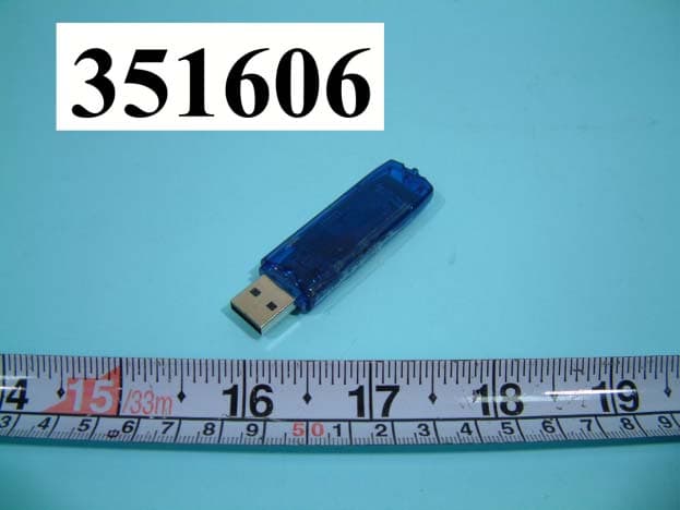
FI7BUB-103
Aug 25, 2003BLUETOOTH USB DONGLE
Equipment Class
DSS - Part 15 Spread Spectrum Transmitter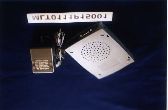
FI7MIEV56
Nov 28, 2001External 56K Data/Fax Modem
Equipment Class
JBP - Part 15 Class B Computing Device Peripheral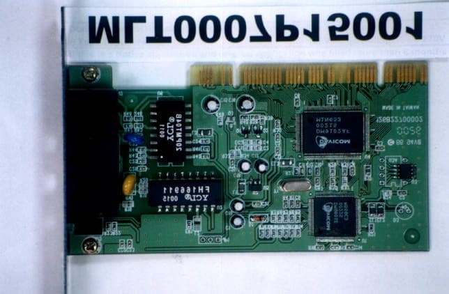
FI7PDIH00
Aug 09, 20001Mbps HomePNA & 10/100Mbpx Ethernet PCI Card
Equipment Class
JBP - Part 15 Class B Computing Device Peripheral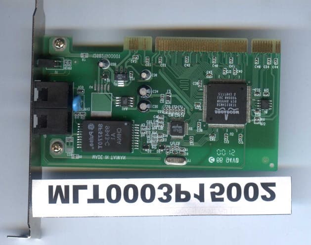
FI7PEIH00
Apr 25, 2000HomePNA 10Mbps PCI Card
Equipment Class
JBP - Part 15 Class B Computing Device Peripheral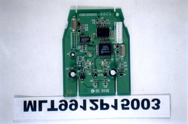
FI7R8ER00
Feb 07, 2000IC CARD READER
Equipment Class
JBP - Part 15 Class B Computing Device Peripheral