FI7MIEV56External 56K Data/Fax Modem
Archtek Telecom Corporation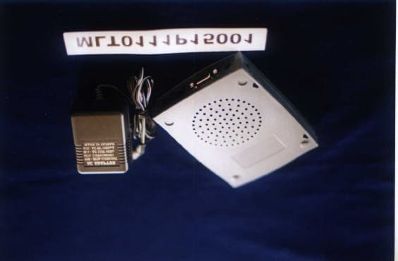
Click to zoom
Application Details
- Equipment Class
- JBP - Part 15 Class B Computing Device Peripheral
- Date of Grant
- Nov 28, 2001
- Application Purpose
- Original Equipment
- Date of Application
- Nov 28, 2001
- Equipment Note
- External 56K Data/Fax Modem
- Company
- Archtek Telecom Corporation
- Country
- Taiwan
Documents & Files
Document Text
Text extracted from the exhibit documents filed with the FCC. Open a document above to read the original.
Users Manual
1 IC+ 56K External Modem User’s Manual 2 Table Contents Table Contents.....................................................................................................2 Chapter 1 Installation.......................................................................................3 1. 1 Checking your components.............................................................3 1. 2 Installing the Modem........................................................................3 1. 3 Windows 95/98/ME/2000 Driver Installation ..............................5 1. 4 Windows NT4.0 Driver Installation ...............................................6 Chapter 2 AT commands set..........................................................................7 2. 1 Data Mode Command......................................................................8 2. 2 Result Code....................................................................................19 2. 3 S Registers Definitions.................................................................21 2. 4 Class 1 Fax Commands...............................................................28 2. 5 Voice Commands...........................................................................31 2. 6 AT% TTn Commands....................................................................33 3 Chapter 1 Installation Chapter 1 provides detailed instructions for installing your modem. 1.1 Checking your components Unpack your components and make sure you have the following items: l The modem. l A modular telephone cable to connect your modem to the telephone line. l This user's manual. l Communication software and manual. When you open your package, make sure all of the above items are included and not damaged. If you see that any components are damaged, please notify your dealer immediately. 1.2 Installing the modem The following instructions explain how to install the modem in a IBM compatible type personal computer. If you will be installing the modem into a different computer, refer to the manual that accompanied your computer or contact your computer dealer for instructions on installing the modem in your personal computer. Step 1 Connecting to a computer. Plug the male DB-9 connector on your RS-232 cable into the RS-232 connector on the back the modem. Step 2 Connecting to the telephone line Step 3 Connecting to your telephone Step 4 Connecting to an AC outlet 4 Step 5 Verifying your connection If you connected the modem to a computer, place the computer into terminal mode and complete the configuration information required by the software. Refer to your computer manual to find out the appropriate command to use. Then use the following procedure to verify that your connections: 1. Type AT and press the Enter key. If your system is operating properly, your modem sends an OK response to your screen and wait for your next command. If you did not receive a response, make sure your computer is sending commands to your modem. If this does not solve your problem, contact your computer dealer. 2. Use your communication software to prepare your computer to dial a call. Then type AT D x phone number, where x is either T for touch-tone dialing or P for pulse dialing and phone number is the telephone number that your modem is using. For example, if your modem is connected to the telephone line 555-2121 and Touch-Tone dialing is supported in your calling area, type ATDT 5552121. 3. Press the Enter key. You should receive a BUSY response and you should hear the busy signal through the modem speaker because the modem is calling itself. Your modem is now ready for operation. Refer to the manual that came with your communication software to begin communications. If you will be communicating directly with your modem, or if you want to find out more about the modem's operation, proceed to Chapter 2. 5 1.3 Windows 95/98/ME/2000 (PNP) Window 95/98 1. Boot the system. 2. Now Windows will begin the “Add New Hardware Wizard” and Search for new drivers for “IC+ 56k External Modem”. Click “Next”. 3. Select “Search for the best driver for your device. Click “Next”. 4. Than insert the driver installation CD into the CD-Rom. Click “Next”. 5. Windows driver file search for the device “IC+ 56k External Modem Pnp”. Click “Next”. 6. Click “Finish”. 7. After completed to copy the modem driver, the “New Hardware Found” will continue to complete the installation the “Voice Modem Serial Wave Device” for modem. Window ME 1. Boot the system. 2. Now Windows will begin the “Add New Hardware Wizard” and Search for new drivers for “IC+ 56k External Modem”. Click “Next”. 3. Select “Search for the best driver for your device. Click “Next”. 4. Than insert the driver installation CD into the CD-Rom. Click “Next”. 5. Windows driver file search for the device “IC+ 56k External Modem Pnp”. Click “Next”. 6. Click “Finish”. 7. After completed to copy the modem driver, the “New Hardware Found” will continue to complete the installation the “Voice Modem Serial Wave Device” for modem. Window 2000 1. Boot the system. 2. Now Windows will begin the “Found New Hardware Wizard”. Click “Next”. 3. Select “Search for a suitable driver for my device (recommended). Click “Next” button. 4. Please select “Specify a location” item and put driver disk into the CD-ROM. Click “Next”. 5. The wizard found a driver for the following device “IC+ 56k External Modem”. Click “Next”. 6. Windows finds your modem model “IC+ 56k External Modem Pnp”. Click on the “Finish” button if the displayed modem model name fits yours. 6 1.4 Windows NT4.0 1. Boot the system. 2. Double-Click Control Panel => Modems. 3. Click “Next”. 4. Click “Change...” then select “Have Disk...” button. 5. Select modem model “IC+ 56k External Modem” Click “Next”. 6. Click “Finish”. 7. Click “Close”. 8. Setup “RAS” to continue. 9. Restart the system. 10. Now you’ve completed to install the drivers for the modem. NOTE: Microsoft does not support plug and play in Windows NT 4.0. 7 Chaper 2 AT C…
Text truncated - open the document above for the full version.
External Photos
MAX LIGHT Report Number: MLT0111P15001 FCC ID: FI7MIEV56 Technology Lab MAX LIGHT Report Number: MLT0111P15001 FCC ID: FI7MIEV56 Technology Lab
ID Label/Location Info
MAX LIGHT Report Number: MLT0111P15001 FCC ID: FI7MIEV56 Technology Lab Label Format: Label Position: This device complies with Part15 of the FCC Rules. Operation is subject to the following two conditions: (1)This device may not cause harmful interference,and (2)This device must accept any interference received ,including. Interference that may cause undesired operation. Model : 56TPC FCC ID : FI7MIEV56 MADE IN TAIWAN Equipment Lable 3.5CMX6CM Rear View
Internal Photos
MAX LIGHT Report Number: MLT0111P15001 FCC ID: FI7MIEV56 Technology Lab MAX LIGHT Report Number: MLT0111P15001 FCC ID: FI7MIEV56 Technology Lab
Test Report
Product : External 56K Data/Fax Modem Manufacture : Archtek Telecom Corporation FCC ID : FI7MIEV56 Model : 56TPC Report No. : MLT0111P15001 Test Date : November 2.2001 Test By Max Light Technology Co.,Ltd. Room 5, 8F, No.125, Section 3 Roosevelt Road, Taipei, Taiwan., R.O.C. Tel: 886-2-2363-2447 Fax: 886-2-2363-2597 T T h h e e t t e e s s t t r r e e p p o o r r t t c c o o n n s s i i s s t t s s o o f f 1 1 p p a a g g e e s s i i n n t t o o t t a a l l . . I I t t m m a a y y b b e e d d u u p p l l i i c c a a t t e e d d c c o o m m p p l l e e t t e e l l y y f f o o r r l l e e g g a a l l u u s s e e w w i i t t h h t t h h e e a a l l l l o o w w a a n n c c e e o o f f t t h h e e a a p p p p l l i i c c a a n n t t . . I I t t s s h h a a l l l l n n o o t t b b e e r r e e p p r r o o d d u u c c e e d d e e x x c c e e p p t t i i n n f f u u l l l l , , w w i i t t h h o o u u t t t t h h e e w w r r i i t t t t e e n n a a p p p p r r o o v v a a l l o o f f o o u u r r l l a a b b o o r r a a t t o o r r y y . . MAX LIGHT MEASUREMENT REPORT Page: 2/21 Report Number: MLT0111P15001 FCC ID: FI7MIEV56 Technology Lab Table of Contents : I. General 4. II. Conducted Emissions Requirements 9. III. Radiated Emissions Requirements 13. Appendix I (EUT Test Setup) 18. MAX LIGHT MEASUREMENT REPORT Page: 3/21 Report Number: MLT0111P15001 FCC ID: FI7MIEV56 Technology Lab CERTIFICATION We here by verify that : The test data, data evaluation, test procedures and equipment configurations shown in this report were made in accordance with the procedures given in ANSI C63.4-1992. All test were conducted by MLT(Max Light Technology Co.,Ltd) Room 5, 8F, No.125, Section 3 Roosevelt Road, Taipei, Taiwan, R.O.C Also, we attest to the accuracy of each. We further submit that the energy emitted by the sample EUT tested as described in the report is in compliance with Class B radiated and conducted emission limit of FCC Rules Part 15 Subpart B. EUT : External 56K Data/Fax Modem Applicant : Archtek Telecom Corporation . 10F, NO. 110, SEC3, CHUNG-SHAN ROAD., CHUNG-HO, TAIPEI, 231 TAIWAN, R.O.C. Manufacturer : Archtek Telecom Corporation . 4F. No.9, Lane 130, Min- Chyuan Rd., Hsin-Tien , Taipei ,Taiwan Model No : 56TPC FCC ID : FI7MIEV56 Prepared by : Approved by : Country Huang Roger Chen MAX LIGHT MEASUREMENT REPORT Page: 4/21 Report Number: MLT0111P15001 FCC ID: FI7MIEV56 Technology Lab I. GENERAL 1.1 Introduction The following measurement report is submitted on behalf of Archtek Telecom Corporation. In support of a Class B Digital Device certification in accordance with Part2 Subpart J and Part 15 Subpart A And B of the Commission’s and Regulations. 1.2 Description of EUT EUT : External 56K Data/Fax Modem Applicant : Archtek Telecom Corporation . 4F. No.9, Lane 130, Min- Chyuan Rd., Hsin-Tien , Taipei ,Taiwan Manufacturer : Archtek Telecom Corporation . 4F. No.9, Lane 130, Min-Chyuan Rd., Hsin-Tien , Taipei ,Taiwan Model No : 56TPC FCC ID : FI7MIEV56 Power Type : Powered by AC Adaptor (9V AC,1.0A) Phone Cable : RJ-11Cx2(Nonshielded, 7’ long ,Plastic hoods) RS-232 Cable (9Pin) : RS-232 (9Pin) Connector x1(Shielded, 80cm long ) During testing the EUT was operated at Tx or Rx mode for each emission measured. This was done in order to ensure that maximum emission levels were attained. MAX LIGHT MEASUREMENT REPORT Page: 5/21 Report Number: MLT0111P15001 FCC ID: FI7MIEV56 Technology Lab 1.3 Description of Support Equipment In order to construct the minimum system which required by the ANSI C63.4-1991, following equipments were used as the support units. Computer : IBM Model No. : 16W Serial No. : BNC345M FCC ID : FCC DOC Keyboard : IBM Model No. : KB-9930 Serial No. : 09N5395 FCC ID : FCC DOC Monitor : IBM Model No. : 10L6145 030 Serial No. : 23-092079 FCC ID : Mouse : IBM Model No. : 0180-05N Serial No. : 23-96142 FCC ID : EMJMUSJJ Printer : PANASONIC Model No. : KX-P1080I Serial No. : 7CKAKE98933 FCC ID : ACJ5Z6KX-P10801 MAX LIGHT MEASUREMENT REPORT Page: 6/21 Report Number: MLT0111P15001 FCC ID: FI7MIEV56 Technology Lab Telephone : GE Model No. : 2-9240A Serial No. : 1943K MAX LIGHT MEASUREMENT REPORT Page: 7/21 Report Number: MLT0111P15001 FCC ID: FI7MIEV56 Technology Lab Power Supply PC Monitor Printer TEL Keyboard Mouse EUT RJ11C Cables RS-232 RS-232 To PSTN 1.4 Configuration of System Under Test During testing the EUT(External 56K Data/Fax Modem ) was connected to the IBM PC’s RS-232 port. So there is no need for additional I/O card. A mouse was connected to the mouse port and a printer was connected to the parallel port. A telephone set was connected to the Phone Jack of EUT and the Line Jack of EUT was connected to a simulator of PSTN. TEST SITE MAX LIGHT MEASUREMENT REPORT Page: 8/21 Report Number: MLT0111P15001 FCC ID: FI7MIEV56 Technology Lab 1.5 Test Procedure All measurements contained in this report were performed according to the techniques described in Measurement procedure ANSI C63.4-1992 "Measurement of unIntentional Radiators." 1.6 General Test Condition The conditions under which the EUT operates were varied to determine their effect on the equipment's emission characteristics. The final configuration of the test system and the mode of operation used during these tests was chosen as that which produced the highest emission levels. However, only those conditions which the EUT was considered likely to encounter in normal use were investigated. The system's radiated and conducted emissions were investigated while the computer alternately transferred data to the EUT as well as to the monitor and printer. Using a test program which sent a continuous stream of “H” characters to monitor and transferred data to and from the EUT was proven to worst case emissions. The system's physical layout and cabling was randomly arranged to ensure that maximum emission levels were attained. MAX LIGHT MEASUREMENT REPORT Page: 9/21 Report Number: MLT0111P15001 FCC ID: FI7MIEV56 Technology Lab II. Conducte…
Text truncated - open the document above for the full version.
Test Setup Photos
MAX LIGHT MEASUREMENT REPORT Page: 10/21 Report Number: MLT0111P15001 FCC ID: FI7MIEV56 Technology Lab 2.3 Test Configuration: Front View of The Test Configuration MAX LIGHT MEASUREMENT REPORT Page: 15/21 Report Number: MLT0111P15001 FCC ID: FI7MIEV56 Technology Lab 3.3 Test Configuration: Front View of The Test Configuration MAX LIGHT MEASUREMENT REPORT Page: 16/21 Report Number: MLT0111P15001 FCC ID: FI7MIEV56 Technology Lab Rear View of The Test Configuration MAX LIGHT MEASUREMENT REPORT Page: 11/21 Report Number: MLT0111P15001 FCC ID: FI7MIEV56 Technology Lab Rear View of The Test Configuration
Contact Information
Applicant
Mahan Chu(Vice President)
Test Firm
Max Light Technology Co., Ltd.Jesse Tien
Technical Specifications
| # | Rule Parts | Frequency Range | Power Output |
|---|---|---|---|
| 1 | 15B | - | - |
Other Applications from Archtek Telecom Corporation
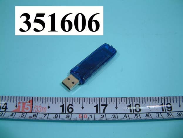
FI7BUB-103
Aug 25, 2003BLUETOOTH USB DONGLE
Equipment Class
DSS - Part 15 Spread Spectrum Transmitter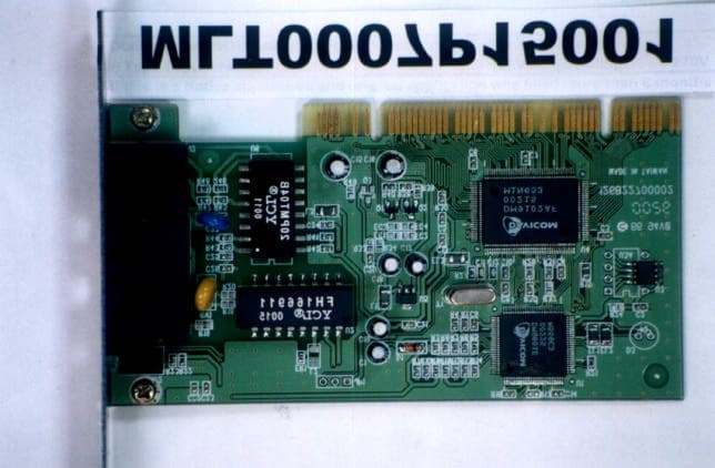
FI7PDIH00
Aug 09, 20001Mbps HomePNA & 10/100Mbpx Ethernet PCI Card
Equipment Class
JBP - Part 15 Class B Computing Device Peripheral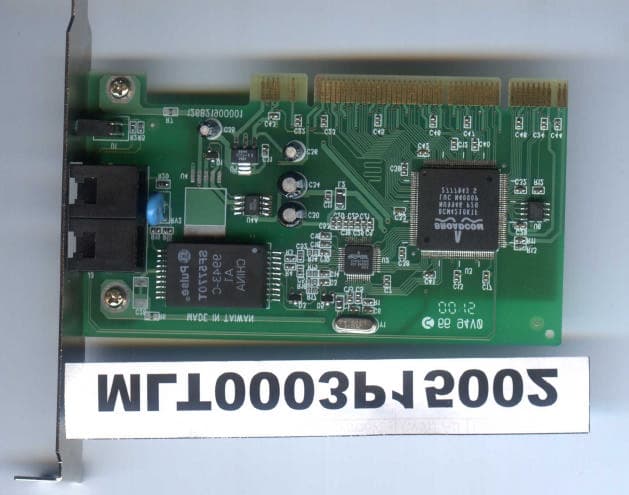
FI7PEIH00
Apr 25, 2000HomePNA 10Mbps PCI Card
Equipment Class
JBP - Part 15 Class B Computing Device Peripheral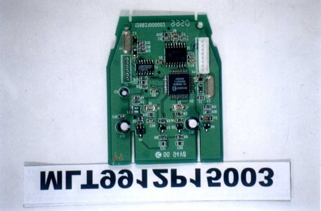
FI7R8ER00
Feb 07, 2000IC CARD READER
Equipment Class
JBP - Part 15 Class B Computing Device Peripheral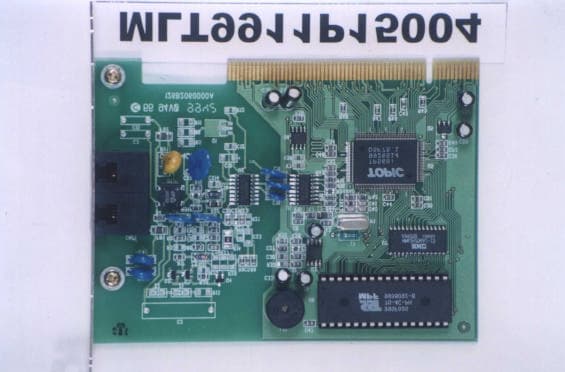
FI7MCIV56
Jan 13, 200056K Data/FAX Internal Modem
Equipment Class
JBP - Part 15 Class B Computing Device Peripheral