FI7R8ER00IC CARD READER
Archtek Telecom Corporation
Click to zoom
Application Details
- Equipment Class
- JBP - Part 15 Class B Computing Device Peripheral
- Date of Grant
- Feb 07, 2000
- Application Purpose
- Original Equipment
- Date of Application
- Jan 30, 2000
- Equipment Note
- IC CARD READER
- Company
- Archtek Telecom Corporation
- Country
- Taiwan
Documents & Files
Document Text
Text extracted from the exhibit documents filed with the FCC. Open a document above to read the original.
Users Manual
SmartLink SCR2000E Smart Card Reader Installation Manual A: Hardware Installation Connect to an available PS/2 connector of your PC. Then connect your PS/2 Mouse/Keyboard to the extension slot at the other side of the connector if necessary. Connect to an available 9-Pin com port. B. Driver Installation in Windows 98 environment. B-1 After connecting SmartLink SCR2000E, power your PC on, windows system will find the new hardware and will guide you to install the device driver. (As shown in the picture) Click “ Next > ” to continue. B-2 Select “Search for the best driver for your device.” option. And let Windows system to install the driver for you. Click “ Next > ” to continue. B-3 Select “Floppy disk drives” option. And insert the installation diskette into an available Floppy disk drive. Click “Next >” to continue. B-4 Windows will find the driver for “SmartLink SCR2000E Smart Card Reader”. Click “ Next > ” to continue. B-5 Windows has finished the installation of the driver. Click “Finish” to complete.
External Photos
MAX LIGHT Report Number: MLT9912P15003 FCC ID: FI7R8ER00 Technology Lab MAX LIGHT Report Number: MLT9912P15003 FCC ID: FI7R8ER00 Technology Lab MAX LIGHT Report Number: MLT9912P15003 FCC ID: FI7R8ER00 Technology Lab MAX LIGHT Report Number: MLT9912P15003 FCC ID: FI7R8ER00 Technology Lab
ID Label/Location Info
MAX LIGHT Report Number: MLT9912P15003 FCC ID: FI7R8ER00 Technology Lab Label Format: Label Position: This device complies with Part15 of the FCC Rules. Operation is subject to the following two conditions: (1) This device may not cause harmful interference,and (2) This device must accept any interference received ,including. Interference that may cause undesired operation. Model: SCR2000E FCC ID: FI7R8ER00 MADE IN TAIWAN Equipment Lable 1.5CMX2.5CM Rear View
Schematics
8 8 7 7 6 6 5 5 4 4 3 3 2 2 1 1 DD CC BB AA SMD1206 IFD SAM CONNECTOR E B C P3.3 = ICCSW (IC CARD SWITCH) ICCSW CS -> Vpp P1.0 CONTROL I/OP1.1 CONTROL RST ICC CONNECTOR 9 10 P3.4 CONTROL CS (SCK) 126B21000000 1. ̈ı 2. ©@ 3. æÔ 5. ∂¬ 4. ∂¿ 6. ∫Ò 7. ¬≈ 8. μμ SCR2000E.SCHA Smart Card Reader ARCHTEK TELECOM CORPORATION B 11Friday, December 17, 1999 Title SizeDocument NumberRev Date:Sheetof P2.0 P3.0RXP J10.4 P3.1 P2.1 P3.3 TXP RXP J10.4 J10.6 J10.7 J10.8 P1.0 P1.1 P1.2 P1.3 P1.4 P1.5 P1.7 P3.0 P3.1 I/O P3.3 P3.4 P3.5 P2.0 P2.1 VD CSRST I/OCLK P3.3 VD P1.2 P1.3 P1.5 CLK P3.3 P1.7 RSTI/O P1.1P1.0 CLK VD J10.8 TXP J10.7 J10.6 CLK1 CLK1 CS P3.4 P3.5 P1.4 VCC VCC VCC VCC VCC VCC VD VCC VCC VCC VD VDVDVD VCC R2 330 D1 LED R3 330 D2 LED R41K R5 1K R6 1K R7 10K C12 22PF/50V R12 1K F1FUSE 500mA C10 22PF/50V C20 NI C26 0.1uF C3 10U/6.3V Q4 2N3094 R1110K D3 1N4148 J1 HEADER 5X2 12 34 56 78 910 C5 0.1UF C11 0.1UF J7 CON6 1 2 3 4 5 6 P1 CON8 1 2 3 4 5 6 7 8 R18 10K R14 33 Ohm C8 0.1uF U1 MAX232 12 11 9 10 1 3 2 6 5 4 7 8 14 13 15 16 R1O T1I R2O T2I C1+ C1- V+ V- C2- C2+ T2O R2I T1O R1I GND VCC Q3 2N3904 Q2 2N3904 C22 NI Q1 SST4403 C18 0.1uF R8 10K C6 0.1UF R9 10K R1 10K C13 100uF\16V C7 0.1UF C1 22pF C21 NI C9 0.1uF C16 0.1uF R13 3.9K U5 W78E52F-24 40 41 42 43 44 1 2 3 5 7 8 9 10 11 12 13 18 19 20 21 22 23 24 25 37363534 4 33 32 29 30 31 14 15 16 17 38 27 26 28 6 39 P1.0 P1.1 P1.2 P1.3 P1.4 P1.5 P1.6 P1.7 P3.0 P3.1 P3.2 P3.3 P3.4 P3.5 P3.6 P3.7 P2.0 P2.1 P2.2 P2.3 P2.4 P2.5 P2.6 P2.7 P0.0P0.1P0.2P0.3 RST P0.4 P0.5 EA P0.7 P0.6 XTAL2 XTAL1 VSS NC VCC ALE PSEN NC NC NC U7A 74HC14 12 U7B 74HC14 34 Y1 3.579545MHZ U7E 74HC14 1110 R16 NI,1K C23 NI Q5 NI,2N3904 R17 NI,10K R15NI,10K U7F 74HC14 1312 U2A 74HC125 23 1 U2B 74HC125 56 4 C2 22pF C28 100PF C27 100PF Y2 11.0592MHZ L1 BEAD 600 R19 15 L2 BEAD 600 L3 BEAD 600
Test Report
Product : Smart Card Reader Applicant : Archtek Telecom Corporation. FCC ID : FI7R8ER00 Model : SCR2000E Report No. : MLT9912P15003 Test Date : December 25.1999 Test By Max Light Technology Co.,Ltd. Room 5, 8F, No.125, Section 3 Roosevelt Road, Taipei, Taiwan., R.O.C. Tel: 886-2-2363-2447 Fax: 886-2-2363-2597 T T h h e e t t e e s s t t r r e e p p o o r r t t c c o o n n s s i i s s t t s s o o f f 2 2 0 0 p p a a g g e e s s i i n n t t o o t t a a l l . . I I t t m m a a y y b b e e d d u u p p l l i i c c a a t t e e d d c c o o m m p p l l e e t t e e l l y y f f o o r r l l e e g g a a l l u u s s e e w w i i t t h h t t h h e e a a l l l l o o w w a a n n c c e e o o f f t t h h e e a a p p p p l l i i c c a a n n t t . . I I t t s s h h a a l l l l n n o o t t b b e e r r e e p p r r o o d d u u c c e e d d e e x x c c e e p p t t i i n n f f u u l l l l , , w w i i t t h h o o u u t t t t h h e e w w r r i i t t t t e e n n a a p p p p r r o o v v a a l l o o f f o o u u r r l l a a b b o o r r a a t t o o r r y y . . MAX LIGHT MEASUREMENT REPORT Page:2/20 Report Number: MLT9912P15003FCC ID: FI7R8ER00 Technology Lab Table of Contents : I. General 4. II. Conducted Emissions Requirements 8. III. Radiated Emissions Requirements 12. Appendix I (EUT Test Setup) 19. MAX LIGHT MEASUREMENT REPORT Page:3/20 Report Number: MLT9912P15003FCC ID: FI7R8ER00 Technology Lab CERTIFICATION We here by verify that : The test data, data evaluation, test procedures and equipment configurations shown in this report were made in accordance with the procedures given in ANSI C63.4-1992. All test were conducted by MLT(Max Light Technology Co.,Ltd) Room 5, 8F, No.125, Section 3 Roosevelt Road, Taipei, Taiwan, R.O.C Also, we attest to the accuracy of each. We further submit that the energy emitted by the sample EUT tested as described in the report is in compliance with Class B radiated and conducted emission limit of FCC Rules Part 15 Subpart B. EUT: Smart Card Reader Applicant: Archtek Telecom Corporation. 4F,No.9,Lane 130,Min-Chyuan Rd., Hsin-Tien,Taipei, Taiwan Manufacturer: Archtek Telecom Corporation. 4F,No.9,Lane 130,Min-Chyuan Rd., Hsin-Tien,Taipei, Taiwan Model No: SCR2000E FCC ID: FI7R8ER00 Prepared by :Approved by : Country Huang Roger Chen MAX LIGHT MEASUREMENT REPORT Page:4/20 Report Number: MLT9912P15003FCC ID: FI7R8ER00 Technology Lab I. GENERAL 1.1 Introduction The following measurement report is submitted on behalf of Archtek Telecom Corporation. In support of a Class B Digital Device certification in accordance with Part2 Subpart J and Part 15 Subpart A And B of the Commission’s and Regulations. 1.2 Description of EUT EUT: Smart Card Reader Applicant: Archtek Telecom Corporation. 4F,No.9,Lane 130,Min-Chyuan Rd., Hsin-Tien,Taipei, Taiwan Manufacturer: Archtek Telecom Corporation. 4F,No.9,Lane 130,Min-Chyuan Rd., Hsin-Tien,Taipei, Taiwan Model No: SCR2000E FCC ID : FI7R8ER00 Power Type: Powered by PC PS2 Cable: PS2 Connectorx1 (Shielded, 93 cm long) RS-232 Cable: 9Pin RS-232 Connectorx1 (Shielded, 65 cm long) During testing the EUT was operated at “Read data of IC Card” mode for each emission measured(P.S Run “Test Software” in Dos Mode). This was done in order to ensure that maximum emission levels were attained. MAX LIGHT MEASUREMENT REPORT Page:5/20 Report Number: MLT9912P15003FCC ID: FI7R8ER00 Technology Lab 1.3 Description of Support Equipment In order to construct the minimum system which required by the ANSI C63.4-1991, following equipments were used as the support units. Computer: COMPAQ Model No.: 3284 Serial No.: L708BKTB4154 FCC ID: EJH3284 Keyboard: COMPAQ Model No.: KPQ-E99ZC-13 Serial No.: 237743-334 FCC ID: CMYKPQ7285 Monitor: COMPAQ Model No.: 303U Serial No.: 704AG19TG099 FCC ID: BJMCM14UH Mouse: COMPAQ Model No.: 196694-301 Serial No.: 1SH67CHE03360 FCC ID: EMJMUSJJ Printer: PANASONIC Model No.: KX-P1080I Serial No.: 7CKAKE98933 FCC ID: ACJ5Z6KX-P10801 MAX LIGHT MEASUREMENT REPORT Page:6/20 Report Number: MLT9912P15003FCC ID: FI7R8ER00 Technology Lab 1.4 Configuration of System Under Test During testing the EUT(Smart Card Reader ) was connected to the Compaq PC’s PS2 port and RS-232 port. So there is no need for additional I/O card. A mouse was connected to the PS2 port of PC and a printer was connected to the parallel port of PC. A keyboard was connected to the other PS2 port of PC. Power Supply PC Monitor Printer Keyboard Mouse EUT RS-232 RS-232 PS2 Cable MAX LIGHT MEASUREMENT REPORT Page:7/20 Report Number: MLT9912P15003FCC ID: FI7R8ER00 Technology Lab 1.5 Test Procedure All measurements contained in this report were performed according to the techniques described in Measurement procedure ANSI C63.4-1992 "Measurement of unIntentional Radiators." 1.6 General Test Condition The conditions under which the EUT operates were varied to determine their effect on the equipment's emission characteristics. The final configuration of the test system and the mode of operation used during these tests was chosen as that which produced the highest emission levels. However, only those conditions which the EUT was considered likely to encounter in normal use were investigated. The system's radiated and conducted emissions were investigated while the EUT alternately transferred data (IC Card’s Data) to the computer. Run “Test Software” which read continuous data of IC Card form EUT . The EUT was proven to worst case emissions. The system's physical layout and cabling was randomly arranged to ensure that maximum emission levels were attained. MAX LIGHT MEASUREMENT REPORT Page:8/20 Report Number: MLT9912P15003FCC ID: FI7R8ER00 Technology Lab II. Conducted Emissions Requirements 2.1 General & Setup : The power line conducted emission measurements were performed in a shielded enclosure. The EUT was assembled on a wooden table which is 80 centimeters high, was placed 40 centimeters from the backwall and at least 1 meter from the sidewall. Power was fed to the EUT from the public utility power …
Text truncated - open the document above for the full version.
Contact Information
Applicant
Mahan Chu(Vice President)
Technical Contact
Max Light Technology Co.,LtdCountry Huang
[email protected]886-2-26633486
P.O.Box 5-86,Shen Keng · Taipei Hsien · Taiwan
Non-Technical Contact
Max Light Technology Co.,LtdCountry Huang
[email protected]886-2-26633486
Test Firm
Max Light Technology Co., Ltd.Jesse Tien
Technical Specifications
| # | Rule Parts | Frequency Range | Power Output |
|---|---|---|---|
| 1 | 15B | - | - |
Other Applications from Archtek Telecom Corporation
FI7BUB-103
Aug 25, 2003BLUETOOTH USB DONGLE
Equipment Class
DSS - Part 15 Spread Spectrum Transmitter
FI7MIEV56
Nov 28, 2001External 56K Data/Fax Modem
Equipment Class
JBP - Part 15 Class B Computing Device Peripheral
FI7PDIH00
Aug 09, 20001Mbps HomePNA & 10/100Mbpx Ethernet PCI Card
Equipment Class
JBP - Part 15 Class B Computing Device Peripheral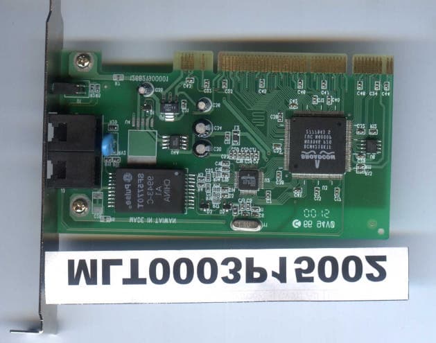
FI7PEIH00
Apr 25, 2000HomePNA 10Mbps PCI Card
Equipment Class
JBP - Part 15 Class B Computing Device Peripheral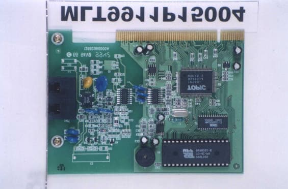
FI7MCIV56
Jan 13, 200056K Data/FAX Internal Modem
Equipment Class
JBP - Part 15 Class B Computing Device Peripheral