FI7MRIF56
Archtek Telecom Corporation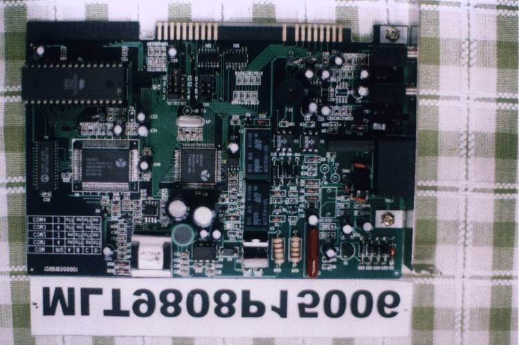
Click to zoom
Application Details
- Equipment Class
- JBP - Part 15 Class B Computing Device Peripheral
- Date of Grant
- Nov 30, 1998
- Application Purpose
- Original Equipment
- Date of Application
- Sep 30, 1998
- Company
- Archtek Telecom Corporation
- Country
- Taiwan
Documents & Files
Document Text
Text extracted from the exhibit documents filed with the FCC. Open a document above to read the original.
Users Manual
5634BIF User’s Manual 1 Congratulations on purchasing the most sophisticated modem available. Your modem combines advanced technology with state-of-the-art features to bring you the modern advanced communications device available today! This modem provides the following features. l Data modem − V.90 & K56flex − ITU-T V.34 (33.6 kbps), V.32 bis, V.32, V.22 bis, V.22, V.23, and V.21; Bell 212A and 103 − V.42 LAPM, MNP 2-4, MNP 10 error correction − V.42 bis and MNP 5 data compression l Fax modem send and receive rate up to 14400 bps − ITU-T V.17, V.29, V.27 ter, V.21 channel 2 − TIA/EIA 578 fax class 1 l V.80 synchronous access mode supports host-based communication protocols l World-class operation − Call progress − Blacklisting − Multiple country support l Voice/TAM mode l Full-duplex speakerphone (FDSP) mode l Audio Span simultaneous audio/voice and data (SP models) − ITU-T V.61 modulation (4.8 kbps data plus audio) l Flash memory support l Caller ID and distinctive ring detect Trademark Windows and MS-DOS are trademarks of Microsoft Corporation. IBM PC/AT is a trademark of International Business Machines. Other product or company names are trademarks or registered trademarks of their respective holders. 5634BIF User’s Manual 2 Table of Contents CHAPTER 1 INSTALLING THE MODEM.............................................................4 1.1 CHECKING YOUR COMPONENTS.............................................................................4 1.2 WHAT ELSE YOU NEED...........................................................................................4 1.3 INSTALLING THE MODEM.........................................................................................4 1.4 REMOVING THE COMPUTER COVER........................................................................4 1.5 SETTING THE MODEM SWITCHES............................................................................4 1.6 INSERTING THE MODEM..........................................................................................7 1.7 CONNECTING TO THE TELEPHONE LINE..................................................................7 1.8 CONNECTING TO YOUR FAX MACHINE....................................................................8 1.9 CONNECTING TO THE MICROPHONE AND SPEAKER.................................................8 1.10 VERIFYING YOUR CONNECTION.............................................................................8 CHAPTER 2 TYPING COMMANDS AND RECEIVING RESPONSES.............10 2.1 TYPING A COMMAND.............................................................................................10 2.2 TO TYPE A COMMAND LINE :..................................................................................10 2.3 CORRECTING A TYPING MISTAKE..........................................................................10 2.4 READABILITY........................................................................................................10 2.5 TYPING MORE THAN 40 CHARACTERS..................................................................10 2.6 OMITTING A PARAMETER.......................................................................................11 2.7 REPEATING A COMMAND LINE...............................................................................11 2.8 MODEM RESPONSES............................................................................................11 2.9 WORD OR NUMERIC RESPONSES.........................................................................12 2.9.1 X0 response set..........................................................................................12 2.9.2 X1 response set..........................................................................................12 2.9.3 X2 response set..........................................................................................12 2.9.4 X3 response set..........................................................................................12 2.9.5 X4 response set..........................................................................................13 2.10 CORRECTION & COMPRESSION RESPONSES......................................................13 CHAPTER 3 USING CONFIGURATION PROFILES..........................................17 3.1 STORING A PROFILE.............................................................................................17 3.2 RECALLING A PROFILE..........................................................................................17 3.3 RESET AND RECALLING PROFILE...........................................................................18 CHAPTER 4 ERROR CORRECTION AND DATA COMPRESSION.................19 4.1 ERROR-CORRECTION PROTOCOLS.......................................................................19 4.2 V.42.....................................................................................................................19 4.3 CONFIGURING FOR AUTO-RELIABLE OPERATION...................................................19 4.4 CONFIGURING FOR RELIABLE OPERATION.............................................................20 4.5 TURNING OFF ERROR-CORRECTION.....................................................................20 4.6 MNP5 AND V.42BIS DATA-COMPRESSION...........................................................20 CHAPTER 5 LIST OF MODEM COMMANDS....................................................21 CHAPTER 6 .........................................................LIST OF MODEM S-REGISTER29 6.1 READING AN S-REGISTER VALUE.........................................................................29 6.2 CHANGING AN S-REGISTER VALUE.......................................................................29 6.3 S-REGISTER DESCRIPTIONS.................................................................................29 5634BIF User’s Manual 3 CHAPTER 7 HARDWARE QUICK INSTALLATION GUIDE (INTERNAL NON-PNP)43 7.1 FOR WINDOWS 95.........................................................................................…
Text truncated - open the document above for the full version.
Block Diagram
MAX LIGHT Report Number: MLT9808P15006FCC ID: FI7MRIF56 Technology Lab
External Photos
MAX LIGHT Report Number: MLT9808P15006FCC ID: FI7MRIF56 Technology Lab MAX LIGHT Report Number: MLT9808P15006FCC ID: Technology Lab MAX LIGHT Report Number: MLT9808P15006FCC ID: Technology Lab
ID Label/Location Info
MAX LIGHT MAX LIGHT MAX LIGHT MAX LIGHT Technology Lab Label Format: Label Position: This device complies with Part15 of the FCC Rules. Operation is subject to the following two conditions: (1) This device may not cause harmful interference,and (2) This device must accept any interference received ,including. Interference that may cause undesired operation. Model: 5634BIF FCC ID: FI7MRIF56 MADE IN TAIWAN Equipment Lable 4CMX3CM Rear View
Schematics
MAX LIGHT Report Number: MLT9808P15006FCC ID: FI7MRIF56 Technology Lab MAX LIGHT Report Number: MLT9808P15006FCC ID: Technology Lab MAX LIGHT Report Number: MLT9808P15006FCC ID: Technology Lab MAX LIGHT Report Number: MLT9808P15006FCC ID: Technology Lab MAX LIGHT Report Number: MLT9808P15006FCC ID: Technology Lab
Test Report
Product : 56K Internal Modem Manufacture : Archtek Telecom Corporation FCC ID : FI7MRIF56 Model : 5634BIF Report No. : MLT9808P15006 Test Date : 09/20/1998 Test By Max Light Technology Co.,Ltd. Room 5, 8F, No.125, Section 3 Roosevelt Road, Taipei, Taiwan., R.O.C. Tel: 886-2-2363-2447 Fax: 886-2-2363-2597 MAX LIGHT MEASUREMENT REPORT Page: 2 Report Number: MLT9808P15006FCC ID: FI7MRIF56 Technology Lab Table of Contents : I. General 4. II. Conducted Emissions Requirements 9. III. Radiated Emissions Requirements 14. Appendix I (EUT Test Setup) 20. MAX LIGHT MEASUREMENT REPORT Page: 3 Report Number: MLT9808P15006FCC ID: FI7MRIF56 Technology Lab CERTIFICATION We here by verify that : The test data, data evaluation, test procedures and equipment configurations shown in this report were made in accordance with the procedures given in ANSI C63.4-1992. All test were conducted by MLT(Max Light Technology Co.,Ltd) Room 5, 8F, No.125, Section 3 Roosevelt Road, Taipei, Taiwan, R.O.C Also, we attest to the accuracy of each. We further submit that the energy emitted by the sample EUT tested as described in the report is in compliance with Class B radiated and conducted emission limit of FCC Rules Part 15 Subpart B. EUT: 56K Internal Modem Applicant: Archtek Telecom Corporation . 4F. No.9, Lane 130, Min-Chyuan Rd., Hsin-Tien , Taipei ,Taiwan Manufacturer: Archtek Telecom Corporation . 4F. No.9, Lane 130, Min-Chyuan Rd., Hsin-Tien , Taipei ,Taiwan Model No: 5634BIF FCC ID: FI7MRIF56 Prepared by : Country Approved by : Roger Country Huang Roger Chen MAX LIGHT MEASUREMENT REPORT Page: 4 Report Number: MLT9808P15006FCC ID: FI7MRIF56 Technology Lab I. GENERAL 1.1 Introduction The following measurement report is submitted on behalf of Archtek Telecom Corporation. In support of a Class B Digital Device certification in accordance with Part2 Subpart J and Part 15 Subpart A And B of the Commission’s and Regulations. 1.2 Description of EUT EUT: 56K Internal Modem Applicant: Archtek Telecom Corporation . 4F. No.9, Lane 130, Min-Chyuan Rd., Hsin-Tien , Taipei , Taiwan Manufacturer: Archtek Telecom Corporation . 4F. No.9, Lane 130, Min-Chyuan Rd., Hsin-Tien , Taipei , Taiwan Model No: 5634BIF FCC ID : FI7MRIF56 Power Type: Powered by PC Phone Cable: RJ-11Cx2(Nonshielded, 7’ long ,Plastic hoods) During testing the EUT was operated at Tx or Rx mode for each emission measured. This was done in order to ensure that maximum emission levels were attained. MAX LIGHT MEASUREMENT REPORT Page: 5 Report Number: MLT9808P15006FCC ID: FI7MRIF56 Technology Lab 1.3 Description of Support Equipment In order to construct the minimum system which required by the ANSI C63.4-1991, following equipments were used as the support units. Computer: COMPAQ Model No.: 3284 Serial No.: L708BKTB4154 FCC ID: EJH3284 Keyboard: COMPAQ Model No.: KPQ-E99ZC-13 Serial No.: 237743-334 FCC ID: CMYKPQ7285 Monitor: COMPAQ Model No.: 303U Serial No.: 704AG19TG099 FCC ID: BJMCM14UH Mouse: COMPAQ Model No.: 285728-001 Serial No.: 97033491 FCC ID: FSUGMZE4 Printer: PANASONIC Model No.: KX-P1080I Serial No.: 7CKAKE98933 FCC ID: ACJ5Z6KX-P10801 PSTN Simulator: MLT Model No.: 1101 Serial No.: N/A MAX LIGHT MEASUREMENT REPORT Page: 6 Report Number: MLT9808P15006FCC ID: FI7MRIF56 Technology Lab Telephone: GE Model No.: 2-9240A Serial No.: 1943K Speaker: KAKA Model No.: 2K-A01 Serial No.: 189665 Microphone: Ever Power Model No.: TC-944 Serial No.: N/A Modem: Askey (External Fax / Data Modem) Model No.: WS1414SV Serial No.: IAH-10811 MAX LIGHT MEASUREMENT REPORT Page: 7 Report Number: MLT9808P15006FCC ID: FI7MRIF56 Technology Lab 1.4 Configuration of System Under Test During testing the EUT(Data/Fax Modem card) install in the Compaq PC. So there is no need for additional I/O card. A mouse was connected to the mouse port and a printer was connected to the parallel port. There is one serial port. A external modem connected the serial port and the external modem connected with two unterminated telephone cables on the line and phone jack. A telephone set was connected to the Phone Jack of EUT and the Line Jack of EUT was connected to a simulator of PSTN. Power Supply PC Monitor Printer PSTN Keyboard Mouse EUT Telephone RJ11C Cables RS-232RS-232 MAX LIGHT MEASUREMENT REPORT Page: 8 Report Number: MLT9808P15006FCC ID: FI7MRIF56 Technology Lab 1.5 Test Procedure All measurements contained in this report were performed according to the techniques described in Measurement procedure ANSI C63.4-1992 "Measurement of unIntentional Radiators." 1.6 General Test Condition The conditions under which the EUT operates were varied to determine their effect on the equipment's emission characteristics. The final configuration of the test system and the mode of operation used during these tests was chosen as that which produced the highest emission levels. However, only those conditions which the EUT was considered likely to encounter in normal use were investigated. The system's radiated and conducted emissions were investigated while the computer alternately transferred data to the EUT as well as to the monitor and printer. Using a test program which sent a continuous stream of “H” characters to monitor and transferred data to and from the EUT was proven to worst case emissions. The system's physical layout and cabling was randomly arranged to ensure that maximum emission levels were attained. MAX LIGHT MEASUREMENT REPORT Page: 9 Report Number: MLT9808P15006FCC ID: FI7MRIF56 Technology Lab II. Conducted Emissions Requirements 2.1 General & Setup : The power line conducted emission measurements were performed in a shielded enclosure. The EUT was assembled on a wooden table which is 80 centimeters high, was placed 40 centimeters from the backwall and at least 1 meter from the sidewall. Power was fed to the EUT from the public utility power grid through a line filter and EMCO Model 3825/2 Line Impedance Stabilization Networks (LISN). The LISN housing, measuring instrumentation case, ground …
Text truncated - open the document above for the full version.
Test Report
Product : 56K Internal Modem Manufacture : Archtek Telecom Corporation FCC ID : FI7MRIF56 Model : 5634BIF Report No. : MLT9808P15006 Test Date : 09/20/1998 Test By Max Light Technology Co.,Ltd. Room 5, 8F, No.125, Section 3 Roosevelt Road, Taipei, Taiwan., R.O.C. Tel: 886-2-2363-2447 Fax: 886-2-2363-2597 MAX LIGHT MEASUREMENT REPORT Page: 2 Report Number: MLT9808P15006FCC ID: FI7MRIF56 Technology Lab Table of Contents : I. General 4. II. Conducted Emissions Requirements 9. III. Radiated Emissions Requirements 14. Appendix I (EUT Test Setup) 20. MAX LIGHT MEASUREMENT REPORT Page: 3 Report Number: MLT9808P15006FCC ID: FI7MRIF56 Technology Lab CERTIFICATION We here by verify that : The test data, data evaluation, test procedures and equipment configurations shown in this report were made in accordance with the procedures given in ANSI C63.4-1992. All test were conducted by MLT(Max Light Technology Co.,Ltd) Room 5, 8F, No.125, Section 3 Roosevelt Road, Taipei, Taiwan, R.O.C Also, we attest to the accuracy of each. We further submit that the energy emitted by the sample EUT tested as described in the report is in compliance with Class B radiated and conducted emission limit of FCC Rules Part 15 Subpart B. EUT: 56K Internal Modem Applicant: Archtek Telecom Corporation . 4F. No.9, Lane 130, Min-Chyuan Rd., Hsin-Tien , Taipei ,Taiwan Manufacturer: Archtek Telecom Corporation . 4F. No.9, Lane 130, Min-Chyuan Rd., Hsin-Tien , Taipei ,Taiwan Model No: 5634BIF FCC ID: FI7MRIF56 Prepared by : Country Approved by : Roger Country Huang Roger Chen MAX LIGHT MEASUREMENT REPORT Page: 4 Report Number: MLT9808P15006FCC ID: FI7MRIF56 Technology Lab I. GENERAL 1.1 Introduction The following measurement report is submitted on behalf of Archtek Telecom Corporation. In support of a Class B Digital Device certification in accordance with Part2 Subpart J and Part 15 Subpart A And B of the Commission’s and Regulations. 1.2 Description of EUT EUT: 56K Internal Modem Applicant: Archtek Telecom Corporation . 4F. No.9, Lane 130, Min-Chyuan Rd., Hsin-Tien , Taipei , Taiwan Manufacturer: Archtek Telecom Corporation . 4F. No.9, Lane 130, Min-Chyuan Rd., Hsin-Tien , Taipei , Taiwan Model No: 5634BIF FCC ID : FI7MRIF56 Power Type: Powered by PC Phone Cable: RJ-11Cx2(Nonshielded, 7’ long ,Plastic hoods) During testing the EUT was operated at Tx or Rx mode for each emission measured. This was done in order to ensure that maximum emission levels were attained. MAX LIGHT MEASUREMENT REPORT Page: 5 Report Number: MLT9808P15006FCC ID: FI7MRIF56 Technology Lab 1.3 Description of Support Equipment In order to construct the minimum system which required by the ANSI C63.4-1991, following equipments were used as the support units. Computer: COMPAQ Model No.: 3284 Serial No.: L708BKTB4154 FCC ID: EJH3284 Keyboard: COMPAQ Model No.: KPQ-E99ZC-13 Serial No.: 237743-334 FCC ID: CMYKPQ7285 Monitor: COMPAQ Model No.: 303U Serial No.: 704AG19TG099 FCC ID: BJMCM14UH Mouse: COMPAQ Model No.: 285728-001 Serial No.: 97033491 FCC ID: FSUGMZE4 Printer: PANASONIC Model No.: KX-P1080I Serial No.: 7CKAKE98933 FCC ID: ACJ5Z6KX-P10801 PSTN Simulator: MLT Model No.: 1101 Serial No.: N/A MAX LIGHT MEASUREMENT REPORT Page: 6 Report Number: MLT9808P15006FCC ID: FI7MRIF56 Technology Lab Telephone: GE Model No.: 2-9240A Serial No.: 1943K Speaker: KAKA Model No.: 2K-A01 Serial No.: 189665 Microphone: Ever Power Model No.: TC-944 Serial No.: N/A Modem: Askey (External Fax / Data Modem) Model No.: WS1414SV Serial No.: IAH-10811 MAX LIGHT MEASUREMENT REPORT Page: 7 Report Number: MLT9808P15006FCC ID: FI7MRIF56 Technology Lab 1.4 Configuration of System Under Test During testing the EUT(Data/Fax Modem card) install in the Compaq PC. So there is no need for additional I/O card. A mouse was connected to the mouse port and a printer was connected to the parallel port. There is one serial port. A external modem connected the serial port and the external modem connected with two unterminated telephone cables on the line and phone jack. A telephone set was connected to the Phone Jack of EUT and the Line Jack of EUT was connected to a simulator of PSTN. Power Supply PC Monitor Printer PSTN Keyboard Mouse EUT Telephone RJ11C Cables RS-232RS-232 MAX LIGHT MEASUREMENT REPORT Page: 8 Report Number: MLT9808P15006FCC ID: FI7MRIF56 Technology Lab 1.5 Test Procedure All measurements contained in this report were performed according to the techniques described in Measurement procedure ANSI C63.4-1992 "Measurement of unIntentional Radiators." 1.6 General Test Condition The conditions under which the EUT operates were varied to determine their effect on the equipment's emission characteristics. The final configuration of the test system and the mode of operation used during these tests was chosen as that which produced the highest emission levels. However, only those conditions which the EUT was considered likely to encounter in normal use were investigated. The system's radiated and conducted emissions were investigated while the computer alternately transferred data to the EUT as well as to the monitor and printer. Using a test program which sent a continuous stream of “H” characters to monitor and transferred data to and from the EUT was proven to worst case emissions. The system's physical layout and cabling was randomly arranged to ensure that maximum emission levels were attained. MAX LIGHT MEASUREMENT REPORT Page: 9 Report Number: MLT9808P15006FCC ID: FI7MRIF56 Technology Lab II. Conducted Emissions Requirements 2.1 General & Setup : The power line conducted emission measurements were performed in a shielded enclosure. The EUT was assembled on a wooden table which is 80 centimeters high, was placed 40 centimeters from the backwall and at least 1 meter from the sidewall. Power was fed to the EUT from the public utility power grid through a line filter and EMCO Model 3825/2 Line Impedance Stabilization Networks (LISN). The LISN housing, measuring instrumentation case, ground …
Text truncated - open the document above for the full version.
Contact Information
Applicant
Mahan Chu(Vice President)
Technical Contact
Max Light Technology Co.,LtdCountry Huang
[email protected]886-2-26633486
P.O.Box 5-86,Shen Keng · Taiwan
Non-Technical Contact
Max Light Technology Co.,LtdCountry Huang
[email protected]886-2-26633486
Technical Specifications
| # | Rule Parts | Frequency Range | Power Output |
|---|---|---|---|
| 1 | 15B | - | - |
Other Applications from Archtek Telecom Corporation
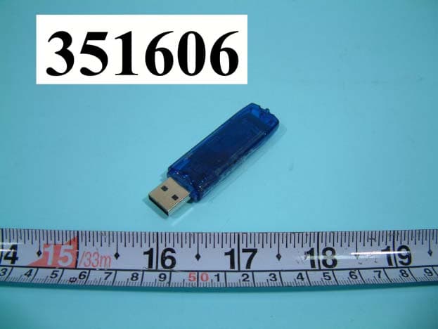
FI7BUB-103
Aug 25, 2003BLUETOOTH USB DONGLE
Equipment Class
DSS - Part 15 Spread Spectrum Transmitter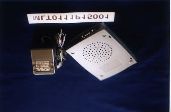
FI7MIEV56
Nov 28, 2001External 56K Data/Fax Modem
Equipment Class
JBP - Part 15 Class B Computing Device Peripheral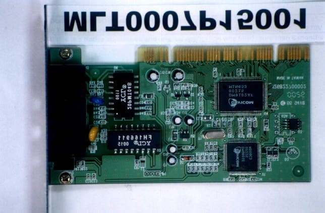
FI7PDIH00
Aug 09, 20001Mbps HomePNA & 10/100Mbpx Ethernet PCI Card
Equipment Class
JBP - Part 15 Class B Computing Device Peripheral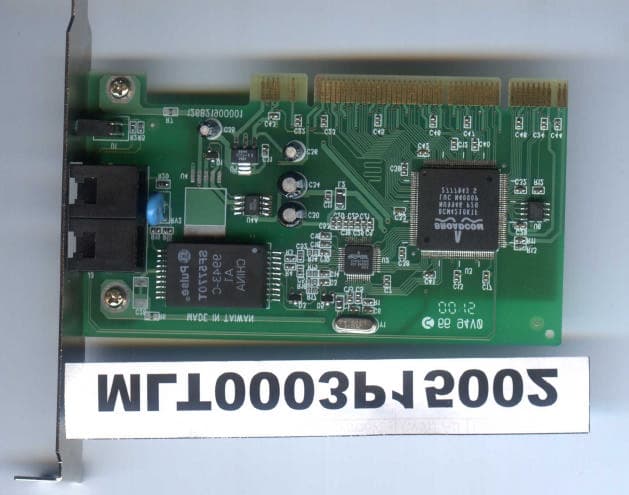
FI7PEIH00
Apr 25, 2000HomePNA 10Mbps PCI Card
Equipment Class
JBP - Part 15 Class B Computing Device Peripheral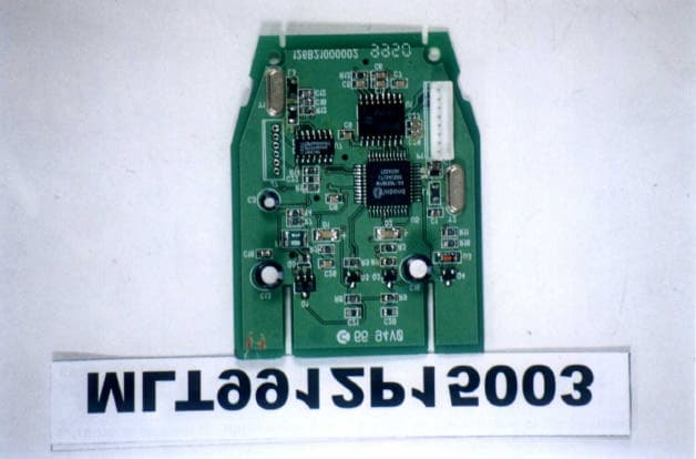
FI7R8ER00
Feb 07, 2000IC CARD READER
Equipment Class
JBP - Part 15 Class B Computing Device Peripheral