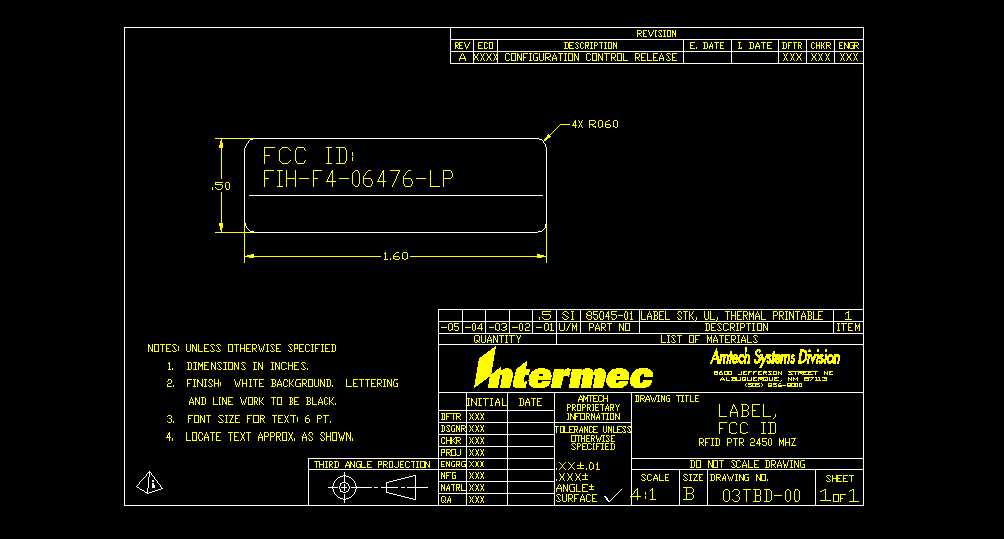
FIH-F4-06476-LPRFID Bar Code Printer
TransCoreApplication Details
- Equipment Class
- DSS - Part 15 Spread Spectrum Transmitter
- Date of Grant
- Aug 07, 2000
- Application Purpose
- Original Equipment
- Date of Application
- Apr 30, 2000
- Equipment Note
- RFID Bar Code Printer
- Frequency Range
- 2402.00000000 - 2480.00000000
- Company
- TransCore
- Country
- United States
Documents & Files
Document Text
Text extracted from the exhibit documents filed with the FCC. Open a document above to read the original.
Users Manual
Chapter 1 Introduction Safety Requirements Product Labeling Intermec assumes no responsibility as regards fulfilling the CE Directive if the printer is handled, modified or installed in any way other than that described in Intermec's manuals. Caution • Read this manual carefully before connecting the printer. • Moving parts are exposed when the side door is open, so ensure • that the door is closed before you operate the printer. • Do not open the front/left-hand cover. Dangerous voltage! • Do not remove the bottom plate. Dangerous voltage! • Do not put your fingers inside the print mechanism when the power is on. • Do not operate printer with side door open or feed plate removed. • Place the printer on an even surface which can support its weight of approximately 7 kgs (15.5 lbs) plus supplies. • Do not spray the printer with water. If using a hose to clean the premises in an industrial environment, remove the printer or protect it carefully from spray and moisture. • Carefully read the warning text on the envelope before using a cleaning card. The machine sign is attached to the printer's rear plate and contains information on type, model and serial number as well as main voltage. It also contains various signs of approval. 8Intermec EasyCoder F4-Installation & Operation Ed. 2
Cover Letter(s)
Inte rme c Te chnologie s Corporation Amtech Systems Division 8600 Jefferson St. NE Albuquerque, NM 87113 Phone: (505) 856-8054 Fax: (505) 857-0715 May 2, 2000 E- ma il: wma ys @ a s c tmd . c o m Federal Communications Commission Equipment Authorization Division 7435 Oakland Mills Road Columbia, MD 21046 RE:Request for Confidential Treatment FCC ID No: FIH-F4-06476-LP Dear Sirs: Amtech Systems Division of Intermec Technologies Corp. requests that the materials in the Block Diagram, Schematics, and Operational Description be withheld from public disclosure in accordance with Section 0.459 of the Commission’s Rules, 47 C.F.R. § 0.459 (1998), following grant of the application. In support of this request, Intermec submits the following: (1) identification of the specific information for which confidential treatment is sought: The materials set forth in the Operational Description, Block Diagram and Schematics, which are segregated from the non-confidential exhibits of the application, are those for which confidentiality is sought. (2) identification of the Commission proceeding in which the information was submitted or a description of the circumstances giving rise to the submission: The proceeding is that involving the application for equipment authorization (certification) under FCC ID No.: FIH-F4-06476-LP (3) explanation of the degree to which the information is commercial or financial, or contains a trade se cre t or is privile ge d: This material includes detailed theory of operation and circuit diagrams (schematics and blocks). As such, this material is treated as highly confidential business information (4) explanation of the degree to which the information concerns a service that is subject to competition: The material for w hich confidentiality is sought is employed in the design and manufacture of Location and Monitoring Service transmitting equipment that is offered on a highly competitive basis. Customers for this equipment have a variety of competing sources of supply. (5) e xplanation of how disclosure of the information could re sult in substantial compe titive harm: Disclosure would, in effect, give away the fruits of the labors of Intermec’s engineering personnel, who have designed the equipment and the manufacturing processes. Disclosure would also offer competitors additional unwarranted insight into the state of product development thereby allowing such competitors an advantage that would not be available to Intermec. page 2 (6) ide ntification of any me asure s take n by the submitting party to pre ve nt unauthoriz e d disclosure : The information for w hich confidential treatment is sought is kept confidential by Intermec and not made available to third parties except pursuant to non-disclosure agreements. (7) identification of whether the information is available to the public and the extent of any previous disclosure of the information to third partie s: To the knowledge of those preparing this application, the information has not been disclosed publicly heretofore. While the general theory of operation of this non-multilateration equipment has been the subject of numerous disclosures in industry and standards groups as well as in rule making proceedings at the FCC, the protection sought is narrow ly draw n and pertains to certain specific implementations of modulated backscatter radio technology. (8) justification of the period during which the submitting party asserts that material should not be available for public disclosure : This material should not be disclosed for at least 25 years. While improvements in design are made relatively frequently, disclosure of the design information would lead to insights into both designs and manufacturing techniques and could have an adverse competitive effect for many years to come. This equipment is designed for commercial, industrial, and governmental transportation applications. As such, unlike most consumer equipment, it is expected to be used for more than a decade in some cases. Moreover, this equipment will be used in revenue collection (e.g. toll collections) and secure access control applications (e.g. freight handling facilities). As such, it is important that its design not be made available to unauthorized persons who might attempt to use knowledge of the design to compromise the applications for which the equipment will be employed. (9) any other information that the party seeking confidential treatment believes may be useful in assessing whether its request for confidentiality should be granted: See item 8 above. Note that the equipment for which approval is being sought will be employed in applications that inherently carry a premium on security. Respectfully, Wesley M. Mays Engineering Manager Amtech Systems Division Intermec Technologies Corporation
Cover Letter(s)
Inte rme c Te chnologie s Corporation Amtech Systems Division 8600 Jefferson St. NE Albuquerque, NM 87113 Phone: (505) 856-8054 Fax: (505) 857-0715 May 2, 2000 E- ma il: wma ys @ a s c tmd . c o m Federal Communications Commission Equipment Authorization Division 7435 Oakland Mills Road Columbia, MD 21046 RE:Request for Confidential Treatment of Block Diagram FCC ID No: FIH-F4-06476-LP Dear Sirs: The block diagram for the F4 RFID printer is considered by Amtech to be confidential information. The file transmitted to the Commission is marked “Amtech Confidential Information”; unfortunately, the confidential flag on the web page was (inadvertently) not marked as such. A separate request for confidentiality (including the block diagram) has been transmitted to the Commission. Please treat this drawing as confidential. Respectfully, Wesley M. Mays Engineering Manager Amtech Systems Division Intermec Technologies Corporation
Cover Letter(s)
Inte rme c Te chnologie s Corporation Amtech Systems Division 8600 Jefferson St. NE Albuquerque, NM 87113 Phone: (505) 856-8054 Fax: (505) 857-0715 June 12, 2000 E- ma il: wma ys @ a s c tmd . c o m Federal Communications Commission Equipment Authorization Division 7435 Oakland Mills Road Columbia, Maryland 20146 Re: Amtech Systems Division of Intermec Technologies Corp. Amendment to Application for Equipment Authorization Proposed FCC I.D. No. FIH-F4-06476-LP Correspondence Reference Number:14398 `731 Confirmation Number: EA97485 To the Commission: In response to your e-mail transmitted to Amtech on 6/5/00 from Mr. Errol Chang (Ref. No. 14398), concerning the pending grant of certification of the F4 printer (operating as a frequency hopping radio in the 2400-2483.5 MHz band), we are submitting the following amendments and clarifications to our application as described herein: 1. Minimum Channel Separation requirement 15.247(a)(1): The μP module programs the frequency hopping source in a pre-determined pattern in accordance with the pseudo random sequence outlined in the IEEE 802.11 standard. A phased locked loop (PLL) source synthesizes the 79 discrete frequencies (channels) in the 2402 – 2480 MHz band. This produces a channel separation of 1 MHz. 2. Channel Occupancy 15.247(a)(1)(ii): The hopping time is controlled by the μP module that commands the synthesized PLL source to provide a single RF signal. Each hop time is set to be 381 mS by the timing circuitry in the μP. Therefore, with the 79 discrete frequencies, the channel occupancy meet the 30 second period as specified in §15.247(a)(1)(ii). 3. Peak Power (15.247(b)(2): The transmitter power measurement was inadvertently omitted from the test report by Rogers Labs, Inc. A Test Report Addendum prepared by Rogers Labs, Inc. shows that the peak power is 129.17 dBμV. A 6 dB attenuator used in the measurement system produces a signal of 135.17 dBμV (28.17 dBm or 0.66 watts) at the device terminal. This measurement was performed at the mid band frequency of 2441 MHz. The Test Report Addendum has been transmitted to the commission under separate cover. page 2 4. Input bandwidth of the receiver matches that of the transmitter §15.247(a)(1) The reader communicates with the tag through a spread spectrum, frequency hopping signal. The reader modulates the carrier that is decoded by the tag. The tag then imposes modulation upon the carrier and reflects the carrier (modulated backscatter) to the reader. The receiver operates in a homodyne mode. The received signals pass through a pre-selector filter designed to eliminate high frequency interference including the harmonics generated in the transmitter. The local oscillator used in the receiver is the same frequency hopping oscillator used to generate the carrier signal that is transmitted to the tag, modulated by the tag, and back scattered to the receiver. Therefore, both signals are hopping at exactly the same frequency. Since the receiver operates simultaneously with the reader transmission, the system receiver will shift frequency in synch with the transmitter signal. The received signals are directly converted to baseband in the homodyne. The down converted signals are band limited by a series of active filters that provide a 3 dB pass band of approximately 6 kHz to 120 kHz. The filters provide the receiver with a 20 dB IF bandwidth of 400 kHz. Since each received signal is down converted and band limited at baseband, the IF bandwidth, and hence the front end bandwidth of the receiver, exactly match the transmitted signal from the tag. Thank you for bringing these deficiencies in our application to our attention. Please contact me if there are any additional questions. I may be reached by email at [email protected] or by phone at (505) 856-8054. Sincerely, Wes Mays Manager, Microwave Design
External Photos
Inte rme c Te chnologie s Corporation Amtech Systems Division 8600 Jefferson St. NE Albuquerque, NM 87113 Phone: (505) 856-8054 Fax: (505) 857-0715 May 2, 2000 E- ma il: wma ys @ a s c tmd . c o m Federal Communications Commission Equipment Authorization Division 7435 Oakland Mills Road Columbia, MD 21046 RE:External Photographs FCC ID No: FIH-F4-06476-LP Dear Sirs: Pursuant to sections 2.975(a)(5), 2.983(g) and 2.1033(b)(7), the external photographs of the F4 RFID printer are contained as a portion of the test report from Rogers Labs, Inc. The relevant photographs may be found on page 29 of that test report. Respectfully, Wesley M. Mays Engineering Manager Amtech Systems Division Intermec Technologies Corporation
Internal Photos
Inte rme c Te chnologie s Corporation Amtech Systems Division 8600 Jefferson St. NE Albuquerque, NM 87113 Phone: (505) 856-8054 Fax: (505) 857-0715 May 2, 2000 E- ma il: wma ys @ a s c tmd . c o m Federal Communications Commission Equipment Authorization Division 7435 Oakland Mills Road Columbia, MD 21046 RE:Internal Photographs FCC ID No: FIH-F4-06476-LP Dear Sirs: Pursuant to sections 2.975(a)(5), 2.983(g) and 2.1033(b)(7), the internal photographs of the F4 RFID printer are contained as a portion of the test report from Rogers Labs, Inc. The relevant photographs may be found on page 30, 31, and 32 of that test report. Respectfully, Wesley M. Mays Engineering Manager Amtech Systems Division Intermec Technologies Corporation
Operational Description
F4 Printer: 2450 MHz RF Antenna Installation Michael Pinch 07/24/00
Parts List/Tune Up Info
Inte rme c Te chnologie s Corporation Amtech Systems Division 8600 Jefferson St. NE Albuquerque, NM 87113 Phone: (505) 856-8054 Fax: (505) 857-0715 May 3, 2000 E- ma il: wma ys @ a s c tmd . c o m Federal Communications Commission Equipment Authorization Division 7435 Oakland Mills Road Columbia, MD 21046 RE:Part Lists/ Tune Up Info FCC ID No: FIH-F4-06476-LP Dear Sirs: Pursuant to section 2.983(d)(6), the list of active devices and description of the function of each semiconductor and other active circuit elements are included as a portion of the operational description and are included under separate cover in the exhibit titled “Operational Description”. Pursuant to section 2.983(d)(9), the RFID printer module has no user adjustable controls. The device has no provisions for any type of alignment and therefore requires no tuning. The power level is set at the factory at final test is not adjustable. Respectfully, Wesley M. Mays Engineering Manager Amtech Systems Division Intermec Technologies Corporation
RF Exposure Info
Inte rme c Te chnologie s Corporation Amtech Systems Division 8600 Jefferson St. NE Albuquerque, NM 87113 Phone: (505) 856-8054 Fax: (505) 857-0715 June 26, 2000 E- ma il: wma ys @ a s c tmd . c o m Federal Communications Commission Equipment Authorization Division 7435 Oakland Mills Road Columbia, Maryland 20146 Re: Amtech Systems Division of Intermec Technologies Corp. Amendment to Application for Equipment Authorization Proposed FCC I.D. No. FIH-F4-06476-LP Correspondence Reference Number:14759 `731 Confirmation Number: EA97485 To the Commission: In response to your e-mail transmitted to Amtech on 6/26/00 from Mr. Errol Chang (Ref. No. 14759), concerning the pending grant of certification of the F4 printer (operating as a frequency hopping radio in the 2400-2483.5 MHz band), we are submitting the following amendments and clarifications to our application as described herein: Public Exposure to Radio Frequency Energy 15.247(b)(4): The F4 RFID printer is a physically large device, similar to desktop laser jet printers. The communications actually occurs within the overall device such that the radiating antenna would be more than 20 cm away from personnel. It is designed for table top operation and is not intended for portable operation (it is powered from an AC power outlet). We have assessed this device as not requiring and environmental assessment per §15.247(b)(4) for the following reasons: • Part 15 devices are categorically excluded in Table 1 of §1.1307(b)(1). Therefore, the requirements of so Table 1 do not apply. • The RFID printer is not a mobile or portable device; therefore, the requirements of §1.1307(b)(2) do not apply. • §1.1310 (as referenced §1.1307(b)(1)) does not apply per the categorical exclusion “...from making such studies or preparing an environmental assessment,...” as specified in that section. • The RFID printer is not a portable device; therefore, the requirements of 2.1093 do not apply. For further clarification, a calculation is included below to demonstrate that the RFID printer is in full compliance with the intent of the specific absorption rates as contained in the rules and regulations. These calculations and assumptions are included as follows: page 2 For reference purposes only, the calculated radiation from the RFID printer can be obtained as follows: Using the well know formula to convert emitted power into power density, P D = EIRP/(4πR 2 ) Given a physical distance R, of 10” (.254 meter), separation from the transmitting antenna element to the point of nearest approach and a maximum EIRP of 0.5 watts, The maximum power density (P D ) of .617 W/m 2 is obtained or .06 mW/cm 2 . This value is almost two orders of magnitude below the maximum allowed power density (P D ) limit of 5 mW/cm 2 . Therefore, the limits of §1.1310 are met with considerable margin. Thank you for allowing us to explain your questions in detail. Please contact me if there are any additional questions. I may be reached by email at [email protected] or by phone at (505) 856- 8054. Sincerely, Wes Mays Manager, Microwave Design
RF Exposure Info
July 21, 2000 Federal Communications Commission Equipment Authorization Division 7435 Oakland Mills Road Columbia, Maryland 20146 Re: Amtech Systems Division of Intermec Technologies Corp. Amendment to Application for Equipment Authorization Proposed FCC I.D. No. FIH-F4-06476-LP Correspondence Reference Number:15174 731 Confirmation Number: EA97485 To the Commission: In response to your e-mail transmitted to Amtech on 7/18/00 from Mr. Errol Chang (Ref. No. 15174), concerning the pending grant of certification of the F4 printer (operating as a frequency hopping radio in the 2400-2483.5 MHz band), we are submitting the following amendments and clarifications to our application as described herein: The antenna and RFID module are enclosed in the printer cabinet that is made out of conducting material (magnesium) that provides shielding in off angle measurements (reference the emission measurements from Rogers Labs). Furthermore, the antenna is not pointed at the paper feed point (the only entry/exit point in the printer), but at approximately 45° from the paper feed point. The antenna is a single patch with a measured gain 2.0 dBi ( i.e. 1.6 linear) at normal and approximately -1.75 dBi (i.e. 0.67 linear) at 45°. The antenna measurement was performed at the Physical Science Laboratory at New Mexico State University on May 25, 2000. The polar plot of the antenna measurement is included under separate cover. In this configuration with the shielding, the support structure of the printer, and the distances involved, we cannot foresee that the actual gain of the antenna will be close to that which was measured in free space on a calibrated range. (We estimate that the antenna is in a “near field” condition such that the gain is not well defined.) We have re-evaluated the antenna placement in the printer and have arrived at the minimum separation distance between the antenna and the paper feed point. The minimum separation distance is 2.8” ( 7.1 cm). A diagram of the internal placement of the antenna showing the paper feed path is included under separate cover. Additionally, the transmitter duty cycle is software limited to a maximum of 50%. The duty cycle limitation is imposed by the operating software in the RFID module to meet various timing requirements of the frequency hopping algorithms as required under §15.247(a)(1)(i). Although we expect the actual duty cycle to be on the order of 10%, we have used the maximum duty cycle of 50% in our calculations. The use of time-averaging in this case is appropriate because it is based on an inherent property of the device. See § 2.1091(d)(2) of the Commission’s Rules. The F4 printer is only marketed for commercial applications and is to be used by trained personnel; it is not intended for use by the general public. Hence, when we performed the initial assessment, we purposefully chose the MPE limits as for Occupation/Controlled Exposure of 5 mW/cm 2 . However, as explained below, the MPE is well below the General Population/ Uncontrolled Exposure as well. The EIRP chosen was based on the rated power as specified on the application form. Although the measured power was 656 mW, that is only 1 dB more than the 500 mW as used in our calculations. Since manufacturing variances will occur, we chose the rated power as a representative value for the output power. Further calculations will use the measured value of 656 mW. For reference purposes, we have re-calculated the time averaged exposure using the well-known formula to convert emitted power into the time averaged power density: P D = EIRP/(4πR 2 ) X Duty Cycle Using the measured transmitter power, antenna gain, distance, and duty cycle as given below: P T = 656 mW G T = 0.67 (@ 45°) R= 7.1 cm (2.8”) EIRP= P T x G T Duty Cycle = 50% (maximum) Given the parameters specified above, the calculated radiation from the RFID printer is found to be: P D = 0.35 mW/cm 2 . This value is below the maximum allowed power density (P D ) limit of 1.0 mW/cm 2 for the General Population/Uncontrolled Exposure. Therefore, the limits of §1.1310 are met with margin. Although the F4 printer is capable of operating with the door removed, warnings in the current user manual caution the user not to operate the unit with the door open (page 8). We have added additional warnings in the user manual to highlight the need to keep the door and printer plate closed while operating. A copy of the revised user manual page is included under separate cover. We encourage the Commission to expeditiously process our responses to your queries in order that this application can be granted the authorization in a timely fashion. We hope that these answers suffice. Please contact me if there are any additional questions. I may be reached by email at [email protected] or by phone at (505) 856-8054. Sincerely, Wes Mays Engineering Manager enclosures:Antenna Data Plot Internal Diagram of F4 Printer Addendum to User’s Manual
Test Report
TEST REPORT For APPLICATION of CERTIFICATION For INTERMEC TECHNOLOGIES CORPORATION AMTECH SYSTEMS DIVISION 8600 Jefferson Street, NE Albuquerque, NM 87113 Phone: (505) 856-8054 Wes Mays, Manager of Microwave Designs MODEL: F4 2450 Printer Reader Frequency 2400 - 2483.5 MHz FCC ID: FIH-F4-06476-LP Test Date:March 14, 2000 Certification Date: March 14, 2000 Certifying Engineer: Scot D. Rogers ROGERS LABS, INC. 4405 West 259 th Terrace Louisburg, KS 66053 Phone: (913) 837-3214 FAX: (913) 837-3214 This report shall not be reproduced except in full, without the written approval of the laboratory. This report must not be used by the client to claim product endorsement by NVLAP or any agency of the U.S. Government. ROGERS LABS, INC. 4405 West 259 th Terrace Louisburg, KS 66053 Phone / Fax (913) 837-3214 NVLAP Accredited LaboratoryNVLAP Lab Code: 200087-0 ROGERS LABS, INC.INTERMEC TECHNOLOGIES CORPORATION AMTECH SYSTEMS DIVISION 4405 W. 259th TerraceMODEL: F4 2450 Printer Reader Louisburg, KS 66053Test #: 000307FCCID#: FIH-F4-06476-LP Phone/Fax: (913) 837-3214Test to: FCC Parts 2 and 15cPage 2 of 36 CERTIFICATION\F4BarcodePrinter15247 03/29/2000 TABLE OF CONTENTS FORWARD:.....................................................................................................................3 1)APPLICABLE STANDARDS & TEST PROCEDURES............................................3 2)APPLICATION FOR CERTIFICATION PER 2.1033(B)............................................4 3)EQUIPMENT TESTED..............................................................................................5 3)EQUIPMENT FUNCTION AND TESTING PROCEDURES......................................5 4)EQUIPMENT AND CABLE CONFIGURATIONS......................................................5 Conducted Emission Test Procedure................................................................................................................5 Radiated Emission Test Procedure...................................................................................................................6 5)LIST OF TEST EQUIPMENT....................................................................................6 6)UNITS OF MEASUREMENTS..................................................................................7 7)TEST SITE LOCATIONS..........................................................................................7 8)SUBPART B – UNINTENTIONAL RADIATORS......................................................8 Conducted EMI...................................................................................................................................................8 Radiated EMI....................................................................................................................................................10 Data: Conducted (6 Highest Emissions):..........................................................................................................13 Data: EUT and System Radiated Emissions (8 Highest) :................................................................................13 Summary of Results for Conducted Emissions:................................................................................................13 Summary of Results for Radiated Emissions:...................................................................................................14 Statement of Modifications:..............................................................................................................................14 9)SUBPART C - INTENTIONAL RADIATORS..........................................................14 15.203 Antenna Requirements........................................................................................................................14 Restricted Bands of Operation Per 15.205.....................................................................................................14 Data 15.205:......................................................................................................................................................15 15.209 Radiated Emissions Limits; General Requirements..........................................................................15 Radiated EMI....................................................................................................................................................15 Data 15.209:......................................................................................................................................................16 Summary of Results for Radiated Emissions:...................................................................................................17 15.247 Operation in the Band 2400-2483.5 MHz..........................................................................................17 Radiated Emissions of Intentional Radiator:.....................................................................................................25 Statement of Modifications:..............................................................................................................................25 NVLAP Accredited LaboratoryNVLAP Lab Code: 200087-0 ROGERS LABS, INC.INTERMEC TECHNOLOGIES CORPORATION AMTECH SYSTEMS DIVISION 4405 W. 259th TerraceMODEL: F4 2450 Printer Reader Louisburg, KS 66053Test #: 000307FCCID#: FIH-F4-06476-LP Phone/Fax: (913) 837-3214Test to: FCC Parts 2 and 15cPage 3 of 36 CERTIFICATION\F4BarcodePrinter15247 03/29/2000 FORWARD: The following is submitted for consideration in obtaining a Grant of Certification for low power intentional radiators operated under CFR 47, paragraph 15.247. Name of Applicant: INTERMEC TECHNOLOGIES CORPORATION AMTECH SYSTEMS DIVISION 8600 Jefferson Street, NE Albuquerque, NM 87113 Model: F4 2450 Printer Reader FCC I.D.: FIH-F4-06476-LP Frequency Range: 2400 MHz to 2483.5 MHz Operating Power: 1 Watt 1)Applicable Standards & Test Procedures a)In accordance with the Federal Communications Code of Federal…
Text truncated - open the document above for the full version.
Test Report
TEST REPORT ADDENDUM For APPLICATION of CERTIFICATION For INTERMEC TECHNOLOGIES CORPORATION AMTECH SYSTEMS DIVISION 8600 Jefferson Street, NE Albuquerque, NM 87113 Phone: (505) 856-8054 Wes Mays, Manager of Microwave Designs MODEL: F4 2450 Printer Reader Frequency 2400 - 2483.5 MHz FCC ID: FIH-F4-06476-LP Test Date:March 14, 2000 Certification Date: March 14, 2000 Certifying Engineer: Scot D. Rogers ROGERS LABS, INC. 4405 West 259 th Terrace Louisburg, KS 66053 Phone: (913) 837-3214 FAX: (913) 837-3214 This report shall not be reproduced except in full, without the written approval of the laboratory. This report must not be used by the client to claim product endorsement by NVLAP or any agency of the U.S. Government. ROGERS LABS, INC. 4405 West 259 th Terrace Louisburg, KS 66053 Phone / Fax (913) 837-3214 NVLAP Accredited LaboratoryNVLAP Lab Code: 200087-0 ROGERS LABS, INC.INTERMEC TECHNOLOGIES CORPORATION AMTECH SYSTEMS DIVISION 4405 W. 259th TerraceMODEL: F4 2450 Printer Reader Louisburg, KS 66053Test #: 000307FCCID#: FIH-F4-06476-LP Phone/Fax: (913) 837-3214Test to: FCC Parts 2 and 15cPage 2 of 2 CERTIFICATION\F4BarcodePrinter15247addendum 06/08/2000 The maximum output power was measured at the antenna port by replacing the antenna with a spectrum analyzer and appropriate attenuation (6 dB). Refer to figure 1 for a plot of the maximum output power of the frequency spectrum produced by the EUT. Figure 1. Maximum Output Power at Antenna Terminal.
Test Setup Photos
Inte rme c Te chnologie s Corporation Amtech Systems Division 8600 Jefferson St. NE Albuquerque, NM 87113 Phone: (505) 856-8054 Fax: (505) 857-0715 May 2, 2000 E- ma il: wma ys @ a s c tmd . c o m Federal Communications Commission Equipment Authorization Division 7435 Oakland Mills Road Columbia, MD 21046 RE:Test Set-Up Photographs FCC ID No: FIH-F4-06476-LP Dear Sirs: Pursuant to section 15.31 and to ANSIc63.4-1992, the test set-up photographs of the F4 RFID printer are contained as a portion of the test report from Rogers Labs, Inc. The relevant photographs may be found on page 27, and 28 of that test report. Respectfully, Wesley M. Mays Engineering Manager Amtech Systems Division Intermec Technologies Corporation
Contact Information
Applicant
Dale Scott(VP of Engineering and Manufacturing)
Technical Contact
Amtech Systems DivisionWesley M Mays
[email protected]505-856-8054
8600 Jefferson St., NE · Albuquerque, New Mexico · United States
Non-Technical Contact
Amtech Systems DivisionWesley M Mays
[email protected]505-856-8054
Test Firm
Rogers Labs, Inc.Scot Rogers
Technical Specifications
| # | Rule Parts | Frequency Range | Power Output | Tolerance |
|---|---|---|---|---|
| 1 | 15.247 | 2.40 GHz - 2.48 GHz | 656.00 mW | ppm |
Other Applications from TransCore
FIHE4FPT90V1
Sep 04, 2023Location and Monitoring Service Interrogator
Equipment Class
TNB - Licensed Non-Broadcast Station Transmitter
FIHE6PT90V2
Jan 24, 2023Location and Monitoring Service Interrogator
Equipment Class
TNB - Licensed Non-Broadcast Station TransmitterFIHE4SPT90V5
Jun 02, 2022Location and Monitoring Service Interrogator
Equipment Class
TNB - Licensed Non-Broadcast Station Transmitter
FIHE6PT90V1
Feb 18, 2021Location and Monitoring Service Interrogator
Equipment Class
TNB - Licensed Non-Broadcast Station Transmitter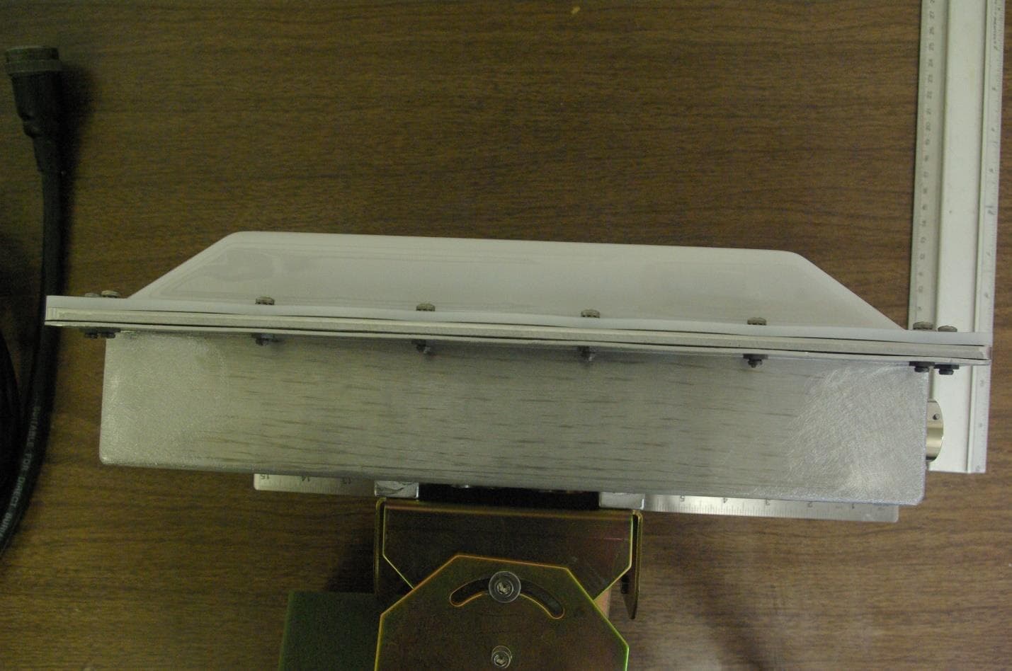
FIHE4SPT90V1
Oct 22, 2020Location and Monitoring Service Reader
Equipment Class
TNB - Licensed Non-Broadcast Station Transmitter