FIH051064SMobile transponder LMS Tag
TransCore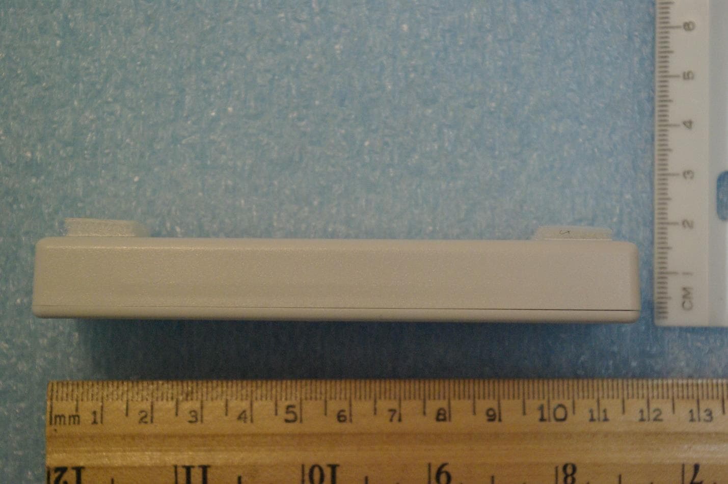
Click to zoom
Application Details
- Equipment Class
- LMS - Part 90 Location & Monitoring Transmitter
- Date of Grant
- Feb 09, 2020
- Application Purpose
- Original Equipment
- Date of Application
- Feb 09, 2020
- Equipment Note
- Mobile transponder LMS Tag
- Frequency Range
- 915.00000000 - 915.00000000
- Company
- TransCore
- Country
- United States
Documents & Files
Document Text
Text extracted from the exhibit documents filed with the FCC. Open a document above to read the original.
Users Manual
Trusted Transportation Solutions 16-6200-012 Rev X2 1/20 JED Installation Instructions TransCore’s JED is an IAG radio frequency identification (RFID) tag with integrated technology for easy user configuration. The JED can be configured with a 3-position switch, allowing users to manually select from 3 options. It is also available in a non-switchable case. A multi-color LED can be included in the case configuration when visual feedback is desired. General Installation Information Metallized Windshields: Some vehicle windshields contain a metallic treatment that could prevent an interior windshield-mounted tag from working correctly. If you have a vehicle with a metallized windshield, you may need to install an exterior tag on your vehicle instead of the interior windshield-mounted tag. Contact your local tag customer service center for more information. Metal-Free Zone: Some vehicles with metallized windshields have a metal-free zone, usually located near the rearview mirror. If your windshield has this zone, center the tag in that area and follow the installation instructions listed in these pages. Tinted Windshield: Some vehicles have a metallic tint across the top of the windshield that might interfere with reading the tag. If your windshield has this metallic tint, install the tag at least 2 inches (5.1 cm) below the tinted area. Nonmetallic tint does not affect tag performance. Metal Sun Visors: Some vehicles have an exterior-mounted sun visor that might interfere with reading the tag. If your vehicle has this visor, mount the tag at least 2 inches (5.1 cm) below the visor. Installation Instructions 2 Tag Installation and Removal Procedures The JED tag is designed for mounting to a vehicle’s interior windshield surface. It may be equipped with 3M™ Dual Lock™, hook-and-loop, or suction cups. Required Supplies • JED • Commercial glass cleaner and paper towels Installing the Tag Choose the location for your tag (Figure 1). The tag should be mounted approximately 1 inch (2.54 cm) below the rear view mirror post. Clean and dry the interior windshield surface completely before mounting the tag. The windshield temperature must be at least 68ºF (20ºC) for optimum bonding. Dual lock or hook-and-loop mounting strips 1. Peel the backing from the mounting strips to expose adhesive (Figure 2). Leave both sides of the strips pressed together to ensure the strips will align between the tag and the windshield. Apply the tag to the windshield using moderate pressure. Figure 1 Optimum Locations for Tag Performance TA0445 Figure 2 Peel backing from mounting strips to expose adhesive 3 JED Tag 2. Hold the tag so that the printed text or image is right side up and facing toward you ( Figure 3). Press the tag against the windshield and hold for 10 seconds. Note: When installing the tag using the mounting strips for the first time, leave the tag in place for at least 24 hours to allow the adhesive to cure. Suction cups 1. Hold the tag so that the printed text or image is right side up and facing toward you (Figure 3). 2. Moisten the cups and stick the tag to the windshield. 3. Press the tag against the windshield and hold for 10 seconds. Removing the Tag To remove a tag installed with mounting strips from the windshield, grip the tag at the top and bottom sides. Gently lift the tag away from the windshield on one end until the tag is free from the windshield. To remove a tag installed with suction cups, slide a finger under the tab on the suction cup to loosen it from the windshield surface. TA0444-002 Figure 3 Correct Tag Orientation Installation Instructions 4 NO UNAUTHORIZED MODIFICATIONS STATEMENT CAUTION: THIS EQUIPMENT MAY NOT BE MODIFIED, ALTERED, OR CHANGED IN ANY WAY WITHOUT PERMISSION. UNAUTHORIZED MODIFICATION MAY VOID THE EQUIPMENT AUTHORIZATION FROM THE FCC AND WILL VOID THE WARRANTY. AUCUNE MODIFICATION NON AUTORISÉE MISE EN GARDE : IL EST INTERDIT DE MODIFIER, D’ALTÉRER OU D’APPORTER DES CHANGEMENTS À CET APPAREIL DE QUELQUE MANIÈRE QUE CE SOIT SANS AUTORISATION. TOUTE MODIFICATION NON AUTORISÉE PEUT ANNULER L’AUTORISATION D’UTILISATION ACCORDÉE ET ANNULERA LA GARANTIE. RADIO FREQUENCY INTERFERENCE STATEMENTS This device complies with Part 15 of the FCC Rules. Operation is subject to the following two conditions: 1 ) This device may not cause interference, and 2 ) This device must accept any interference, including interference that may cause undesired operation of this device. RADIO FREQUENCY INTERFERENCE STATEMENTS This device complies with Industry Canada’s licence-exempt RSSs. Operation is subject to the following two conditions: 1 ) This device may not cause interference, and 2 ) This device must accept any interference, including interference that may cause undesired operation of this device. DÉCLARATION SUR LES INTERFÉRENCES DES FRÉQUENCES RADIO Le présent appareil est conforme aux CNR d’Industrie Canada applicables aux appareils radio exempts de licence. L’exploitation est autorisée aux deux conditions suivantes: 1 ) L’appareil ne doit pas produire de brouillage, et 2 ) L’utilisateur del’appareil doit accepter tout brouillage radioélectrique subi, même si le brouillage est susceptible d’en compromettre le fonctionnement. For more information: Sales Support 800.923.4824 Technical Support 505.856.8007 transcore.com Trusted Transportation Solutions © 2020 TransCore LP. All rights reserved. TRANSCORE is a registered trademark and is used under license. All other trademarks listed are the property of their respective owners. Contents subject to change. Printed in the U.S.A.
Cover Letter(s)
February 4, 2020 Timco Engineering Inc. 849 NW State Road 45 Newberry, FL 32669 Applicant: Transcore - Amtech Technology Center 8600 Jefferson Street NE Albuquerque, New Mexico 87113 Re: Confidentiality request for FCC ID: FIH051064S Dear Sirs: Transcore Amtech Technology Center requests that the material in the Block Diagram, Operational Description, Parts List, Schematics, and Tune Procedure be withheld from public disclosure pursuant to Sections 0.457 and 0.459 of the Commission’s Rules following grant of the application. In support of this request, Transcore Amtech Technology Center submits the following information. CONFIDENTIAL FILES Block Diagram 051064S Conf BlkDia.pdf Operational Description 051064S Conf OpDes.pdf Parts List 051064S Conf PartsList.pdf Schematics 051064S Conf Schem.pdf Tune Procedure 051064S Conf TunPro.pdf 1. Identification of the specific information for which confidential treatment is sought: The materials set forth in the Block Diagram, Operational Description, Parts List, Schematics, and Tune Procedure which are segregated, from the non-confidential exhibits of the application, are those for which confidentiality is sought. 2. Identification of the Commission proceeding in which the information was submitted or a description of the circumstances giving rise to the submission: The proceeding is that involving the application for equipment authorization (certification) under FCC ID No: FIH051064S 3. Explanation of the degree to which the information is commercial or financial, or contains a trade secret or is privileged: This material includes Block Diagram, Operational Description, Parts List, Schematics, and Tune Procedure. As such, this material is treated as highly confidential business information. ROGERS LABS, INC. 4405 West 259 th Terrace Louisburg, KS 66053 4. Explanation of the degree to which the information concerns a service that is subject to competition: The material for which confidentiality is sought is employed in the design and manufacture of this transmitting equipment that is offered on a highly competitive basis. Customers for this equipment have a variety of competing sources. 5. Explanation of how disclosure of the information could result in substantial competitive harm: Disclosure would, in effect, give away the fruits of the labors of Transcore Amtech Technology Center engineering personnel, who have designed the equipment and the manufacturing process. Disclosure would also offer competitors additional unwarranted insight into the state of the product development, thereby allowing competitors an advantage, not available to Transcore Amtech Technology Center. 6. Identification of any measures taken by the submitting party to prevent unauthorized disclosure: The information for which confidential treatment is sought is kept confidential by Transcore Amtech Technology Center and not made available to third parties except pursuant to non-disclosure agreements. 7. Identification of whether the information is available to the public and the extent of any previous disclosure of the information to third parties: To the knowledge of those preparing this application, the information has not been disclosed publicly heretofore. While the general theory of operation of this equipment has been the subject of numerous disclosures in industry and standards groups as well as in rule making proceedings of the FCC, the protection sought is narrowly drawn and pertains to certain specific implementations of this radio technology. 8. Justification of the period during which the submitting party asserts that the material should not be available for public disclosure: This material should not be disclosed for at least 25 years. While improvements in design are made relatively frequently, disclosure of the design information would lead to insights into both design and manufacturing techniques that could have an adverse competitive effect for many years to come. This equipment is designed for commercial, industrial, and governmental applications. As such, unlike most consumer equipment, this equipment could be used for more than a decade in some cases. As such, it is important that the design not be made available to unauthorized persons who might attempt to use knowledge of the design to compromise the applications for which the equipment will be employed. Should you require any further information, please contact the undersigned. Thank you for your consideration in this matter. Sincerely, Scot Rogers
External Photos
Rogers Labs, Inc. Transcore SN: 061003-03 Secure 4405 West 259 th Terrace Model: 051064S, Secure IAG Tag FCC ID: FIH051064S Louisburg, KS 66053 Test: 200117 IC: 1584A-FIH051064S Phone/Fax: (913) 837-3214 Test to: 47CFR Parts 2, 90 and RSS-137 Date: February 8, 2020 Revision 1 File: 051064S ExtPho Page 1 of 3 Equipment photographs Rogers Labs, Inc. Transcore SN: 061003-03 Secure 4405 West 259 th Terrace Model: 051064S, Secure IAG Tag FCC ID: FIH051064S Louisburg, KS 66053 Test: 200117 IC: 1584A-FIH051064S Phone/Fax: (913) 837-3214 Test to: 47CFR Parts 2, 90 and RSS-137 Date: February 8, 2020 Revision 1 File: 051064S ExtPho Page 2 of 3 Rogers Labs, Inc. Transcore SN: 061003-03 Secure 4405 West 259 th Terrace Model: 051064S, Secure IAG Tag FCC ID: FIH051064S Louisburg, KS 66053 Test: 200117 IC: 1584A-FIH051064S Phone/Fax: (913) 837-3214 Test to: 47CFR Parts 2, 90 and RSS-137 Date: February 8, 2020 Revision 1 File: 051064S ExtPho Page 3 of 3
ID Label/Location Info
Rogers Labs, Inc. Transcore SN: 061003-03 Secure 4405 West 259 th Terrace Model: 051064S, Secure IAG Tag FCC ID: FIH051064S Louisburg, KS 66053 Test: 200117 IC: 1584A-FIH051064S Phone/Fax: (913) 837-3214 Test to: 47CFR Parts 2, 90 and RSS-137 Date: February 8, 2020 Revision 1 File: 051064S LabelSmpl Page 1 of 1 Label Sample and Placement Label Sample placed on back of device
Internal Photos
Rogers Labs, Inc. Transcore SN: 061003-03 Secure 4405 West 259 th Terrace Model: 051064S, Secure IAG Tag FCC ID: FIH051064S Louisburg, KS 66053 Test: 200117 IC: 1584A-FIH051064S Phone/Fax: (913) 837-3214 Test to: 47CFR Parts 2, 90 and RSS-137 Date: February 8, 2020 Revision 1 File: 051064S IntPho Page 1 of 1 Internal photographs Transmitter PCB Front Antenna Transmitter PCB Back
RF Exposure Info
Rogers Labs, Inc. Transcore SN: 061003-03 Secure 4405 West 259 th Terrace Model: 051064S, Secure IAG Tag FCC ID: FIH051064S Louisburg, KS 66053 Test: 200117 IC: 1584A-FIH051064S Phone/Fax: (913) 837-3214 Test to: 47CFR Parts 2, 90 and RSS-137 Date: February 8, 2020 Revision 1 File: 051064S RFExpemtion Page 1 of 1 Model: 051064S Test Number: 200117 MPE Calculator RF Exposure uses EIRP for calculation. EIRP is based on TX power added to the antenna gain in dBi. dBi = dB gain compared to an isotropic radiator. S = power density in mW/cm^2 Transmitter Output power (dBm) 0.00 Transmitter Output power (mW) 1.00 Transmitter maximum Output power operating at 100% (Watts) 0.001 Antenna Gain (dBi) 1 Output Power for 100% duty Cycle operation (Watts) 0.001 Antenna Gain (Numeric) 1.26 Tx Frequency (MHz) 915 Calcualtion power (Watts) 0.001 dBd + 2.17 = dBi dBi to dBd 2.2 Antenna Gain (dBd) -1.17 Cable Loss (dB) 0.0 Adjusted Power (dBm) 0.0 Antenna minus cable (dBi) 1.00 Calculated ERP (mw) 0.764 EIRP = Po(dBM) + Gain (dB) Calculated EIRP (mw) 1.259 Radiated (EIRP) dBm 1.000 ERP = EIRP - 2.17 dB Radiated (ERP) dBm -1.170 Occupational Limit f/300 mW/cm 2 Frequency (MHz) Occupational Limit (mW/cm 2 ) Public Limit (mW/cm 2 ) 30.5 W/m 2 30-300 1 0.2 General Public Limit 300-1,500 f/300 f/1500 f/1500 mW/cm 2 1,500-10,000 5 1 6.1 W/m 2 Occupational Limit 0.6455ƒ 0.5 W/m 2 24.3 W/m 2 Frequency (MHz) Occupational Limit (W/m 2 ) Public Limit (W/m 2 ) General Public Limit 100-6,000 0.6455ƒ 0.5 0.02619ƒ 0.6834 W/m 2 6,000-15,000 50 2.8 W/m 2 48-300 1.291 300-6,000 0.02619ƒ 0.6834 6,000-15,000 50 10 f = Transmit Frequecny (MHz) f (MHz) = 915 P T = Power Input to Antenna (mW) P T (mW) = 1.0000 Duty cycle (percentage of operation) % = 100 P A = Adjusted Power due to Duty cycle or Cable Loss (mW) P A (mW) = 1.00 G N = Numeric Gain of the Antenna GN (numeric) = 1.26 S 20 = Power Density of device at 20cm (mW/m 2 ) S 20 =(P A G N )/(4πR 20 ) 2 S 20 (mW/m 2 ) = 0.00 S 20 = Power Density of device at 20cm (W/m 2 ) S 20 =(P A G N )/(4πR 20 ) 2 S 20 (W/m 2 ) = 0.00 S L = Power Density Limit (W/m 2 ) S L (W/m 2 )= 2.767 R C = Minimum distance to the Radiating Element for Compliance (cm) R C =√ (P A G N /4π S L ) R C (cm) = 0.6 S C = Power Density of the device at the Compliance Distance R C (W/m 2 ) S C =(P A G N )/(4πR C ) 2 S C (W/m 2 ) = 2.77 R 20 = 20cm R20= 20 For Complaince with Canada General Population Limits, User Manual must indicate a minimum seperation distance of 0.6 cm Or in Meters for Complaince with Canada General Population Limits, a minimum seperation distance of 0.006 Meters FCC radio frequency radiation exposure limits per 1.1310 IC radio frequency radiation exposure limits per RSS-102 EIRP Power density (S) mW/cm 2 = ------- 4 p r^2 r (cm) EIRP (mW)
Test Report
Testing NVLAP Lab Code 200087-0 Rogers Labs, Inc. Transcore SN: 061003-03 Secure 4405 West 259 th Terrace Model: 051064S, Secure IAG Tag FCC ID: FIH051064S Louisburg, KS 66053 Test: 200117 IC: 1584A-FIH051064S Phone/Fax: (913) 837-3214 Test to: 47CFR Parts 2, 90 and RSS-137 Date: February 8, 2020 Revision 2 File: Transcore 051064S TstRpt 200117 r2 Page 1 of 31 Engineering Test Report for Grant of Certification of Application 47CFR Part 90 and Industry Canada RSS-137 Location and Monitoring Service Transmitter Model: 051064S 915 MHz FCC ID: FIH051064S IC: 1584A-FIH051064S Transcore Amtech Technology Center 8600 Jefferson Street, NE Albuquerque, NM 87113 FCC Designation: US5305 ISED Registration: 3041A-1 Test Report Number: 200117 Test Date: January17, 2020 Authorized Signatory: Scot D. Rogers This report shall not be reproduced except in full, without the written approval of the laboratory. This report must not be used by the client to claim product certification, approval, or endorsement by NVLAP, NIST, or any agency of the U.S. Government. ROGERS LABS, INC. 4405 West 259 th Terrace Louisburg, KS 66053 Phone / Fax (913) 837-3214 Testing NVLAP Lab Code 200087-0 Rogers Labs, Inc. Transcore SN: 061003-03 Secure 4405 West 259 th Terrace Model: 051064S, Secure IAG Tag FCC ID: FIH051064S Louisburg, KS 66053 Test: 200117 IC: 1584A-FIH051064S Phone/Fax: (913) 837-3214 Test to: 47CFR Parts 2, 90 and RSS-137 Date: February 8, 2020 Revision 2 File: Transcore 051064S TstRpt 200117 r2 Page 2 of 31 Tabl e of Cont ents Table of Contents TABLE OF CONTENTS .................................................................................................. 2 REVISION HISTORY ...................................................................................................... 4 EXECUTIVE SUMMARY ................................................................................................ 5 OPINION / INTERPRETATION OF RESULTS ............................................................... 5 EQUIPMENT UNDER TEST ........................................................................................... 5 Equipment Function and Configuration .............................................................................................................. 6 Equipment Configuration ...................................................................................................................................... 6 APPLICATION FOR CERTIFICATION ........................................................................... 7 APPLICABLE STANDARDS AND TEST PROCEDURES ............................................. 9 UNITS OF MEASUREMENTS ........................................................................................ 9 TEST SITE LOCATIONS .............................................................................................. 10 ENVIRONMENTAL CONDITIONS................................................................................ 10 LIST OF TEST EQUIPMENT ........................................................................................ 11 TRANSMITTER POWER OUTPUT .............................................................................. 12 Measurements Required ...................................................................................................................................... 12 Test Arrangement ................................................................................................................................................. 12 Table 1 Transmitter Power Results ..................................................................................................................... 13 Figure 1 Transmitter Output Across Frequency Band........................................................................................ 14 MODULATION CHARACTERISTICS ........................................................................... 15 Measurements Required ...................................................................................................................................... 15 Test Arrangement ................................................................................................................................................. 15 Results Modulation Characteristics .................................................................................................................... 15 Testing NVLAP Lab Code 200087-0 Rogers Labs, Inc. Transcore SN: 061003-03 Secure 4405 West 259 th Terrace Model: 051064S, Secure IAG Tag FCC ID: FIH051064S Louisburg, KS 66053 Test: 200117 IC: 1584A-FIH051064S Phone/Fax: (913) 837-3214 Test to: 47CFR Parts 2, 90 and RSS-137 Date: February 8, 2020 Revision 2 File: Transcore 051064S TstRpt 200117 r2 Page 3 of 31 OCCUPIED BANDWIDTH ............................................................................................ 16 Measurements Required ...................................................................................................................................... 16 Test Arrangement ................................................................................................................................................. 16 Table 2 Occupied Bandwidth Results ................................................................................................................. 16 Figure 2 Occupied Bandwidth ............................................................................................................................ 17 SPURIOUS EMISSIONS ............................................................................................... 18 Measurements Required ...................................................................................................................................... 18 Test Arrangement ................................................................................................................................................. 18 Table 3 Spurious Emissions Results ........…
Text truncated - open the document above for the full version.
Test Setup Photos
Rogers Labs, Inc. Transcore SN: 061003-03 Secure 4405 West 259 th Terrace Model: 051064S, Secure IAG Tag FCC ID: FIH051064S Louisburg, KS 66053 Test: 200117 IC: 1584A-FIH051064S Phone/Fax: (913) 837-3214 Test to: 47CFR Parts 2, 90 and RSS-137 Date: February 8, 2020 Revision 1 File: 051064S TSup Page 1 of 3 Test setup photographs Rogers Labs, Inc. Transcore SN: 061003-03 Secure 4405 West 259 th Terrace Model: 051064S, Secure IAG Tag FCC ID: FIH051064S Louisburg, KS 66053 Test: 200117 IC: 1584A-FIH051064S Phone/Fax: (913) 837-3214 Test to: 47CFR Parts 2, 90 and RSS-137 Date: February 8, 2020 Revision 1 File: 051064S TSup Page 2 of 3 Rogers Labs, Inc. Transcore SN: 061003-03 Secure 4405 West 259 th Terrace Model: 051064S, Secure IAG Tag FCC ID: FIH051064S Louisburg, KS 66053 Test: 200117 IC: 1584A-FIH051064S Phone/Fax: (913) 837-3214 Test to: 47CFR Parts 2, 90 and RSS-137 Date: February 8, 2020 Revision 1 File: 051064S TSup Page 3 of 3
Contact Information
Applicant
Dale Scott(VP of Engineering and Manufacturing)
Test Firm
Rogers Labs, Inc.Scot Rogers
Technical Specifications
| # | Rule Parts | Frequency Range | Power Output | Emission | Tolerance |
|---|---|---|---|---|---|
| 1 | 90.353 | 915 MHz - 915 MHz | 1.00 mW | 7M50L1D | 2.5000000000 ppm |
Other Applications from TransCore
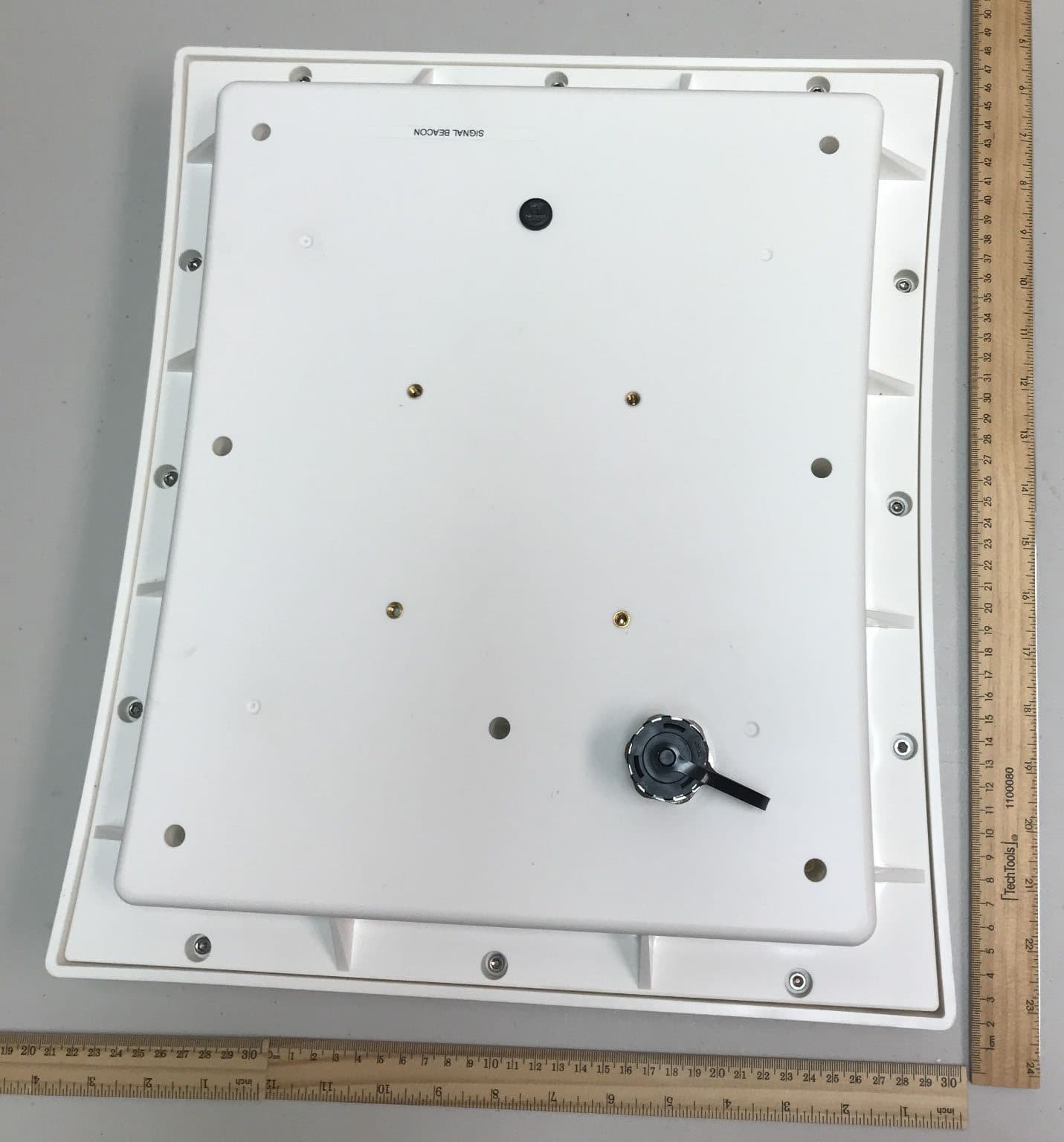
FIHSPSBPT15V1
Aug 27, 2026Low Power Communication Device for use in Toll exchange applications
Equipment Class
DTS - Digital Transmission System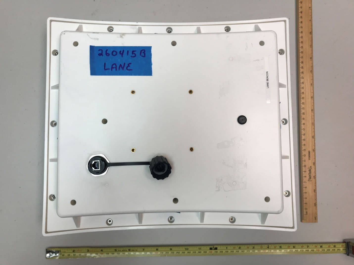
FIHSPLBPT15V1
Aug 26, 2026Low Power Communication Device for use in Toll exchange applications
Equipment Class
DTS - Digital Transmission System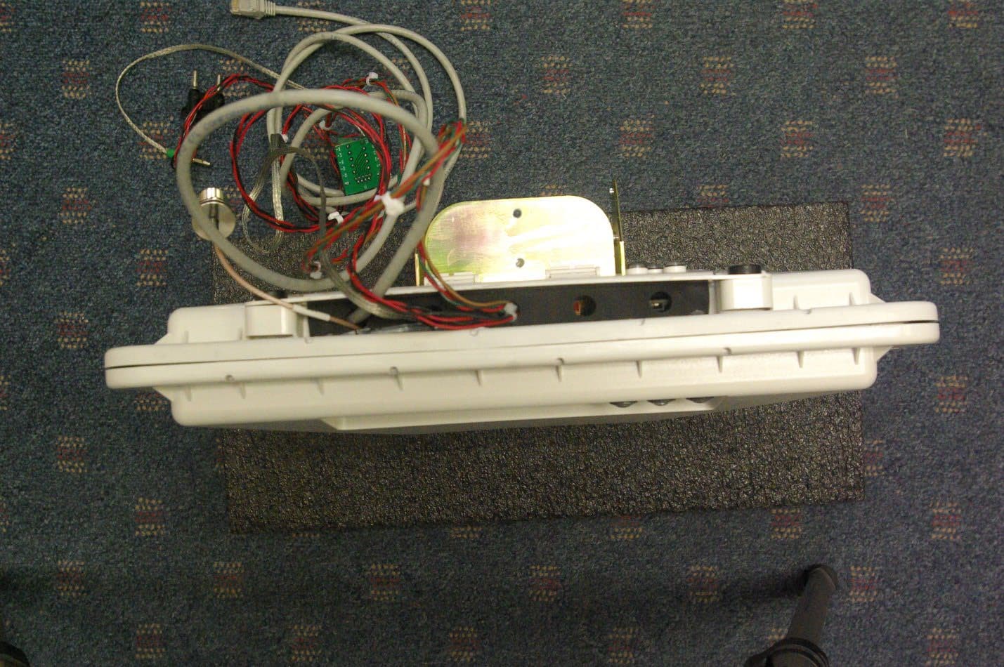
FIHE4FPT90V1
Sep 04, 2023Location and Monitoring Service Interrogator
Equipment Class
TNB - Licensed Non-Broadcast Station Transmitter
FIHE6PT90V2
Jan 24, 2023Location and Monitoring Service Interrogator
Equipment Class
TNB - Licensed Non-Broadcast Station TransmitterFIHE4SPT90V5
Jun 02, 2022Location and Monitoring Service Interrogator
Equipment Class
TNB - Licensed Non-Broadcast Station Transmitter