FIH05443LOW POWER TRANSMITTER (915 MHz)
TransCore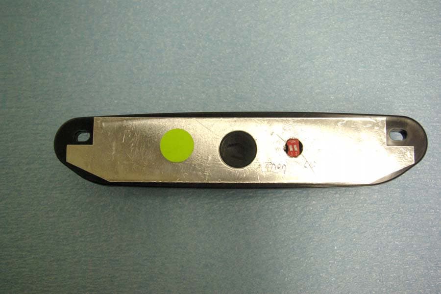
Click to zoom
Application Details
- Equipment Class
- DXX - Part 15 Low Power Communication Device Transmitter
- Date of Grant
- Aug 07, 2011
- Application Purpose
- Original Equipment
- Date of Application
- Aug 07, 2011
- Equipment Note
- LOW POWER TRANSMITTER (915 MHz)
- Frequency Range
- 915.00000000 - 915.00000000
- Company
- TransCore
- Country
- United States
Documents & Files
Document Text
Text extracted from the exhibit documents filed with the FCC. Open a document above to read the original.
Users Manual
This document describes the procedures to install the Exterior On-Board Unit (OBU) on the outside of a commercial or passenger vehicle. The typical mounting location for an Exterior OBU is over the license plate at the upper part of a vehicle’s front license plate area (Figure 1). Note: If your state does not require a front license plate, install the Exterior OBU in the area where the license plate would normally be mounted. If your vehicle does not have a designated front license plate mounting area, contact your tag agency for other options. Supplies •Exterior OBU (may have double-sided tape for secure mount) •Screwdriver (flat-blade or Phillips depending on your vehicle’s license plate mounting screws) •Optional two self-tapping threaded screws (customer supplied) •Optional TransCore Exterior Tag Accessory Kit (19077-01). This kit contains tamper-resistant mounting screws and wrench. Exterior OBU Installation Procedures To mount the Exterior OBU in the license plate area 1.Remove the screws from the license plate area of your front bumper (Figure 1). If your vehicle does not have mounting screws you will need two self-tapping threaded screws. You can also contact the tag agency to inquire about the optional TransCore Exterior Tag Accessory Kit. Note: You may need to use longer screws to fasten the OBU over the top area of your license plate. Figure 1 Typical Mounting Location for Exterior OBU Exterior On-Board Unit Installation 600039-003 08/11 www.transcore.com © 2010 TC License, Ltd. All rights reserved. TRANSCORE is a registered trademark of TC License, Ltd. All other trademarks listed are the property of their respective owners. Contents are subject to change. Printed in the U.S.A. SPECIFICATIONS 600039-003 08/11 2.Position the OBU so that it is within 18 inches (46 cm) of the center of the front bumper as shown by the shaded area in Figure 1. If your vehicle’s license plate mounting area is more than 18 inches (46 cm) from the center, you may need to select an alternate location on the bumper to mount the OBU. Contact your tag agency if your vehicle requires an alternate mounting location for the OBU. 3.Hold the OBU so that the mounting holes are to the top and fasten the OBU to the bumper using the license plate mounting screws (Figure 2). Install the OBU over the top area of the vehicle’s license plate if your vehicle has a front license plate. If your state does not require a front license plate, install the OBU in the area where a license plate would normally be mounted . Figure 2 Placement Over the Upper Area of the License Plate The license plate should have a 90-degree field-of-view to the overhead antenna as the vehicle approaches the toll plaza/gantry. If the vehicle bumper limits the field-of-view or if the license plate area is angled downward toward the pavement, you can use an angled mounting bracket to point the OBU upward to increase the field of view and improve performance (Figure 3). Figure 3 Examples of OBU Installations NO UNAUTHORIZED MODIFICATIONS STATEMENT Caution: This equipment may not be modified, altered, or changed in any way without permission from TransCore, LP. Unauthorized modification may void the equipment authorization from the FCC and will void the TransCore warranty. RADIO FREQUENCY INTERFERENCE STATEMENT S Note : This device complies with Part 15 of the FCC Rules and the Industry Canada Licence-Exempt RSS Standards. Operation is subject to the following two conditions: (1) this device may not cause interference, and (2) this device must accept any interference, including interference that may cause undesired operation of this device. Note: Le présent appareil est conforme aux CNR d’Industrie Canada applicables aux appareils radio exempts de licence. L’exploitation est autorisée aux deux conditions suivantes: (1) l’appareil ne doit pas produire de brouillage, et (2) l’utilisateur del’appareil doit accepter tout brouillage radioélectrique subi, même si le brouillage est susceptible d’en compromettre le fonctionnement.
Cover Letter(s)
August 5, 2011 Timco Engineering Inc. Federal Communications Commission 849 NW State Road 45 Equipment Approval Services Newberry, FL 32669 Pittsburgh, PA 15251-3315 Applicant: Transcore - Amtech Technology Center 8600 Jefferson Street NE Albuquerque, New Mexico 87113 Equipment: FCC ID: FIH05443 FCC Rule: Part 2 and 15.249 Modular transmitter certification Sirs The form 731 and application have been electronically submitted and any attachments will be up loaded to your site for use in obtaining grant of certification. Confidentiality is requested as outlined below. Short-term Pursuant to DA 04-1705 of the Commission’s public notice, we request short-term confidential treatment for the following information until 45 days after the Grant Date of Equipment Authorization in order to ensure sensitive business information remains confidential until the actual marketing of the device: External Photographs Short Term Conf ExtPho 05443.pdf Test Setup Short Term Conf TSup 05443.pdf User Manual Short Term Conf UserMan 05443.pdf Internal Photographs Short Term Conf IntPho 05443.pdf Permanent Transcore Amtech Technology Center requests that the material in the Parts List, Schematics, block diagram, and Operational Description be withheld from public disclosure in accordance with Section 0.459 of the Commission’s Rules, CFR47 0.459, following grant of the application. It is requested that the information contained in the operational description, block diagram, parts list, internal photographs, and schematics of the application be held confidential per Section 0.459. A statement of confidentiality will be attached with the application at the time of submittal. Block Diagram Conf BlkDia 05443.pdf Operational Description Conf OpDes 05443.pdf Schematics Conf Schem 05443.pdf Should you require any further information, please contact the undersigned. Thank you for your consideration in this matter. Sincerely, Scot Rogers Rogers Labs, Inc. Enclosures ROGERS LABS, INC. 4405 West 259 th Terrace Louisburg, KS 66053 Telephone / Facsimile (913) 837-3214
Cover Letter(s)
August 5, 2011 Timco Engineering Inc. 849 NW State Road 45 Newberry, FL 32669 Applicant: Transcore - Amtech Technology Center 8600 Jefferson Street NE Albuquerque, New Mexico 87113 Re: Confidentiality for submittal information regarding FCC ID number FIH05443 Product: Low Power Transmitter operating under part 15.249 Dear Sirs: Transcore Amtech Technology Center requests that the material in the Schematics, Operational Description, and Block Diagram be withheld from public disclosure in accordance with Section 0.459 of the Commission’s Rules, 47 C.F.R. 0.459, following grant of the application. In support of this request, Transcore Amtech Technology Center submits the following: CONFIDENTIAL FILES Block Diagram Conf BlkDia 05443.pdf Operational Description Conf OpDes 05443add.pdf Schematics Conf Schem 05443digital.pdf 1. Identification of the specific information for which confidential treatment is sought: The materials set forth in the Operational Description, block diagram, parts list, and Schematics, which are segregated, from the non-confidential exhibits of the application, are those for which confidentiality is sought. 2. Identification of the Commission proceeding in which the information was submitted or a description of the circumstances giving rise to the submission: The proceeding is that involving the application for equipment authorization (certification) under FCC ID No: FIH05443 3. Explanation of the degree to which the information is commercial or financial, or contains a trade secret or is privileged: This material includes a detailed theory of operation, circuit diagrams, and schematic. As such, this material is treated as highly confidential business information. 4. Explanation of the degree to which the information concerns a service that is subject to competition: ROGERS LABS, INC. 4405 West 259 th Terrace Louisburg, KS 66053 The material for which confidentiality is sought is employed in the design and manufacture of this transmitting equipment that is offered on a highly competitive basis. Customers for this equipment have a variety of competing sources. 5. Explanation of how disclosure of the information could result in substantial competitive harm: Disclosure would, in effect, give away the fruits of the labors of Transcore Amtech Technology Center engineering personnel, who have designed the equipment and the manufacturing process. Disclosure would also offer competitors additional unwarranted insight into the state of the product development, thereby allowing competitors an advantage, not available to Transcore Amtech Technology Center. 6. Identification of any measures taken by the submitting party to prevent unauthorized disclosure: The information for which confidential treatment is sought is kept confidential by Transcore Amtech Technology Center and not made available to third parties except pursuant to non-disclosure agreements. 7. Identification of whether the information is available to the public and the extent of any previous disclosure of the information to third parties: To the knowledge of those preparing this application, the information has not been disclosed publicly heretofore. While the general theory of operation of this equipment has been the subject of numerous disclosures in industry and standards groups as well as in rule making proceedings of the FCC, the protection sought is narrowly drawn and pertains to certain specific implementations of this radio technology. 8. Justification of the period during which the submitting party asserts that the material should not be available for public disclosure: This material should not be disclosed for at least 25 years. While improvements in design are made relatively frequently, disclosure of the design information would lead to insights into both design and manufacturing techniques that could have an adverse competitive effect for many years to come. This equipment is designed for commercial, industrial, and governmental applications. As such, unlike most consumer equipment, this equipment could be used for more than a decade in some cases. As such, it is important that the design not be made available to unauthorized persons who might attempt to use knowledge of the design to compromise the applications for which the equipment will be employed. Should you require any further information, please contact the undersigned. Thank you for your consideration in this matter. Sincerely, Scot Rogers
Cover Letter(s)
August 5, 2011 Office of Engineering and Technology Federal Communications Commission Columbia, MD 21046 Applicant: Transcore Amtech Technology Center 8600 Jefferson Street NE Albuquerque, New Mexico 87113 Re: Short-term Confidentiality request for submittal information regarding FCC ID number FIH05443 Product: Low Power Transmitter operating under part 15.249 Dear Sirs: Transcore Amtech Technology Center requests that the following information be withheld from public disclosure until 45 days after the Grant of Equipment Authorization in accordance with DA-04-1705 of the Commission’s public notice. Short term confidential files External Photographs Short Term Conf ExtPho 05443.pdf Test Setup Short Term Conf TSup 05443.pdf User Manual Short Term Conf UserMan 05443.pdf Internal Photographs Short Term Conf IntPho 05443.pdf Permanent Confidential files Block Diagram Conf BlkDia 05443.pdf Operational Description Conf OpDes 05443.pdf Schematics Conf Schem 05443.pdf Should you require any further information, please contact the undersigned. Thank you for your consideration in this matter. Sincerely, Scot Rogers ROGERS LABS, INC. 4405 West 259 th Terrace Louisburg, KS 66053
External Photos
Rogers Labs, Inc. Transcore Amtech Technology Center 4405 W. 259th Terrace Model: 05443 IC: 1584A-05443 Louisburg, KS 66053 Test #: 110712 FCC ID#: FIH05443 Phone/Fax: (913) 837-3214 Test to: FCC Parts 2, 15C Page 1 of 1 Revision 1 file: Short Term Conf ExtPho 05443 Date: 8/5/2011 Equipment photographs
ID Label/Location Info
Rogers Labs, Inc. Transcore Amtech Technology Center 4405 W. 259th Terrace Model: 05443 IC: 1584A-05443 Louisburg, KS 66053 Test #: 110712 FCC ID#: FIH05443 Phone/Fax: (913) 837-3214 Test to: FCC Parts 2, 15C Page 1 of 1 Revision 1 file: LabelSmp 05443 Date: 8/5/2011 ID Label sample and Placement
Internal Photos
Rogers Labs, Inc. Transcore Amtech Technology Center 4405 W. 259th Terrace Model: 05443 IC: 1584A-05443 Louisburg, KS 66053 Test #: 110712 FCC ID#: FIH05443 Phone/Fax: (913) 837-3214 Test to: FCC Parts 2, 15C Page 1 of 1 Revision 1 file: Short Term Conf IntPho 05443 Date: 8/5/2011 Internal photographs
Parts List/Tune Up Info
1 Introduction The 05443 transmitter referred to herein is part of a multi-protocol Radio-Frequency Identification (RFID) transponder. The transmitter is battery-powered, microprocessor- controlled and communicates in the Inter-Agency Group (IAG) protocol. 2 Tune-Up Instructions The 05443 transmitter is manufactured with fixed components and no means for tuning are provided. Transmitters are 100% tested to ensure compliance.
Test Report
NVLAP Lab Code 200087-0 Rogers Labs, Inc. Transcore Amtech Technology Center FCC ID#: FIH05443 4405 W. 259th Terrace Model: 05443 IC: 1584A-05443 Louisburg, KS 66053 Test #: 110712 SN: ENG1 Phone/Fax: (913) 837-3214 Test to: FCC 15c (15.245), IC RSS-210 Page 1 of 23 Revision 1 File: Transcore 05443 TstRpt Date: August 5, 2011 SUBMITTAL APPLICATION REPORT FOR GRANT OF CERTIFICATION FOR Model: 05443 915 MHz Low Power Transmitter FCC ID: FIH05443 IC: 1584A-05443 FOR TRANSCORE AMTECH TECHNOLOGY CENTER 8600 Jefferson Street, NE Albuquerque, NM 87113 Test Report Number: 110712 Authorized Signatory: Scot D. Rogers NVLAP Lab Code 200087-0 Rogers Labs, Inc. Transcore Amtech Technology Center FCC ID#: FIH05443 4405 W. 259th Terrace Model: 05443 IC: 1584A-05443 Louisburg, KS 66053 Test #: 110712 SN: ENG1 Phone/Fax: (913) 837-3214 Test to: FCC 15c (15.245), IC RSS-210 Page 2 of 23 Revision 1 File: Transcore 05443 TstRpt Date: August 5, 2011 Engineering Test Report For Application Of Grant of Certification FOR CFR47, PART 15C - Intentional Radiators Paragraph 15.249 And Industry Canada RSS-210 Low Power Transmitter For TRANSCORE Amtech Technology Center 8600 Jefferson Street, NE Albuquerque, NM 87113 Model: 05443 Frequency 915.0 MHz FCC ID: FIH05443 IC: 1584A-05443 Test Date: July 12, 2011 Certifying Engineer: Scot D. Rogers Rogers Labs, Inc. 4405 West 259 th Terrace Louisburg, KS 66053 Telephone / Facsimile: (913) 837-3214 This report shall not be reproduced except in full, without the written approval of the laboratory. This report must not be used by the client to claim product endorsement by NVLAP, NIST, or any agency of the U.S. Government. ROGERS LABS, INC. 4405 West 259 th Terrace Louisburg, KS 66053 Phone / Fax (913) 837-3214 NVLAP Lab Code 200087-0 Rogers Labs, Inc. Transcore Amtech Technology Center FCC ID#: FIH05443 4405 W. 259th Terrace Model: 05443 IC: 1584A-05443 Louisburg, KS 66053 Test #: 110712 SN: ENG1 Phone/Fax: (913) 837-3214 Test to: FCC 15c (15.245), IC RSS-210 Page 3 of 23 Revision 1 File: Transcore 05443 TstRpt Date: August 5, 2011 Table of Contents TABLE OF CONTENTS .................................................................................................. 3 FORWARD ..................................................................................................................... 4 OPINION / INTERPRETATION OF RESULTS ............................................................... 4 ENVIRONMENTAL CONDITIONS.................................................................................. 4 APPLICATION FOR CERTIFICATION ........................................................................... 5 APPLICABLE STANDARDS & TEST PROCEDURES .................................................. 6 EQUIPMENT TESTED .................................................................................................... 6 EQUIPMENT FUNCTION AND TESTING PROCEDURES ............................................ 6 EQUIPMENT AND CABLE CONFIGURATIONS ........................................................... 6 AC Line Conducted Emission Test Procedure .................................................................................................. 6 Radiated Emission Test Procedure ..................................................................................................................... 7 UNITS OF MEASUREMENTS ........................................................................................ 7 TEST SITE LOCATIONS ................................................................................................ 7 LIST OF TEST EQUIPMENT .......................................................................................... 8 INTENTIONAL RADIATORS .......................................................................................... 9 Antenna Requirements ........................................................................................................................................ 9 Restricted Bands of Operation ............................................................................................................................ 9 Data Radiated Emissions in Restricted Bands ..................................................................................................... 9 Summary of Results for Radiated Emissions in Restricted Bands .................................................................... 10 Radiated Emissions Limits; General Requirements ....................................................................................... 10 Figure One Plot of Radiated Emissions Taken in screen room ......................................................................... 11 Figure Two Plot of Radiated Emissions Taken in screen room ......................................................................... 11 Figure Three Plot of Radiated Emissions Taken in screen room ....................................................................... 12 Figure Four Plot of Radiated Emissions Taken in screen room ......................................................................... 12 Figure Five Plot of Radiated Emissions Taken in screen room ......................................................................... 13 Data General Radiated Emissions from EUT .................................................................................................... 13 Summary of Results for General Radiated Emissions ....................................................................................... 13 Operation in the Band 902 – 928 MHz ............................................................................................................. 14 Figure Six Plot of in Frequency Band Emissions .............................................................................................. 15 Figure Seven Plot of Occupied Bandwidth ........................................................................................................ 15 Data Transmitter Radiated Emissi…
Text truncated - open the document above for the full version.
Test Setup Photos
Rogers Labs, Inc. Transcore Amtech Technology Center 4405 W. 259th Terrace Model: 05443 IC: 1584A-05443 Louisburg, KS 66053 Test #: 110712 FCC ID#: FIH05443 Phone/Fax: (913) 837-3214 Test to: FCC Parts 2, 15C Page 1 of 1 Revision 1 file: Short Term Conf TSup 05443 Date: 8/5/2011 Test setup photographs (note EUT is placed on metal “licenses” plate, as this configuration is representative of operational use)
Contact Information
Applicant
Dale Scott(VP of Engineering and Manufacturing)
Test Firm
Rogers Labs, Inc.Scot Rogers
Technical Specifications
| # | Rule Parts | Frequency Range | Power Output |
|---|---|---|---|
| 1 | 15C | 915 MHz - 915 MHz | - |
Other Applications from TransCore
FIHSPSBPT15V1
Aug 27, 2026Low Power Communication Device for use in Toll exchange applications
Equipment Class
DTS - Digital Transmission System
FIHSPLBPT15V1
Aug 26, 2026Low Power Communication Device for use in Toll exchange applications
Equipment Class
DTS - Digital Transmission System
FIHE4FPT90V1
Sep 04, 2023Location and Monitoring Service Interrogator
Equipment Class
TNB - Licensed Non-Broadcast Station Transmitter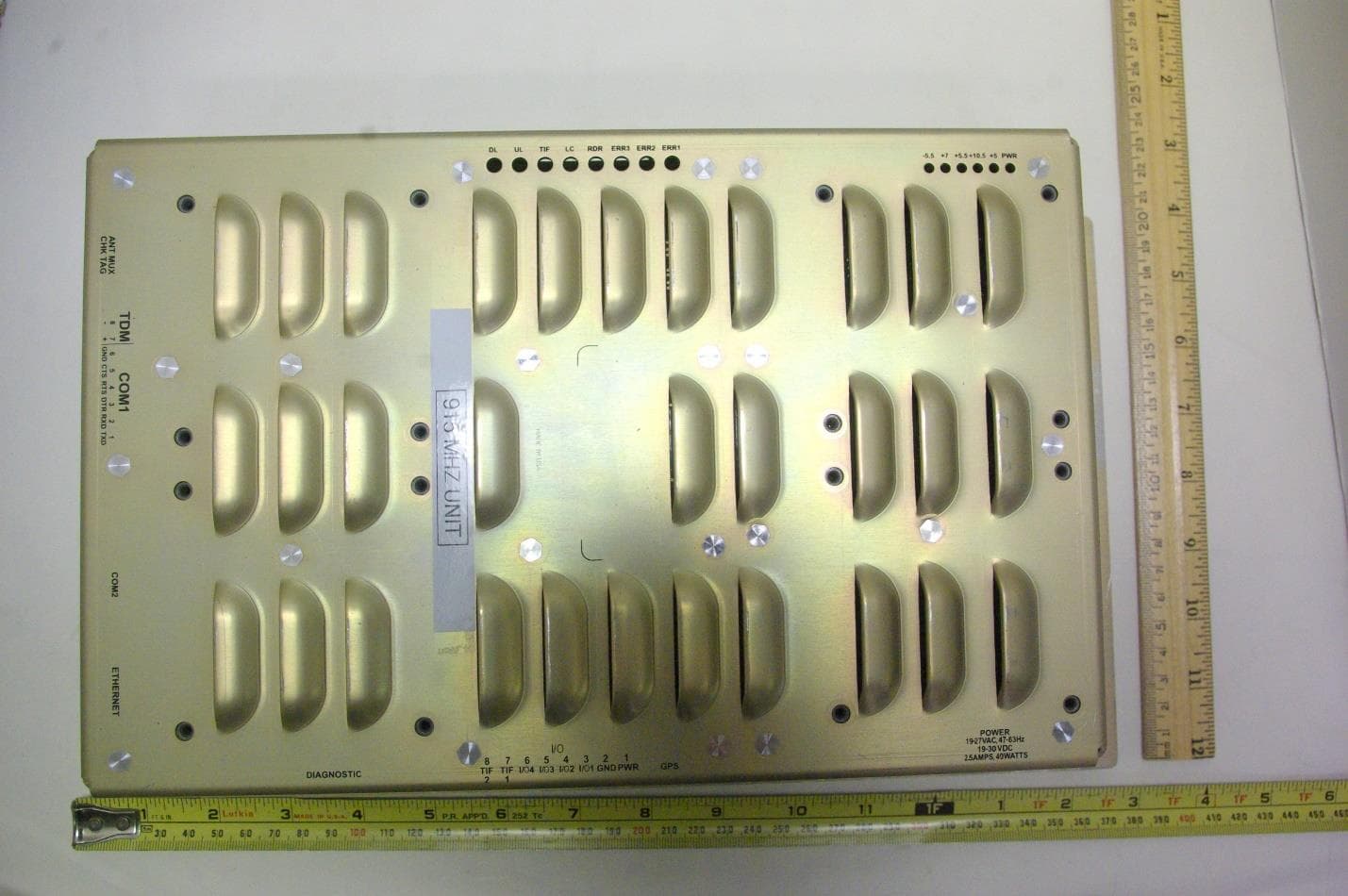
FIHE6PT90V2
Jan 24, 2023Location and Monitoring Service Interrogator
Equipment Class
TNB - Licensed Non-Broadcast Station TransmitterFIHE4SPT90V5
Jun 02, 2022Location and Monitoring Service Interrogator
Equipment Class
TNB - Licensed Non-Broadcast Station Transmitter