FIH05726LOW POWER TRANSCEIVER MODULE
TransCore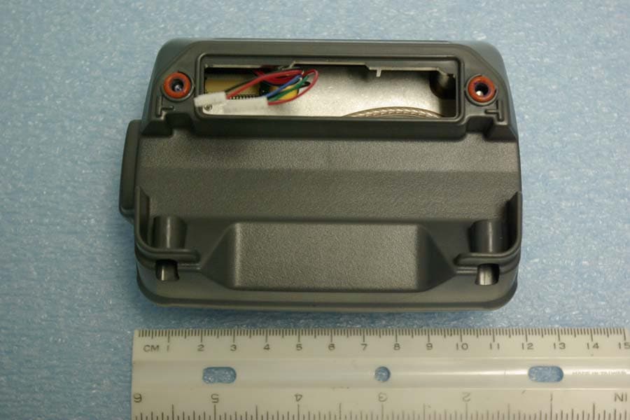
Click to zoom
Application Details
- Equipment Class
- DXT - Part 15 Low Power Transceiver, Rx Verified
- Date of Grant
- Dec 14, 2010
- Application Purpose
- Original Equipment
- Date of Application
- Dec 14, 2010
- Equipment Note
- LOW POWER TRANSCEIVER MODULE
- Frequency Range
- 915.00000000 - 915.00000000
- Company
- TransCore
- Country
- United States
Documents & Files
Document Text
Text extracted from the exhibit documents filed with the FCC. Open a document above to read the original.
Users Manual
05726 IAG Read-Only Radio Module Developer’s Guide TransCore, Inc. 8600 Jefferson Street NE Albuquerque, New Mexico 87113 December 2010 P/N 412114 ©2010 TC License, Ltd. All rights reserved. TRANSCORE and ENCOMPASS are registered trademarks of TC License. All other trademarks listed are the property of their respective owners. Contents are subject to change. Printed in the U.S.A. For further information, contact: TransCore 3410 Midcourt Road, Suite 102 Carrollton, Texas 75006 USA Phone: (214) 461-4031 Fax: (214) 461-6478 Technical Support Web: transcore.com/rfidsupport NO UNAUTHORIZED MODIFICATIONS CAUTION: TRANSCORE IS NOT RESPONSIBLE FOR ANY RADIO OR TV INTERFERENCE CAUSED BY UNAUTHORIZED MODIFICATIONS TO THIS EQUIPMENT. SUCH MODIFICATIONS COULD VOID THE USER’S AUTHORITY TO OPERATE THE EQUIPMENT. Contents Hardware Overview ........................................................................................................ 1 RF Connector .............................................................................................................. 1 Digital Connector ........................................................................................................... 2 Firmware Overview ........................................................................................................ 2 Regional Support ........................................................................................................... 3 Frequency ....................................................................................................................... 3 Host-to-Reader Communication ................................................................................... 4 Reader -to-Host Communication .................................................................................. 5 CCITT CRC-16 Calculation ......................................................................................... 6 Antenna Connector ........................................................................................................ 8 Communications Connector ......................................................................................... 8 Connectors ..................................................................................................................... 9 List of Figures Figure 1. Host-to-Reader Communication Packets .......................................................................... 4 Figure 2. Host-to-Reader Communication Packets .......................................................................... 5 Figure 3. 05726 Radio Module Communications Interfaces ............................................................ 8 List of Tables Table 1. Features of the 05726 Radio Module ................................................................................. 1 Table 2. Digital Connector Pin Assignments .................................................................................... 2 Table 3. Host-to-Reader Communication Descriptions .................................................................... 5 Table 4. Reader-to-Host Communication Descriptions .................................................................... 5 Table 5. Proposed Host-to-Reader Format of IAG Read (follows ThingMagic requirements) ......... 7 Table 6. Proposed Reader-to-Host Format of IAG Read Response ................................................ 7 iii Introduction to the 05726 IAG Read-Only Radio Module The 05726 embedded IAG read-only module is a radio frequency identification (RFID) radio that can be integrated into other systems to create RFID-enabled products that support the E-ZPass ® Interagency Group (IAG) protocol. This document is written for developers and explains how to incorporate the 05726 TransCore Radio Module (hereafter called the 05726 radio module) into a third-party host system. Hardware Overview The 05726 radio module is a single board module designed for more space- constrained applications. The digital and analog electronics are located on the same circuit board. The 05726 radio module is designed to be incorporated into products requiring capabilities in a small form factor. Table 1 shows the basic features of the radio hardware. Table 1. Features of the 05726 Radio Module Specification Value Input Power Requirements +5V DC Communication Interfaces High-speed serial interface Protocols supported IAG read-only Dimensions (L x D x H) 3.1 x 2.5 x 0.3 in. (78 x 63 x 8 mm) RF Connector The 05726 radio module supports one MMCX connector for a single monostatic antenna. 1 05726 IAG Read-Only Radio Module Developer’s Guide Digital Connector The digital connector provides power and serial communications signals. The connector is a 14-pin digital connector. Table 2 lists the pin-outs and descriptions. Table 2. Digital Connector Pin Assignments Pin No. Description 1 GND 2 GND 3 GND 4 +5V 5 +5V 6 NO CONNECTION 7 NO CONNECTION 8 NO CONNECTION 9 NO CONNECTION 10 NO CONNECTION 11 RS-232 RX TTL from host 12 RS-232 RX TTL to host 13 NO CONNECTION 14 NO CONNECTION Firmware Overview The software for the 05726 radio module is loaded at the factory and cannot be updated in the field. If the software requires updating, the radio module has to be returned to the factory. 2 05726 IAG Read-Only Radio Module Developer’s Guide Functionality of the Embedded Module Regional Support This radio module has been designed to comply with the following regulatory requirements: North America Region FCC 47 CFG Chapter 1, Part 15 Industrie Canada RSS-210 Frequency The 05726 radio module has been designed to operate at a fixed frequency of 915.00 MHz. 3 05726 IAG Read-Only Radio Module Developer’s Guide Overview of the Communication Protocol The serial communication between a host and the reader is based on a synchronized command-response/master-slave mechanism. Whenever the host sends a message to the reader, it cannot send another message until after it receives a response. The reader never initiates…
Text truncated - open the document above for the full version.
Cover Letter(s)
December 13, 2010 Timco Engineering Inc. 849 NW State Road 45 Newberry, FL 32669 Applicant: Transcore - Amtech Technology Center 8600 Jefferson Street NE Albuquerque, New Mexico 87113 Re: Confidentiality for submittal information regarding FCC ID number FIH05726 Product: Transmitter module operating under part 15.249 Dear Sirs: Transcore Amtech Technology Center requests that the material in the Schematics, Operational Description, Block Diagram, and parts list be withheld from public disclosure in accordance with Section 0.459 of the Commission’s Rules, 47 C.F.R. 0.459, following grant of the application. In support of this request, Transcore Amtech Technology Center submits the following: CONFIDENTIAL FILES Block Diagram Conf BlkDia 05726.pdf Operational Description Conf OpDes 05726.pdf Schematics Conf Schem 05726.pdf 1. Identification of the specific information for which confidential treatment is sought: The materials set forth in the Operational Description, block diagram, parts list, and Schematics, which are segregated, from the non-confidential exhibits of the application, are those for which confidentiality is sought. 2. Identification of the Commission proceeding in which the information was submitted or a description of the circumstances giving rise to the submission: The proceeding is that involving the application for equipment authorization (certification) under FCC ID No: FIH05726 3. Explanation of the degree to which the information is commercial or financial, or contains a trade secret or is privileged: This material includes a detailed theory of operation, circuit diagrams, and schematic. As such, this material is treated as highly confidential business information. ROGERS LABS, INC. 4405 West 259 th Terrace Louisburg, KS 66053 4. Explanation of the degree to which the information concerns a service that is subject to competition: The material for which confidentiality is sought is employed in the design and manufacture of this transmitting equipment that is offered on a highly competitive basis. Customers for this equipment have a variety of competing sources. 5. Explanation of how disclosure of the information could result in substantial competitive harm: Disclosure would, in effect, give away the fruits of the labors of Transcore Amtech Technology Center engineering personnel, who have designed the equipment and the manufacturing process. Disclosure would also offer competitors additional unwarranted insight into the state of the product development, thereby allowing competitors an advantage, not available to Transcore Amtech Technology Center. 6. Identification of any measures taken by the submitting party to prevent unauthorized disclosure: The information for which confidential treatment is sought is kept confidential by Transcore Amtech Technology Center and not made available to third parties except pursuant to non-disclosure agreements. 7. Identification of whether the information is available to the public and the extent of any previous disclosure of the information to third parties: To the knowledge of those preparing this application, the information has not been disclosed publicly heretofore. While the general theory of operation of this equipment has been the subject of numerous disclosures in industry and standards groups as well as in rule making proceedings of the FCC, the protection sought is narrowly drawn and pertains to certain specific implementations of this radio technology. 8. Justification of the period during which the submitting party asserts that the material should not be available for public disclosure: This material should not be disclosed for at least 25 years. While improvements in design are made relatively frequently, disclosure of the design information would lead to insights into both design and manufacturing techniques that could have an adverse competitive effect for many years to come. This equipment is designed for commercial, industrial, and governmental applications. As such, unlike most consumer equipment, this equipment could be used for more than a decade in some cases. As such, it is important that the design not be made available to unauthorized persons who might attempt to use knowledge of the design to compromise the applications for which the equipment will be employed. Should you require any further information, please contact the undersigned. Thank you for your consideration in this matter. Sincerely, Scot Rogers
Cover Letter(s)
Date: Wednesday, December 08, 2010 Federal Communications Commission Industry Canada Equipment Approval Services Head, Equipment Approval Unit P.O. Box 35815 Department of Communications Pittsburgh, PA 15251-3315 1241 Clyde Avenue Ottawa, Ontario K2C 1Y3 Applicant: TransCore 8600 Jefferson St NE Albuquerque, New Mexico 87113 Equipment: 05726 FCC ID: FIH05726 IC: 1584A-05726 Rules: CFR47 Part 2 and 15.212, 15.249 (Modular Transmitter), and Industry Canada RSS-210 Re: Modular transmitter approval Gentlemen As required in CFR47 15.212 and Industry Canada RSS-GEN regarding unlicensed modular transmitter approval, the following information has been addressed. The transmitter module is a complete RF transmitter containing its own reference oscillator, antenna etc. The connections available on the module are for power and data interface only. Below please find information, addressing each requirement from RSS-GEN and CFR47 15.212. Per RSS-GEN (a) The module is a complete radio transmitter with its own reference oscillator, antenna, etc. The only connectors to the module are power supply and modulation/data inputs. (b) The module has its own RF shielding. (c) The module utilizes buffered modulation/data input(s) to ensure that the module will comply with RSS- 210 requirements under conditions of excessive data rates or over-modulation. (d) The module has its own power supply regulation. This is to ensure that the module will comply with RSS-210 requirements regardless of the design of the power supplying circuitry in the host device, which houses the module. (e) The certification submission contains a detailed description of the configuration of all antennas that will be used with the module. Per CFR 47 15.212 (i) The radioelements of the modular transmitter have their own shielding. (ii) The modular transmitter utilizes buffered modulation/data inputs to ensure that the module will comply with part 15 requirements under conditions of excessive data rates or over- modulation. (iii) The modular transmitter utilizes power supply regulation. (iv) The modular transmitter utilizes a unique antenna connection (MMCX) and complies with the antenna connection requirements of 15.203. (v) The module was tested in a stand-alone configuration utilizing a test fixture for interface allowing for testing. The module complies with part 15 emissions limits regardless of the device into which it is eventually installed. (vi) The module has the FCC ID number permanently affixed to the equipment and information supplied to the end OEM regarding label placement on the outside of the device into which the module is contained. (vii) The unit complies with CFR47 regulations as stated in the user manual. Adequate instructions are supplied with the unit to explain the requirements. (viii) The unit complies with the RF exposure requirements as stated in 2.1091, 2.1093, and part 15. Sincerely Scot D. Rogers
Cover Letter(s)
December 13, 2010 Timco Engineering Inc. Federal Communications Commission 849 NW State Road 45 Equipment Approval Services Newberry, FL 32669 Pittsburgh, PA 15251-3315 Applicant: Transcore - Amtech Technology Center 8600 Jefferson Street NE Albuquerque, New Mexico 87113 Equipment: FCC ID: FIH05726 FCC Rule: Part 2 and 15.249 Modular transmitter certification Sirs The form 731 and application have been electronically submitted and any attachments will be up loaded to your site for use in obtaining grant of certification. Confidentiality is requested as outlined below. Permanent Transcore Amtech Technology Center requests that the material in the Parts List, Schematics, block diagram, and Operational Description be withheld from public disclosure in accordance with Section 0.459 of the Commission’s Rules, CFR47 0.459, following grant of the application. It is requested that the information contained in the operational description, block diagram, parts list, internal photographs, and schematics of the application be held confidential per Section 0.459. A statement of confidentiality will be attached with the application at the time of submittal. Block Diagram Conf BlkDia 05726.pdf Operational Description Conf OpDes 05726.pdf Schematics Conf Schem 05726.pdf Should you require any further information, please contact the undersigned. Thank you for your consideration in this matter. Sincerely, Scot Rogers Rogers Labs, Inc. Enclosures ROGERS LABS, INC. 4405 West 259 th Terrace Louisburg, KS 66053 Telephone / Facsimile (913) 837-3214
External Photos
Rogers Labs, Inc. Transcore Amtech Technology Center FCC ID: FIH05726 4405 W. 259th Terrace Model: 05726 IC: 1584A-05726 Louisburg, KS 66053 Test #: 101123 SN: E1 Phone/Fax: (913) 837-3214 Test to: FCC Parts 2, 15.249 and RSS-210 Date: 12/13/2010 Revision 1 File: ExtPho 05726 Page 1 of 2 Equipment photographs Transceiver Module Rogers Labs, Inc. Transcore Amtech Technology Center FCC ID: FIH05726 4405 W. 259th Terrace Model: 05726 IC: 1584A-05726 Louisburg, KS 66053 Test #: 101123 SN: E1 Phone/Fax: (913) 837-3214 Test to: FCC Parts 2, 15.249 and RSS-210 Date: 12/13/2010 Revision 1 File: ExtPho 05726 Page 2 of 2 Transceiver Module and Support Device
ID Label/Location Info
Rogers Labs, Inc. Transcore Amtech Technology Center FCC ID: FIH05726 4405 W. 259th Terrace Model: 05726 IC: 1584A-05726 Louisburg, KS 66053 Test #: 101123 SN: E1 Phone/Fax: (913) 837-3214 Test to: FCC Parts 2, 15.249 and RSS-210 Date: 12/13/2010 Revision 1 File: LabelSmp 05726 Page 1 of 1 Label Sample and Placement FCC ID Label Placement on module as shown 1584A-05726 FIH05726 05726
Internal Photos
Rogers Labs, Inc. Transcore Amtech Technology Center FCC ID: FIH05726 4405 W. 259th Terrace Model: 05726 IC: 1584A-05726 Louisburg, KS 66053 Test #: 101123 SN: E1 Phone/Fax: (913) 837-3214 Test to: FCC Parts 2, 15.249 and RSS-210 Date: 12/13/2010 Revision 1 File: IntPho 05726 Page 1 of 3 Internal photographs Transceiver module removed from enclosure attached to antenna Transceiver module placement in enclosure attached to antenna Rogers Labs, Inc. Transcore Amtech Technology Center FCC ID: FIH05726 4405 W. 259th Terrace Model: 05726 IC: 1584A-05726 Louisburg, KS 66053 Test #: 101123 SN: E1 Phone/Fax: (913) 837-3214 Test to: FCC Parts 2, 15.249 and RSS-210 Date: 12/13/2010 Revision 1 File: IntPho 05726 Page 2 of 3 Transceiver PCB Rogers Labs, Inc. Transcore Amtech Technology Center FCC ID: FIH05726 4405 W. 259th Terrace Model: 05726 IC: 1584A-05726 Louisburg, KS 66053 Test #: 101123 SN: E1 Phone/Fax: (913) 837-3214 Test to: FCC Parts 2, 15.249 and RSS-210 Date: 12/13/2010 Revision 1 File: IntPho 05726 Page 3 of 3 Authorized Antenna and module
Parts List/Tune Up Info
Thursday, December 09, 2010 Page 1 of 1 IAG Read Only Radio Tune-up Procedure The IAG Radio is factory calibrated manually for a peak power of 15.00dBm. For peak power measurement, the radio is fixed to transmit a 20uSec Pulse at a fixed frequency of 915.00 MHz. This output signal is measured with a spectrum analyzer in zero span operation (Agilent Model no. E4440A, or equivalent). The power is the adjusted by adjusting the bias resistor to the PA to 15 dBm +/- 0.5 dB. 8600 Jefferson St NE Albuquerque, New Mexico 87113 505-856-8000 tel 505-857-0716 fax
RF Exposure Info
Rogers Labs, Inc. Transcore Amtech Technology Center FCC ID: FIH05726 4405 W. 259th Terrace Model: 05726 IC: 1584A-05726 Louisburg, KS 66053 Test #: 101123 SN: E1 Phone/Fax: (913) 837-3214 Test to: FCC Parts 2, 15.249 and RSS-210 Date: 12/13/2010 Revision 1 File: RFExp 05726 Page 1 of 1
Test Report
NVLAP Lab Code 200087-0 Rogers Labs, Inc. Transcore - Amtech Technology Center 4405 West 259 th Terrace Model: 05726 SN: E1 FCC ID#: FIH05726 Louisburg, KS 66053 Test #:101123 IC: 1584A-05726 Phone/Fax: (913) 837-3214 Test to: FCC Parts 2 and 15.249, RSS-210 Date: December 13, 2010 Revision 1 File: Transcore 05726 TstRpt 101123 Page 1 of 35 APPLICATION SUBMITTAL REPORT FOR FCC And INDUSTRY CANADA GRANT OF CERTIFICATION FOR Model: 05726 915 MHz Transmitter Module FCC ID: FIH05726 IC: 1584A-05726 FOR TRANSCORE - AMTECH TECHNOLOGY CENTER 8600 Jefferson Street, NE Albuquerque, NM 87113 Test Report Number: 101123 Authorized Signatory: Scot D. Rogers NVLAP Lab Code 200087-0 Rogers Labs, Inc. Transcore - Amtech Technology Center 4405 West 259 th Terrace Model: 05726 SN: E1 FCC ID#: FIH05726 Louisburg, KS 66053 Test #:101123 IC: 1584A-05726 Phone/Fax: (913) 837-3214 Test to: FCC Parts 2 and 15.249, RSS-210 Date: December 13, 2010 Revision 1 File: Transcore 05726 TstRpt 101123 Page 2 of 35 Engineering Test Report For Grant Of Certification Application Submittal Per CFR47, Part 15C - Intentional Radiators Paragraph 15.249 and Industry Canada, RSS-210 Low Power Transmitter For TRANSCORE - AMTECH TECHNOLOGY CENTER 8600 Jefferson Street, NE Albuquerque, NM 87113 Larry Barnsdale Senior Quality Engineer III Model: 05726 915 MHz Transmitter Module FCC ID#: FIH05726, IC: 1584A-05726 Test Date: November 23, 2010 Certifying Engineer: Scot D. Rogers Rogers Labs, Inc. 4405 West 259 th Terrace Louisburg, KS 66053 Phone: (913) 837-3214 Facsimile: (913) 837-3214 This report shall not be reproduced except in full, without the written approval of the laboratory. This report must not be used by the client to claim product endorsement by NVLAP, NIST, or any agency of the U.S. Government. ROGERS LABS, INC. 4405 West 259 th Terrace Louisburg, KS 66053 Phone / Fax (913) 837-3214 NVLAP Lab Code 200087-0 Rogers Labs, Inc. Transcore - Amtech Technology Center 4405 West 259 th Terrace Model: 05726 SN: E1 FCC ID#: FIH05726 Louisburg, KS 66053 Test #:101123 IC: 1584A-05726 Phone/Fax: (913) 837-3214 Test to: FCC Parts 2 and 15.249, RSS-210 Date: December 13, 2010 Revision 1 File: Transcore 05726 TstRpt 101123 Page 3 of 35 Table of Contents TABLE OF CONTENTS .................................................................................................. 3 FORWARD ..................................................................................................................... 5 OPINION / INTERPRETATION OF RESULTS ............................................................... 5 ENVIRONMENTAL CONDITIONS.................................................................................. 5 APPLICATION FOR CERTIFICATION ........................................................................... 6 APPLICABLE STANDARDS .......................................................................................... 7 EQUIPMENT TESTED .................................................................................................... 7 EQUIPMENT FUNCTION ............................................................................................... 7 EQUIPMENT CONFIGURATION .................................................................................... 8 UNITS OF MEASUREMENTS AND TEST PROCEDURES ........................................... 8 AC Line Conducted Emission Test Procedure .................................................................................................. 8 Figure One Test Arrangement for AC Line Conducted Emissions (Table Top Equipment) ............................... 9 Radiated Emission Test Procedure ................................................................................................................... 10 Figure Two Test Arrangement for Radiated Emissions ..................................................................................... 10 TEST SITE LOCATIONS .............................................................................................. 11 LIST OF TEST EQUIPMENT ........................................................................................ 11 GENERAL EMISSIONS (UNINTENTIONAL RADIATORS) ......................................... 12 AC Line Conducted EMI ................................................................................................................................... 12 Figure Three AC Line Conducted Emissions Line 1 ......................................................................................... 13 Figure Four AC Line Conducted Emissions Line 2 ........................................................................................... 13 AC Line Conducted Emissions Data ................................................................................................................. 14 Summary of Results for AC Line Conducted Emissions ................................................................................ 14 Radiated EMI ..................................................................................................................................................... 15 Figure Five Plot of General Radiated Emissions ............................................................................................... 16 Figure Six Plot of General Radiated Emissions ................................................................................................. 16 Figure Seven Plot of General Radiated Emissions ............................................................................................ 17 Figure Eight Plot of General Radiated Emissions ............................................................................................. 17 NVLAP Lab Code 200087-0 Rogers Labs, Inc. Transcore - Amtech Technology Center 4405 West 259 th Terrace Model: 05726 SN: E1 FCC ID#: FIH05726 Louisburg, KS 66053 Test #:101123 IC: 1584A-05726 Phone/Fax: (913) 837-3214 Test to: FCC Parts 2 and 15.249, RSS-210 Date: December 13, 2010 Revision 1 Fi…
Text truncated - open the document above for the full version.
Test Setup Photos
Rogers Labs, Inc. Transcore Amtech Technology Center FCC ID: FIH05726 4405 W. 259th Terrace Model: 05726 IC: 1584A-05726 Louisburg, KS 66053 Test #: 101123 SN: E1 Phone/Fax: (913) 837-3214 Test to: FCC Parts 2, 15.249 and RSS-210 Date: 12/13/2010 Revision 1 File: TSup 05726 Page 1 of 3 Test setup photographs (Module separated from support equipment) Module with plastic enclosure Rogers Labs, Inc. Transcore Amtech Technology Center FCC ID: FIH05726 4405 W. 259th Terrace Model: 05726 IC: 1584A-05726 Louisburg, KS 66053 Test #: 101123 SN: E1 Phone/Fax: (913) 837-3214 Test to: FCC Parts 2, 15.249 and RSS-210 Date: 12/13/2010 Revision 1 File: TSup 05726 Page 2 of 3 Equipment placed on OATS during testing Rogers Labs, Inc. Transcore Amtech Technology Center FCC ID: FIH05726 4405 W. 259th Terrace Model: 05726 IC: 1584A-05726 Louisburg, KS 66053 Test #: 101123 SN: E1 Phone/Fax: (913) 837-3214 Test to: FCC Parts 2, 15.249 and RSS-210 Date: 12/13/2010 Revision 1 File: TSup 05726 Page 3 of 3 AC Line Conducted emissions test setup
Contact Information
Applicant
Dale Scott(VP of Engineering and Manufacturing)
Test Firm
Rogers Labs, Inc.Scot Rogers
Technical Specifications
| # | Rule Parts | Frequency Range | Power Output |
|---|---|---|---|
| 1 | 15C | 915 MHz - 915 MHz | - |
Other Applications from TransCore
FIHSPSBPT15V1
Aug 27, 2026Low Power Communication Device for use in Toll exchange applications
Equipment Class
DTS - Digital Transmission System
FIHSPLBPT15V1
Aug 26, 2026Low Power Communication Device for use in Toll exchange applications
Equipment Class
DTS - Digital Transmission System
FIHE4FPT90V1
Sep 04, 2023Location and Monitoring Service Interrogator
Equipment Class
TNB - Licensed Non-Broadcast Station Transmitter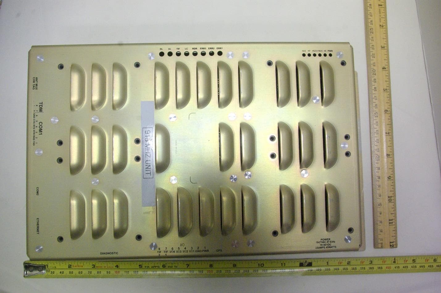
FIHE6PT90V2
Jan 24, 2023Location and Monitoring Service Interrogator
Equipment Class
TNB - Licensed Non-Broadcast Station TransmitterFIHE4SPT90V5
Jun 02, 2022Location and Monitoring Service Interrogator
Equipment Class
TNB - Licensed Non-Broadcast Station Transmitter