FKGTKI400ABGSG2212.1� Tablet PC
Twinhead International CorporationApplication Details
- Equipment Class
- NII - Unlicensed National Information Infrastructure TX
- Date of Grant
- Apr 18, 2007
- Application Purpose
- Original Equipment
- Date of Application
- Apr 18, 2007
- Equipment Note
- 12.1� Tablet PC
- Frequency Range
- 5180.00000000 - 5320.00000000
- Country
- Taiwan
Documents & Files
Document Text
Text extracted from the exhibit documents filed with the FCC. Open a document above to read the original.
Users Manual
User’sGuide SaharaSlatePC®i400Series TabletPC Chapter00:Prefacei Rea ding this manual will help yo u get the mostout of your new Sahara SlatePC. If you are a new computeruser, or just new to Ta blet PCs, you shouldread thro ugh the manualcarefullybefore first usingyou r new SaharaSlate PC. Visit us onlineat ww w.tabletkiosk.co m for additionalres ources and informati on to help yo u get the mostfromyour SaharaSlat e PC i400 Se ri es Ta blet PC. Co pyr ight ©2007 SandDuneVe ntures, Inc . All Rights Reserved. All product infor mat ion is subjectto changewithoutnotice.SaharaSlat e PC is a re gist ered trad emarkand TabletKioskis a trademarkof Sand Dune Ventures, Inc.inthe UnitedStates and/orothercountries. Microsoft, Windows XP, Window s Vistaand the Windows logo are either re gistered trad emarksor trademarksof Microsoft Co rporation in the United Stat es and/or othercountries.Intel , Co re , Centrino Duo, Celeron, Co re Duo Insidelogo,Celeron Insi de logo and CentrinoDuo Insid e logo are trademarksor regi ste red trademarks of In tel Corporationin the UnitedStates and/or otherc ountries. The Blueto oth® wordmarkand logos are owned by the BluetoothSIG, Inc . and any use of such marksby Ta bletKioskis under license.Linuxis a registered trademarkof Linus Torvalds. Chapter00 Pr eface iiChapter00:Preface Disclaimer Th e specificat ions and information in this manualare subjectto change without prior notice in order to improvereliability, design and/orfunction, but this does not representa commitment on the part of the manufacturer.The manufacturer assumes no responsibilityfo r error s or omissionsin this document. In no event will the manufacturer be liablefor direct,indirect, special, incident al, or co nsequentialdamagesarisingout of the use, or inability to use, the Tablet PC or this documentation, even if advised of the possibility of such damages. Th is document containsproprietaryinformation protected by cop yright. All ri ghts are res erved.No part of this manualmay be rep rod ucedby any mechanical,electronic,or othermeansin any formwithoutprior writtenpermission of TabletKiosk. If yo u have any questions regardingthe Sahara Slat e PC, or the infor mat ion cont ained withinthis manual,pleasecontact Ta bletKioskat [email protected] m. Saf ety Instructions For your safety and that of yo ur equipment,pleasefollowthese rules for handlingand care of your SaharaSlate PC. Keepthis User ’s Manual handy for later referenceby you and otherusers. Neve r use spra ys, liquidsor cleaningdetergentsfor cleaningthe Sahara SlatePC Tablet. Us e a microfiber clothfor cleaningthe tou ch scre en. Avoi d the use of tissue papersincethe tissue fibers can easilylodge between the touch screenand the top coverof the tablet. Neve r pourliquids into any openingsor directlyon the Sahara Slat e PC. Th is cou ld res ult in fire or electrical shock. Ensure the volta ge ra nge of the pow er outletis betw een 100V and 240V before connectingthe SaharaSlat e PC. Exceedingthe Chapter00:Prefaceiii maximum rate d voltagemay cause damage to the AC adapter or to the Sahara SlatePC. This cou ld resu lt in fire or electricalshock. Wh en the AC adapter is plugged int o an electricaloutlet,place the power cor d so it will not be steppedor walkedon. Do not place objects over or on the power co rd. Use the Sahara SlatePC in a clean,dry , temperature controlled env ironment. Do not use the SaharaSlate PC in areasof high humidity , aroundwat er or outdoors whileit is raining. Neve r openor disassemblethe Sahara Slat e PC. For safet y rea sons,and to pre ve nt permanent damage, the equipment should only be repa ire d by qualified service personnel. Co nt act a qualified serv ice cen ter if any of the following issues should arise: 1.the AC adapter,powerco rd or plug is damaged 2.liquid has beenspilled into the SaharaSlate PC 3.the Sahara SlatePC has been exposedto excessivemoisture 4.the Sahara SlatePC exhibitserro rs and/ordoesnot function according to specifications 5.the Sahara SlatePC has been dro ppedor otherwise physic ally damaged Lithium bat te ri es can be dangerou s. Thereis a danger of explosionif the battery is inco rrectlyreplaced.Replaceonly with the sameor equiva lent type reco mmendedby the manufacturer. Dispose of used batt eriesacco rdingto stat e or local hazardous wa ste requirement s. Under no circumstances should the user att emptto disassemble the power supply.The powersupply has no user-replaceable part s and its insides con tain co mponentsthat are electrically ivChapter00:Preface charged with hazardou s vo ltagelevelsthat can cause serio us personalinjury. A defectivepow er supply mustbe returnedto you r dealer. Saf ety Notices for the PowerCo rd Th is equipment has a 2 or 3-wirepowercord.Replacethe pow er cord if it becomesdamaged.Contact your dealerfor an exact rep lace ment. In the U. S.A. and Canada, the pow er cord mustbe a UL-listed detachablepow er cord (in Canada, CSA-certified). 2-wire cor dSPT- 2 18AWG 3-wire cor dSVT or SJT, 18 AWG , 3-conductor Th e cord should be prov ided with a molded-oncord connector body at the other end. The cord lengthmustnot exceed3 meters. Outside the U.S.A . and Canada, the plug mustbe ra ted fo r 250 VAC, 2.5 amp minimum,and must display an int ernational agency approva l mark ing. The cord mustbe suitablefor use in the end-user’s country.Cons ult you r dealeror the local electrical authorities if you are unsure of the type of powercord to use in you r count ry. Volt age changesoccur automaticallyin the power supply. Notice of FCC Compliance a. Fe deralCommunicationsCo mmission(FCC) Requirements, Part 15: This equipment has beentested and foundto comply with the limits for a Class B digitaldevice, pursuantto Part 15 of the FCC Rules. Thes e limitsare designedto prov ide re asonablepro tectionagainst harmful interfer ence in a res idential installation.This equipment Chapter00:Prefacev generat es, uses, and can radia te rad io frequencyenergy and if not installed and use…
Text truncated - open the document above for the full version.
External Photos
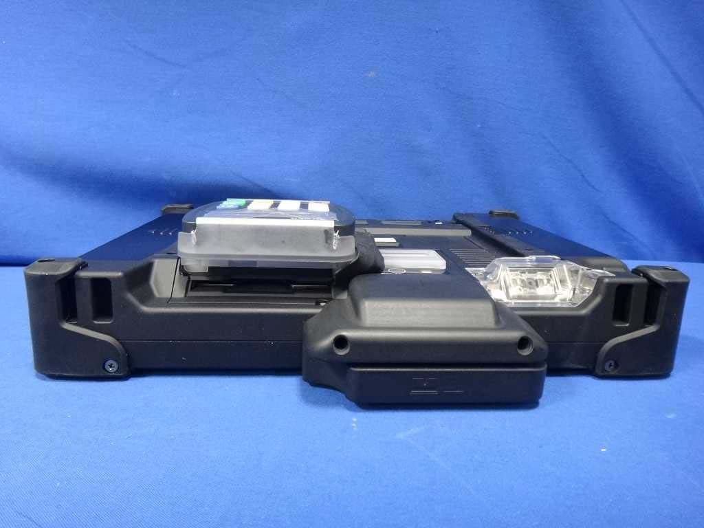
Page 1 CONSTRUCTION PHOTOS OF EUT Page 2 Page 32 Page 33 Page 34
ID Label/Location Info
FCC ID .: P4Q-2007VEN1001 Label Location
Internal Photos
Page 2 Page 3 Page 4 Page 5 Page 6 Page 7 Page 8 Page 9 Page 10 Page 11 Page 12 Page 13 Page 14 Page 15 Page 16 Page 17 Page 18 Page 19 Page 20 Page 21 Page 22 Page 23 Page 24 Page 25 Page 26 Page 27 Page 28 Page 29 Page 30 Page 31
Operational Description
FCC ID: FKGTKI400ABGSG22 Report No.: RF960123A03 Operational Description The transmitter of the EUT (12.1" Tablet PC) is powered by AC adapter. The EUT (12.1" Tablet PC) includes two transmission functions which are WLAN and Bluetooth. This device is a 12.1" Tablet PC, which operates in both of the 5GHz and 2.4GHz bands and can’t transmitting simultaneously, the maximum data rate could be 54Mbps. WLAN Information: FCC 15.407(c) states: The device shall automatically discontinue transmission in case of either absence of information to transmit or operational failure. These provisions are not intended to preclude the transmission of control or signaling information or the use of repetitive codes used by certain digital technologies to complete frame or burst intervals. Applicants shall include in their application for equipment authorization a description of how this requirement is met” Data transmission is always initiated by software, which is then pass down through the MAC, through the digital and analog baseband, and finally to the RF chip. Several special packets (ACKs, CTS, PSPoll, etc...) are initiated by the MAC. There are the only ways the digital baseband portion will turn on the RF transmitter, which it then turns off at the end of the packet. Therefore, the transmitter will be on only while one of the aforementioned packets are being transmitted. FHSS Information: The transmitter of the EUT (12.1" Tablet PC) is powered by AC Adapter. This device is a Frequency Hopping device with 79 hopping frequencies. For more detailed instruction, please take a look at the user’s manual. Note: The bluetooth and WLAN functions can transmit simultaneously. For more detailed instruction, please take a look at the user’s manual.
RF Exposure Info
Report no.: SA960123A03 1 Report Format Version 2.0.5 SAR TEST REPORT REPORT NO.: SA960123A03 MODEL NO.: SG22 series (Refer to item 2.1 for the more details) RECEIVED: Jan. 24, 2007 TESTED: Mar. 23 ~ Mar. 26, 2007 ISSUED: Apr. 12, 2007 APPLICANT: TWINHEAD INTERNATIONAL CORP. ADDRESS: 10F, No. 550, Rueiguang Rd., Neihu Chiu, Taipei, Taiwan 114, R.O.C. ISSUED BY: Advance Data Technology Corporation LAB ADDRESS: No. 47, 14 th Ling, Chia Pau Tsuen, Lin Kou Hsiang 244, Taipei Hsien, Taiwan, R.O.C. TEST LOCATION: No. 19, Hwa Ya 2 nd Rd., Wen Hwa Tsuen, Kwei Shan Hsiang, Taoyuan Hsien 333, Taiwan, R.O.C. This test report consists of 44 pages in total except Appendix. It may be duplicated completely for legal use with the approval of the applicant. It should not be reproduced except in full, without the written approval of our laboratory. The client should not use it to claim product endorsement by CNLA, A2LA or any government agencies. The test results in the report only apply to the tested sample. Report no.: SA960123A03 2 Report Format Version 2.0.5 TABLE OF CONTENTS 1. CERTIFICATION .........................................................................................................3 2. GENERAL INFORMATION..........................................................................................4 2.1 GENERAL DESCRIPTION OF EUT............................................................................4 2.2 GENERAL DESCRIPTION OF APPLIED STANDARDS .............................................5 2.3 GENERAL INOFRMATION OF THE SAR SYSTEM ...................................................6 2.4 GENERAL DESCRIPTION OF THE SPATIAL PEAK SAR EVALUATION ..................9 3. DESCRIPTION OF SUPPORT UNITS ......................................................................12 4. DESCRIPTION OF TEST MODES AND CONFIGURATIONS ..................................13 4.1. DESCRIPTION OF ANTENNA LOCATION ...............................................................13 4.2. DESCRIPTION OF ASSESSMENT POSITION ........................................................14 4.3. DESCRIPTION OF TEST MODE ..............................................................................15 4.4. SUMMARY OF TEST RESULTS ...............................................................................16 5. TEST RESULTS ........................................................................................................17 5.1 TEST PROCEDURES ...............................................................................................17 5.2 MEASURED SAR RESULTS ....................................................................................19 5.3 SAR LIMITS...............................................................................................................23 5.4 RECIPES FOR TISSUE SIMULATING LIQUIDS ......................................................24 5.5 TEST EQUIPMENT FOR TISSUE PROPERTY ........................................................29 6. SYSTEM VALIDATION ..............................................................................................30 6.1 TEST EQUIPMENT ...................................................................................................30 6.2 TEST PROCEDURE .................................................................................................31 6.3 VALIDATION RESULTS ............................................................................................33 6.4 SYSTEM VALIDATION UNCERTAINTIES ................................................................34 6.1 SYSTEM VALIDATION UNCERTAINTIES (FOR 5.0GHz) ........................................35 7. MEASUREMENT SAR PROCEDURE UNCERTAINTIES.........................................36 7.1. PROBE CALIBRATION UNCERTAINTY...................................................................36 7.2. ISOTROPY UNCERTAINTY .....................................................................................37 7.3. BOUNDARY EFFECT UNCERTAINTY.....................................................................37 7.4. PROBE LINEARITY UNCERTAINTY ........................................................................38 7.5. READOUT ELECTRONICS UNCERTAINTY ............................................................38 7.6. RESPONSE TIME UNCERTAINTY ..........................................................................38 7.7. INTEGRATION TIME UNCERTAINTY......................................................................39 7.8. PROBE POSITIONER MECHANICAL TOLERANCE ...............................................40 7.9. PROBE POSITIONING .............................................................................................40 7.10. PHANTOM UNCERTAINTY ......................................................................................41 7.11. DASY4 UNCERTAINTY BUDGET (FOR 2.4GHz) ....................................................42 7.12. DASY4 UNCERTAINTY BUDGET (FOR 5 ~ 6GHz) .................................................43 8. INFORMATION ON THE TESTING LABORATORIES ..............................................44 APPENDIX A: TEST CONFIGURATIONS AND TEST DATA APPENDIX B: ADT SAR MEASUREMENT SYSTEM APPENDIX C: PHOTOGRAPHS OF SYSTEM VALIDATION APPENDIX D: SYSTEM CERTIFICATE & CALIBRATION Report no.: SA960123A03 3 Report Format Version 2.0.5 1. CERTIFICATION PRODUCT: 12.1" Tablet PC MODEL: SG22 series (Refer to item 2.1 for the more details) BRAND: Sahara (Refer to item 2.1 for the more details) APPLICANT: TWINHEAD INTERNATIONAL CORP. TESTED: Mar. 23 ~ Mar. 26, 2007 TEST SAMPLE: ENGINEERING SAMPLE STANDARDS: FCC Part 2 (Section 2.1093), RSS-102 FCC OET Bulletin 65, Supplement C (01-01) IEEE 1528-2003 The above equipment (Model: SG22 series) have been tested by Advance Data Technology Corporation, and found compliance with the requirement of the above standards. The test record, data evaluation & Equipment Under Test (EUT) configurations represented herein are true and accurate accounts of the measure…
Text truncated - open the document above for the full version.
RF Exposure Info
B - 1 APPENDIX B: ADT SAR MEASUREMENT SYSTEM C - 1 APPENDIX C: PHOTOGRAPHS OF SYSTEM VALIDATION APPENDIX D: SYSTEM CERTIFICATE & CALIBRATION D1: SAM PHANTOM D2: DOSIMETRIC E-FIELD PROBE D3: DAE D4: SYSTEM VALIDATION DIPOLE
RF Exposure Info
A - 1 APPENDIX A: TEST DATA Liquid Level Photo MSL 2450MHz D=152mm MSL 5800MHz D=150mm A - 2 Date/Time: 2007/3/23 10:27:46 Test Laboratory: Advance Data Technology Aux Ant-11b-Ch1-LCD Down-Mode 1 DUT: 12.1” Tablet PC ; Type: SG22 series ; Test Frequency: 2412 MHz Communication System: 802.11b ; Frequency: 2412 MHz ; Duty Cycle: 1:1 ; Modulation type: DBPSK Medium: MSL2450 Medium parameters used: f = 2412 MHz; σ = 1.88 mho/m; ε r = 53.4; ρ = 1000 kg/m 3 ; Liquid level : 152 mm Phantom section: Flat Section ; Separation distance : 0 mm (The bottom side of the EUT to the Phantom) Antenna type : Internal Antenna ; Air temp. : 22.1 degrees ; Liquid temp. : 21.2 degrees DASY4 Configuration: - Probe: ET3DV6 - SN1790 ; ConvF(4.35, 4.35, 4.35) ; Calibrated: 2006/11/23 - Sensor-Surface: 4mm (Mechanical Surface Detection) - Electronics: DAE3 Sn510 ; Calibrated: 2006/9/7 - Phantom: SAM 12 ; Type: SAM V4.0 ; Serial: TP 1202 - Measurement SW: DASY4, V4.7 Build 53 ; Postprocessing SW: SEMCAD, V1.8 Build 172 Low Channel 1/Area Scan (10x15x1): Measurement grid: dx=15mm, dy=15mm Maximum value of SAR (measured) = 0.101 mW/g Low Channel 1/Zoom Scan (7x7x7) (7x7x7)/Cube 0: Measurement grid: dx=5mm, dy=5mm, dz=5mm Reference Value = 2.75 V/m Peak SAR (extrapolated) = 0.204 W/kg SAR(1 g) = 0.094 mW/g; SAR(10 g) = 0.048 mW/g Maximum value of SAR (measured) = 0.102 mW/g A - 3 Date/Time: 2007/3/23 10:51:47 Test Laboratory: Advance Data Technology Aux Ant-11b-Ch6-LCD Down-Mode 1 DUT: 12.1” Tablet PC ; Type: SG22 series ; Test Frequency: 2437 MHz Communication System: 802.11b ; Frequency: 2437 MHz ; Duty Cycle: 1:1 ; Modulation type: DBPSK Medium: MSL2450 Medium parameters used: f = 2437 MHz; σ = 1.91 mho/m; ε r = 53.3; ρ = 1000 kg/m 3 ; Liquid level : 152 mm Phantom section: Flat Section ; Separation distance : 0 mm (The bottom side of the EUT to the Phantom) Antenna type : Internal Antenna ; Air temp. : 22.1 degrees ; Liquid temp. : 21.2 degrees DASY4 Configuration: - Probe: ET3DV6 - SN1790 ; ConvF(4.35, 4.35, 4.35) ; Calibrated: 2006/11/23 - Sensor-Surface: 4mm (Mechanical Surface Detection) - Electronics: DAE3 Sn510 ; Calibrated: 2006/9/7 - Phantom: SAM 12 ; Type: SAM V4.0 ; Serial: TP 1202 - Measurement SW: DASY4, V4.7 Build 53 ; Postprocessing SW: SEMCAD, V1.8 Build 172 Mid Channel 6/Area Scan (10x15x1): Measurement grid: dx=15mm, dy=15mm Maximum value of SAR (measured) = 0.093 mW/g Mid Channel 6/Zoom Scan (7x7x7) (7x7x7)/Cube 0: Measurement grid: dx=5mm, dy=5mm, dz=5mm Reference Value = 2.72 V/m Peak SAR (extrapolated) = 0.225 W/kg SAR(1 g) = 0.104 mW/g; SAR(10 g) = 0.053 mW/g Maximum value of SAR (measured) = 0.113 mW/g A - 4 Date/Time: 2007/3/23 11:14:28 Test Laboratory: Advance Data Technology Aux Ant-11b-Ch11-LCD Down-Mode 1 DUT: 12.1” Tablet PC ; Type: SG22 series ; Test Frequency: 2462 MHz Communication System: 802.11b ; Frequency: 2462 MHz ; Duty Cycle: 1:1 ; Modulation type: DBPSK Medium: MSL2450 Medium parameters used: f = 2462 MHz; σ = 1.95 mho/m; ε r = 53.3; ρ = 1000 kg/m 3 ; Liquid level : 152 mm Phantom section: Flat Section ; Separation distance : 0 mm (The bottom side of the EUT to the Phantom) Antenna type : Internal Antenna ; Air temp. : 22.1 degrees ; Liquid temp. : 21.2 degrees DASY4 Configuration: - Probe: ET3DV6 - SN1790 ; ConvF(4.35, 4.35, 4.35) ; Calibrated: 2006/11/23 - Sensor-Surface: 4mm (Mechanical Surface Detection) - Electronics: DAE3 Sn510 ; Calibrated: 2006/9/7 - Phantom: SAM 12 ; Type: SAM V4.0 ; Serial: TP 1202 - Measurement SW: DASY4, V4.7 Build 53 ; Postprocessing SW: SEMCAD, V1.8 Build 172 High Channel 11/Area Scan (10x15x1): Measurement grid: dx=15mm, dy=15mm Maximum value of SAR (measured) = 0.099 mW/g High Channel 11/Zoom Scan (7x7x7) (7x7x7)/Cube 0: Measurement grid: dx=5mm, dy=5mm, dz=5mm Reference Value = 1.80 V/m Peak SAR (extrapolated) = 0.202 W/kg SAR(1 g) = 0.092 mW/g; SAR(10 g) = 0.047 mW/g A - 5 Date/Time: 2007/3/23 11:40:30 Test Laboratory: Advance Data Technology Aux Ant-11g-Ch1-LCD Down-Mode 2 DUT: 12.1” Tablet PC ; Type: SG22 series ; Test Frequency: 2412 MHz Communication System: 802.11g ; Frequency: 2412 MHz ; Duty Cycle: 1:1 ; Modulation type: BPSK Medium: MSL2450 Medium parameters used: f = 2412 MHz; σ = 1.88 mho/m; ε r = 53.4; ρ = 1000 kg/m 3 ; Liquid level : 152 mm Phantom section: Flat Section ; Separation distance : 0 mm (The bottom side of the EUT to the Phantom) Antenna type : Internal Antenna ; Air temp. : 22.1 degrees ; Liquid temp. : 21.2 degrees DASY4 Configuration: - Probe: ET3DV6 - SN1790 ; ConvF(4.35, 4.35, 4.35) ; Calibrated: 2006/11/23 - Sensor-Surface: 4mm (Mechanical Surface Detection) - Electronics: DAE3 Sn510 ; Calibrated: 2006/9/7 - Phantom: SAM 12 ; Type: SAM V4.0 ; Serial: TP 1202 - Measurement SW: DASY4, V4.7 Build 53 ; Postprocessing SW: SEMCAD, V1.8 Build 172 Low Channel 1/Area Scan (10x15x1): Measurement grid: dx=15mm, dy=15mm Maximum value of SAR (measured) = 0.031 mW/g Low Channel 1/Zoom Scan (7x7x7) (7x7x7)/Cube 0: Measurement grid: dx=5mm, dy=5mm, dz=5mm Reference Value = 1.34 V/m Peak SAR (extrapolated) = 0.055 W/kg SAR(1 g) = 0.029 mW/g; SAR(10 g) = 0.015 mW/g Maximum value of SAR (measured) = 0.033 mW/g A - 6 Date/Time: 2007/3/23 12:04:58 Test Laboratory: Advance Data Technology Aux Ant-11g-Ch6-LCD Down-Mode 2 DUT: 12.1” Tablet PC ; Type: SG22 series ; Test Frequency: 2437 MHz Communication System: 802.11g ; Frequency: 2437 MHz ; Duty Cycle: 1:1 ; Modulation type: BPSK Medium: MSL2450 Medium parameters used: f = 2437 MHz; σ = 1.91 mho/m; ε r = 53.3; ρ = 1000 kg/m 3 ; Liquid level : 152 mm Phantom section: Flat Section ; Separation distance : 0 mm (The bottom side of the EUT to the Phantom) Antenna type : Internal Antenna ; Air temp. : 22.1 degrees ; Liquid temp. : 21.2 degrees DASY4 Configuration: - Probe: ET3DV6 - SN1790 ; ConvF(4.35, 4.35, 4.35) ; Calibrated: 2006/11/23 - Sensor-Surface: 4mm (Mechanical Surface Detection) - Electronics: DAE3 Sn510 ; Calibrated: 2006/9/7 - Phantom: SAM 12 ; Type: SAM V4.0 ; Serial: TP 12…
Text truncated - open the document above for the full version.
Test Report
Report No.: RF960123A03 1 Report Format Version 2.0.5 FCC TEST REPORT (15.407) REPORT NO.: RF960123A03 MODEL NO.: SG22 series (Refer to item 3.1 for the more details) RECEIVED: Jan. 24, 2007 TESTED: Feb. 08 ~ Feb. 09, 2007 ISSUED: Apr. 04, 2007 APPLICANT: TWINHEAD INTERNATIONAL CORP. ADDRESS: 10F, No. 550, Rueiguang Rd., Neihu Chiu, Taipei, Taiwan 114, R.O.C. ISSUED BY: Advance Data Technology Corporation LAB ADDRESS: No. 47, 14 th Ling, Chia Pau Tsuen, Lin Kou Hsiang 244, Taipei Hsien, Taiwan, R.O.C. TEST LOCATION: No. 19, Hwa Ya 2 nd Rd., Wen Hwa Tsuen, Kwei Shan Hsiang, Taoyuan Hsien 333, Taiwan, R.O.C. This test report consists of 54 pages in total. It may be duplicated completely for legal use with the approval of the applicant. It should not be reproduced except in full, without the written approval of our laboratory. The client should not use it to claim product endorsement by CNLA, A2LA or any government agencies. The test results in the report only apply to the tested sample. No. 2177-01 Report No.: RF960123A03 2 Report Format Version 2.0.5 Table of Contents 1. CERTIFICATION ......................................................................................................4 2. SUMMARY OF TEST RESULTS ..............................................................................5 2.1 MEASUREMENT UNCERTAINTY ...........................................................................5 3. GENERAL INFORMATION.......................................................................................6 3.1 GENERAL DESCRIPTION OF EUT.........................................................................6 3.2 DESCRIPTION OF TEST MODES...........................................................................7 3.2.1 CONFIGURATION OF SYSTEM UNDER TEST ...................................................... 8 3.2.2 TEST MODE APPLICABILITY AND TESTED CHANNEL DETAIL: .......................... 9 3.3 GENERAL DESCRIPTION OF APPLIED STANDARDS ........................................ 11 3.4 DESCRIPTION OF SUPPORT UNITS ................................................................... 11 4. TEST TYPES AND RESULTS ................................................................................12 4.1 CONDUCTED EMISSION MEASUREMENT .........................................................12 4.1.1 LIMITS OF CONDUCTED EMISSION MEASUREMENT....................................... 12 4.1.2 TEST INSTRUMENTS ........................................................................................... 12 4.1.3 TEST PROCEDURES ............................................................................................ 13 4.1.4 DEVIATION FROM TEST STANDARD .................................................................. 13 4.1.5 TEST SETUP ......................................................................................................... 14 4.1.6 EUT OPERATING CONDITIONS ........................................................................... 14 4.1.7 TEST RESULTS ..................................................................................................... 15 4.2 RADIATED EMISSION MEASUREMENT ..............................................................17 4.2.1 LIMITS OF RADIATED EMISSION MEASUREMENT............................................ 17 4.2.2 LIMITS OF UNWANTED EMISSION OUT OF THE RESTRICTED BANDS .......... 17 4.2.3 TEST INSTRUMENTS ........................................................................................... 18 4.2.4 TEST PROCEDURES ............................................................................................ 19 4.2.5 DEVIATION FROM TEST STANDARD .................................................................. 19 4.2.6 TEST SETUP ......................................................................................................... 20 4.2.7 EUT OPERATING CONDITION ............................................................................. 20 4.2.8 TEST RESULTS ..................................................................................................... 21 4.3 PEAK TRANSMIT POWER MEASUREMENT .......................................................26 4.3.1 LIMITS OF PEAK TRANSMIT POWER MEASUREMENT..................................... 26 4.3.2 TEST INSTRUMENTS ........................................................................................... 26 4.3.3 TEST PROCEDURE .............................................................................................. 27 4.3.4 DEVIATION FROM TEST STANDARD .................................................................. 27 4.3.5 TEST SETUP ......................................................................................................... 27 4.3.6 EUT OPERATING CONDITIONS ........................................................................... 27 4.3.7 TEST RESULTS ..................................................................................................... 28 4.4 PEAK POWER EXCURSION MEASUREMENT ....................................................33 4.4.1 LIMITS OF PEAK POWER EXCURSION MEASUREMENT.................................. 33 4.4.2 TEST INSTRUMENTS ........................................................................................... 33 4.4.3 TEST PROCEDURE .............................................................................................. 34 4.4.4 DEVIATION FROM TEST STANDARD .................................................................. 34 4.4.5 TEST SETUP ......................................................................................................... 34 4.4.6 EUT OPERATING CONDITIONS ........................................................................... 34 4.4.7 TEST RESULTS ..................................................................................................... 35 4.5 PEAK POWER SPECTRAL DENSITY MEASUREMENT ......................................38 4.5.1 LIMITS OF PEAK POWER SPECTRAL DENSITY MEASUREMENT................…
Text truncated - open the document above for the full version.
Test Report
Report No.: RF960123A03 1 Report Format Version 2.0.5 DFS TEST REPORT REPORT NO.: RF960123A03 MODEL NO.: SG22 series (Refer to item 2.1 for the more details) RECEIVED: Jan. 24, 2007 TESTED: Feb. 06 ~ Feb. 12, 2007 ISSUED: Apr. 11, 2007 APPLICANT: TWINHEAD INTERNATIONAL CORP. ADDRESS: 10F, No. 550, Rueiguang Rd., Neihu Chiu, Taipei, Taiwan 114, R.O.C. ISSUED BY: Advance Data Technology Corporation LAB ADDRESS: No. 47, 14 th Ling, Chia Pau Tsuen, Lin Kou Hsiang 244, Taipei Hsien, Taiwan, R.O.C. TEST LOCATION: No. 19, Hwa Ya 2 nd Rd., Wen Hwa Tsuen, Kwei Shan Hsiang, Taoyuan Hsien 333, Taiwan, R.O.C. This test report consists of 19 pages in total. It may be duplicated completely for legal use with the approval of the applicant. It should not be reproduced except in full, without the written approval of our laboratory. The client should not use it to claim product endorsement by CNLA, A2LA or any government agencies. The test results in the report only apply to the tested sample. Report No.: RF960123A03 2 Report Format Version 2.0.5 Table of Contents 1. CERTIFICATION........................................................................................... 3 2. GENERAL INFORMATION ........................................................................... 4 2.1 GENERAL DESCRIPTION OF EUT ............................................................. 4 3. TEST RESULTS ........................................................................................... 6 3.1 DYNAMIC FREQUENCY SELECTION......................................................... 6 3.1.1 OPERATING FREQUENCY OF U-NII DEVICE............................................ 7 3.1.2 TEST LIMITS AND RADAR SIGNAL PARAMETERS ................................... 7 3.1.3 TEST INSTRUMENTS ................................................................................ 10 3.1.4 DESCRIPTION OF SUPPORT UNITS ....................................................... 10 3.1.5 SOFTWARE AND FIRMWARE ................................................................... 10 3.1.6 DESCRIPTION OF AVAILABLE ANTENNAS.............................................. 10 3.1.7 MAXIMUM AND MINIMUM CONDUCTED POWER................................... 11 3.1.8 MAXIMUM AND MINIMUM E.I.R.P. POWER.............................................. 11 3.1.9 TEST PROCEDURE................................................................................... 12 3.1.10 DEVIATION FROM TEST STANDARD ....................................................... 14 3.1.11 CONDUCTED TEST SETUP CONFIGURATION ....................................... 14 3.1.12 LIST OF MEASUREMENTS ....................................................................... 15 3.1.13 TEST RESULTS ......................................................................................... 16 4. INFORMATION ON THE TESTING LABORATORIES................................ 19 Report No.: RF960123A03 3 Report Format Version 2.0.5 1. CERTIFICATION PRODUCT: 12.1" Tablet PC MODEL: SG22 series (Refer to item 2.1 for the more details) BRAND: Sahara (Refer to item 2.1 for the more details) APPLICANT: TWINHEAD INTERNATIONAL CORP. TEST SAMPLE: ENGINEERING SAMPLE TESTED: Feb. 06 ~ Feb. 12, 2007 STANDARDS: FCC Part 15, Subpart E (Section 15.407) FCC 06-96 The above equipment (model: SG22 series) has been tested by Advance Data Technology Corporation, and found compliance with the requirement of the above standards. The test record, data evaluation & Equipment Under Test (EUT) configurations represented herein are true and accurate accounts of the measurements of the sample’s EMC characteristics under the conditions specified in this report. PREPARED BY : , DATE:Apr. 11, 2007 Peggy C…
Text truncated - open the document above for the full version.
Contact Information
Applicant
James Lai(Manager, Systems Engineering Dept)
Technical Contact
Advance Data Technology Corporation (Hwa Ya)Gary Chang
[email protected]886-3-3183232
No. 19, Hwa Ya 2nd Rd., Kwei Shan Hsiang · Taoyuan Hsien · Taiwan
Non-Technical Contact
Advance Data Technology CorporationEllis Wu
[email protected]886-3-3183232
Test Firm
Bureau Veritas CPS (H.K.) Ltd. Taoyuan BranchRichard Chen
Technical Specifications
| # | Rule Parts | Frequency Range | Power Output |
|---|---|---|---|
| 1 | 15E | 5.18 GHz - 5.32 GHz | 41.00 mW |
Other Applications from Twinhead International Corporation
FKGCA10
Feb 04, 2013Tablet PC
Equipment Class
DSS - Part 15 Spread Spectrum Transmitter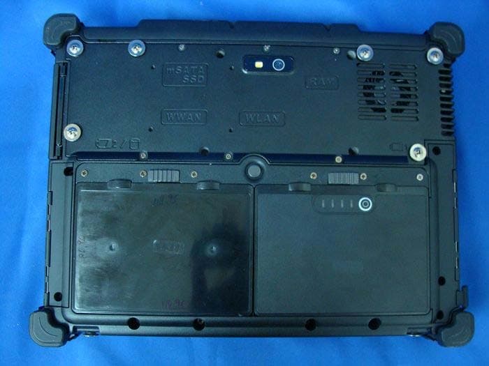
FKGTA10I
Dec 06, 2012Tablet PC
Equipment Class
DTS - Digital Transmission System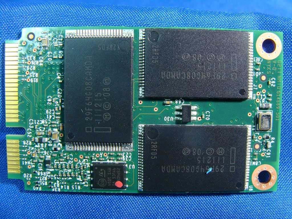
FKGT7Q
Jun 27, 2012Tablet PC
Equipment Class
DSS - Part 15 Spread Spectrum Transmitter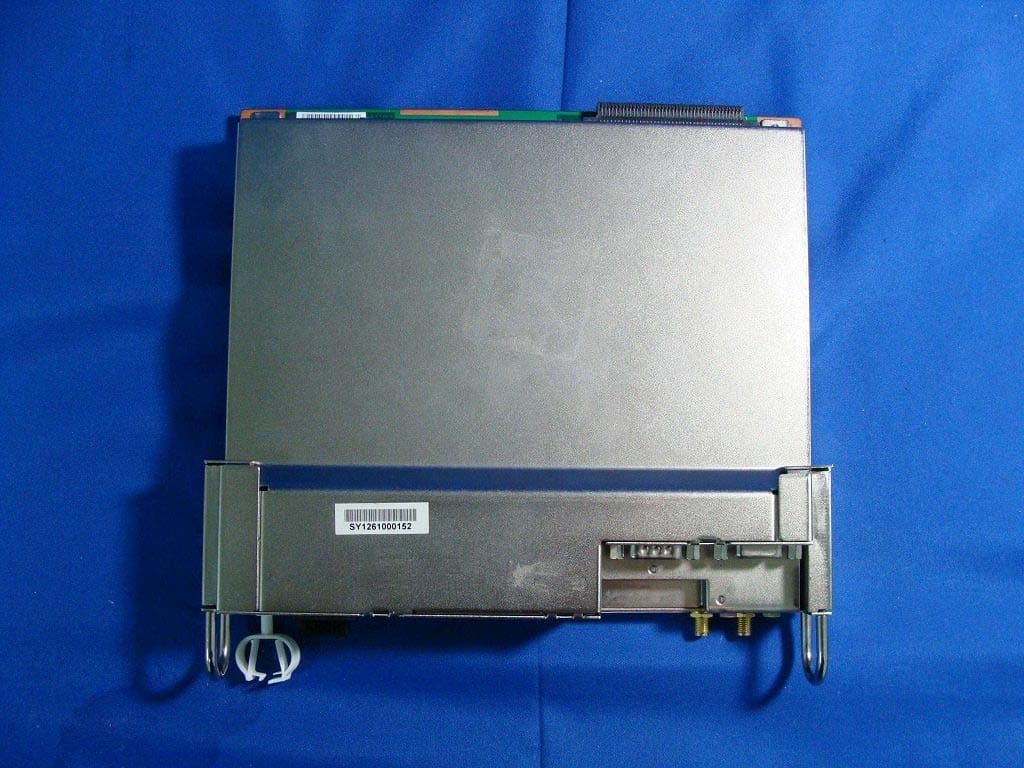
FKGPN1H
Sep 18, 2011Plug-In PC
Equipment Class
DTS - Digital Transmission System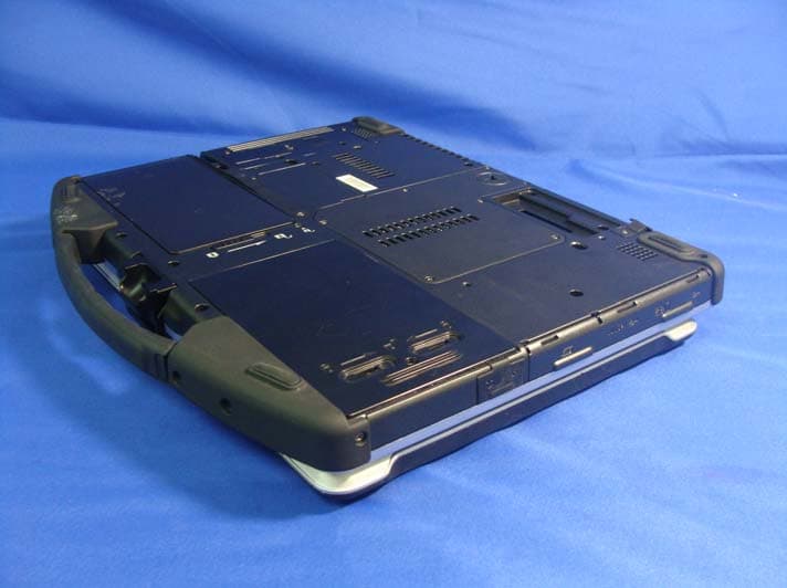
FKGU12C
Nov 03, 2010Notebook PC
Equipment Class
DTS - Digital Transmission System