G3OG-40G-TUBE
ACE INTERNATIONAL ELECTRONICS LTD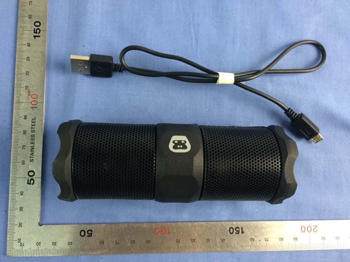
Click to zoom
Application Details
- Equipment Class
- DSS - Part 15 Spread Spectrum Transmitter
- Date of Grant
- Apr 21, 2015
- Application Purpose
- Original Equipment
- Date of Application
- Apr 21, 2015
- Equipment Note
- G-TUBE
- Frequency Range
- 2402.00000000 - 2480.00000000
- Country
- China
Documents & Files
Document Text
Text extracted from the exhibit documents filed with the FCC. Open a document above to read the original.
Users Manual
Waterproof Bluetooth Wireless G-?? All Weather Rechargeable WIRELESS TRAVEL SPEAKER G-TUBEG-TUBE UPDATE ICONS?? PACKAGE CONTENTS: • G-TUBE Wireless Travel Speaker • USB Charging Cable • User Guide Welcome Thanks for purchasing G-TUBE and joining G-Project. With just the right combination of performance, durability, features, and style at the right price, our goal is to provide rugged speakers and accessories that fit your lifestyle. We hope you agree. If you need a hand using your new G-TUBE, we’re here to help. Email us at [email protected] or give us a call Monday - Friday at 1-855-896-1795 between 8AM - 5PM CST. STOP BY AND SAY HELLO TO US: A NEW SONG EVERYDAY: facebook.com/gprojectgear twitter.com/gprojectgear instagram.com/gprojectgear We’ve got a new song for you everyday and a collection of playlists to get you going. Have a listen at songs.gprojectgear.com WIRELESS TRAVEL SPEAKER G-TUBEG-TUBE Blue LED (Bluetooth) Red LED (Charging) White LED (Power) Volume – Power On/Off Bluetooth Pair Volume + Play/Pause Skip forward/Skip back USB Charging Jack Line-in Jack Headphone Jack NOTE: Metal carry clip is used for easy carrying. You can clip G-TUBE onto your shoulder strap and have your earbuds plugged right into it. You can use G-TUBE as a "remote control" as well for volume and play control WIRELESS TRAVEL SPEAKER G-TUBEG-TUBE Metal Clip White LED OFF OFF ON ON ON ON ON OFF Red LED OFF ON OFF ON OFF Flash once every 3 secs Flash once every 2 secs OFF Battery Status FULL NOT FULL FULL NOT FULL NOT FULL LOW VERY LOW NO POWER Power Status OFF OFF ON ON ON ON ON OFF Speaker Status –– Battery Charging –– Battery Charging Using Battery Power Battery Low Battery VERY Low Will Not Power On LED INDICATORS Bluetooth LED: When G-TUBE is in paring mode, the Bluetooth LED will flash blue. Once G-TUBE has paired successfully with a Bluetooth compatible device, the Bluetooth LED will turn solid blue. Power / Charging LED: The white and red LEDs indicate the following statuses: Bluetooth LED Normal Flash 1st Flash 3rd Red LED Normal Flash 3rd Flash 1st White LED Normal Flash 2nd Flash 2nd Mode Default Mode Change Back to Default Power Status ON ON ON Speaker Status Headphone Out Daisy Chain Headphone Out MODE CHANGE INDICATORS For modes change3 LEDs indicate the following status: NOTE: While in modes changeLED flash only once in sequence. WIRELESS TRAVEL SPEAKER G-TUBEG-TUBE GETTING CHARGED UP G-TUBE includes a Micro USB power jack on the side (located under the External Jack Cover). Below are two ways you can charge G-TUBE. 1 Connect G-TUBE to a USB powered port on your computer or laptop (PC/MAC) using the supplied USB charging cable. 2 You can also charge G-TUBE by connecting G-TUBE to a USB power adaptor (not included) via the supplied USB charging cable. NOTES: When fully charged, the G-TUBE battery will provide playback time of more than 6 hours, based on volume level and type of music. Approximate time to fully recharge the G-TUBE battery is 3.5 hours. GET IN CONTROL POWER ON / OFF Press the POWER button to turn G-TUBE on and again to turn G-TUBE off. VOLUME CONTROLS Increase or decrease the volume by using the + or – buttons. G-TUBE will remember the volume setting when it is turned off. WIRELESS TRAVEL SPEAKER G-TUBEG-TUBE CHANGING MODES The default mode is" headphone out", to switch to "daisy chain" mode from the default setting, press and hold + and – buttons and the 3 LEDs will flash from the first one to the third one, indicate “headphone out” mode has swiched to "daisy chain" mode. To return to the default “headphone out” mode, press and hold + and – buttons and the 3 LEDs will flash from the third one to the first one. HEAPHONE MODE Connect your earbuds or headphones to the Headphone jack on G-TUBE and initiate playback for private listening. DAISY CHAIN MODE Connect another G-TUBE or additional external speaker with a 3.5mm Line-in cablesold separatelyto the Headphone jack thenchange the input source to Daisy Chain mode and initiate playback. BLUETOOTH WIRELESS You can stream audio to G-TUBE from up to 33’ away using your iPod, iPhone, iPad, Android, laptop, or other A2DP Bluetooth enabled device. 1 With G-TUBE powered on, press the PAIR button to enter Bluetooth mode and the Blue LED will begin to flash. If the last paired Bluetooth device is powered on and within range with Bluetooth turned on, the device will automatically reconnect G-TUBE. If you want to connect a different Bluetooth device, press and hold the PAIR button for about two seconds, the Blue LED will begin to flash indicating G-TUBE is in pairing mode and searching for Bluetooth compatible devices. 2 Power on your Bluetooth compatible device, enable Bluetooth, then search for Bluetooth devices. Select ”G -T UBE” from the available list. 3 The Blue LED on G-TUBE will change from flashing to solid, indicating that your Bluetooth device is now connected to G-TUBE. 4 Press the PLAY/PAUSE button to begin streaming music. Press again to pause. Double tapping will skip to next track and triple tapping will skip back to the previous track. WIRELESS TRAVEL SPEAKER G-TUBEG-TUBE MUSIC PLAYBACK • Tap the PLAY button once while in Bluetooth mode to play or pause the audio playback on your Bluetooth device. • Tapping the PLAY button 2x repeatedly while in Bluetooth mode will skip to the next track on your Bluetooth device. • Tapping the PLAY button 3x repeatedly while in Bluetooth mode will skip to the previous track on your Bluetooth device. NOTES: For the best audio performance, turn the volume on your Bluetooth device all the way up then adjust G-TUBE volume to a comfortable listen level. Once your Bluetooth device has been paired with G-TUBE, it is simple to reconnect them. Make sure G-TUBE is powered on and within range then simply select ”G -T UBE” from the list on your Bluetooth device. G-TUBE can only play audio from one source at a time. If G-TUBEP is connected to a Line-in source, Bluetooth will not function. Simply…
Text truncated - open the document above for the full version.
External Photos
Report No: C150316Z03 Page 1 / 3 External Photos of EUT Report No: C150316Z03 Page 2 / 3 Report No: C150316Z03 Page 3 / 3
ID Label/Location Info
Size:10×12.5mm
Internal Photos
Report No: C150316Z03 Page 1 / 8 Internal Photos of EUT Report No: C150316Z03 Page 2 / 8 Report No: C150316Z03 Page 3 / 8 Antenna RF Module Report No: C150316Z03 Page 4 / 8 Report No: C150316Z03 Page 5 / 8 Report No: C150316Z03 Page 6 / 8 Report No: C150316Z03 Page 7 / 8 Report No: C150316Z03 Page 8 / 8
RF Exposure Info
FCC RF Exposure FCC ID: G3OG‐40 Exposure category: General population/uncontrolled environment EUT Type: Production Unit Device Type: Portable Device Refer Standard: KDB 447498 D01 General RF Exposure Guidance v05r02 FCC Part 2 §2.1093 Evaluation method According to KDB447498 D01 General RF Exposure Guidance v05r01Section 4.3.1 Standalone SAR test exclusion considerations:“ Unless specifically required by the published RF exposure KDB procedures, standalone 1‐g head or body and 10‐g extremity SAR evaluation for general population exposure conditions, by measurement or numerical simulation, is not required when the corresponding SAR Test Exclusion Threshold condition, listed below, is satisfied. These test exclusion conditions are based on source‐based time‐averaged maximum conducted output power of the RF channel requiring evaluation, adjusted for tune‐up tolerance, and the minimum test separation distance required for the exposure conditions.22 The minimum test separation distance is determined by the smallest distance from the antenna and radiating structures or outer surface of the device, according to the host form factor, exposure conditions and platform requirements, to any part of the body or extremity of a user or bystander (see 5) of section 4.1). To qualify for SAR test exclusion, the test separation distances applied must be fully explained and justified by the operating configurations and exposure conditions of the transmitter and applicable host platform requirements, typically in the SAR measurement or SAR analysis report, according to the required published RF exposure KDB procedures. When no other RF exposure testing or reporting is required, a statement of justification and compliance must be included in the equipment approval, in lieu of the SAR report, to qualify for the SAR test exclusion. When required, the device specific conditions described in the other published RF exposure KDB procedures must be satisfied before applying these SAR test exclusion provisions; for example, handheld PTT two‐way radios, handsets, laptops & tablets etc.23 “ [(max. power of channel, including tune‐up tolerance, mW)/ (min. test separation distance, mm)] · [√f (GHz)] ≤ 3.0 for 1‐g SAR and≤ 7.5 for 10‐g extremity SAR, where: • f (GHz) is the RF channel transmit frequency in GHz • Power and distance are rounded to the nearest mW and mm before calculation • The result is rounded to one decimal place for comparison • 3.0 and 7.5 are referred to as the numeric thresholds in the step 2 below The test exclusions are applicable only when the minimum test separation distance is ≤ 50 mm and for transmission frequencies between 100 MHz and 6 GHz. When the minimum test separation distance is < 5 mm, a distance of 5 mm according to 5) in section 4.1 is applied to determine SAR test exclusion. Conducted Power Results Bluetooth Mode Channel Frequency(MHz) PeakConducted Output Power (dBm) 00 2402 ‐3.15 39 2441 ‐3.46 GFSK 78 2480 ‐3.86 00 2402 ‐1.98 39 2441 ‐2.27 8DPSK 78 2480 ‐2.40 00 2402 ‐2.58 39 2441 ‐2.72 π/4DQPSK 78 2480 ‐3.75 Manufacturing tolerance Bluetooth GFSK (Peak) Channel Channel 00 Channel 39 Channel 78 Target (dBm) ‐3.0 ‐3.0 ‐3.0 Tolerance ±(dB) 1.0 1.0 1.0 8DPSK (Peak) Channel Channel 00 Channel 39 Channel 78 Target (dBm) ‐1.0 ‐2.0 ‐2.0 Tolerance ±(dB) 1.0 1.0 1.0 π/4 D Q P S K (Peak) Channel Channel 00 Channel 39 Channel 78 Target (dBm) ‐2.0 ‐2.0 ‐3.0 Tolerance ±(dB) 1.0 1.0 1.0 Evaluation Results RF output power (including tune‐up tolerance) Band/Mode f (GHz) Antenna Distance (mm) dBm mW SAR Test Exclusion Threshold SAR Test Exclusion BT* 2.450 0 0 1 0.313<3.0 Yes Conclusion The measurement results comply with the FCC Limit per 47 CFR 2.1093 for the uncontrolled RF Exposure and SAR Exclusion Threshold per KDB 447498 v05r02. .......................End of Report.........................
Test Report
Report No.: C150316Z03-RP1 FCC ID: G3OG-40 Page 1 / 61 FCC 47 CFR PART 15 SUBPART C TEST REPORT For G-TUBE Model: G-40,IP-4909 Brand: G-PROJECT,OHAYO Test Report Number: C150316Z03-RP1 Prepared for ACE INTERNATIONAL ELECTRONICS LTD. Unit 2308, 23th FLOOR RILEY HOUSE 88 LEI MUK ROAD, KWAI CHUNG, N.T HONG KONG Prepared by COMPLIANCE CERTIFICATION SERVICES (SHENZHEN) INC. No.10-1, Mingkeda Logistics Park, No.18, Huanguan South Rd., Guan Lan Town, Baoan District, Shenzhen China TEL: 86-755-28055000 FAX: 86-755-28055221 Issued Date: April 3, 2015 Note: This report shall not be reproduced except in full, without the written approval of Compliance Certification Services Inc. This document may be altered or revised by Compliance Certification Services Inc. personnel only, and shall be noted in the revision section of the document. The client should not use it to claim product endorsement by TAF, A2LA, NVLAP, NIST, CNAS or any government agencies. The test result of this report relate only to the tested sample identified in this report. 检 测 CNAS L4818 Report No.: C150316Z03-RP1 FCC ID: G3OG-40 Page 2 of 61 This report shall not be reproduced except in full, without the written approval of Compliance Certification Services. Revision History Rev. Issue Date Revisions Effect Page Revised By 00 April 3, 2015 Initial Issue ALL Amzula Chen Report No.: C150316Z03-RP1 FCC ID: G3OG-40 Page 3 of 61 This report shall not be reproduced except in full, without the written approval of Compliance Certification Services. TABLE OF CONTENTS 1. TEST RESULT CERTIFICATION .....................................................................................4 2. EUT DESCRIPTION..........................................................................................................5 3. TEST METHODOLOGY....................................................................................................6 3.1 DESCRIPTION OF TEST MODES.................................................................................6 4. FACILITIES AND ACCREDITATIONS .............................................................................7 4.1 FACILITIES....................................................................................................................7 4.2 ACCREDITATIONS .......................................................................................................7 4.3 MEASUREMENT UNCERTAINTY.................................................................................7 5. SETUP OF EQUIPMENT UNDER TEST ..........................................................................8 5.1 SETUP CONFIGURATION OF EUT ..............................................................................8 5.2 SUPPORT EQUIPMENT ..............................................................................................8 6. FCC PART 15.247 REQUIREMENTS ..............................................................................9 6.1 20DB BANDWIDTH .......................................................................................................9 6.2 ANTENNA GAIN ..........................................................................................................14 6.3 PEAK POWER .............................................................................................................15 6.4 PEAK POWER SPECTRAL DENSITY.........................................................................17 6.5 BAND EDGES MEASUREMENT.................................................................................18 6.6 FREQUENCY SEPARATION ......................................................................................28 6.7 NUMBER OF HOPPING FREQUENCY.......................................................................31 6.8 TIME OF OCCUPANCY (DWELL TIME)......................................................................33 6.9 SPURIOUS EMISSIONS .............................................................................................40 6.10 POWERLINE CONDUCTED EMISSIONS.................................................................58 Report No.: C150316Z03-RP1 FCC ID: G3OG-40 Page 4 of 61 This report shall not be reproduced except in full, without the written approval of Compliance Certification Services. 1. TEST RESULT CERTIFICATION Product: G-TUBE Model: G-40,IP-4909 Brand: G-PROJECT,OHAYO Tested: March 16~April 3, 2015 Applicant: ACE INTERNATIONAL ELECTRONICS LTD. Unit 2308, 23th FLOOR RILEY HOUSE 88 LEI MUK ROAD, KWAI CHUNG, N.T HONG KONG Manufacturer: ACE INTERNATIONAL ELECTRONICS LTD. Unit 2308, 23th FLOOR RILEY HOUSE 88 LEI MUK ROAD, KWAI CHUNG, N.T HONG KONG Factory: 1. GuangZhou Lei Deng Electronics Ltd Building B, No.144 Li Jiang Road Shi Tou town, PanYu Distict, GuangZhou City, China. 2. GuangZhou GangJu Electronics Ltd. No.144, Lijiang Road, Shi Lou Town, PanYu Zone, GuangZhou City, GuangDong China APPLICABLE STANDARDS STANDARD TEST RESULT FCC 47 CFR Part 15 Subpart C No non-compliance noted We hereby certify that: The above equipment was tested by Compliance Certification Services Inc. The test data, data evaluation, test procedures, and equipment configurations shown in this report were made in accordance with the procedures given in ANSI C63.4:2009 and the energy emitted by the sample EUT tested as described in this report is in compliance with conducted and radiated emission limits of FCC Rules Part 15.207, 15.209 and 15.247. The test results of this report relate only to the tested sample EUT identified in this report. Approved by: Reviewed by: Sunday Hu Supervisor of EMC Dept. Compliance Certification Service Inc. Ruby Zhang Supervisor of Report Dept. Compliance Certification Service Inc. Report No.: C150316Z03-RP1 FCC ID: G3OG-40 Page 5 of 61 This report shall not be reproduced except in full, without the written approval of Compliance Certification Services. 2. EUT DESCRIPTION Product G-TUBE Model Number G-40,IP-4909 Brand G-PROJECT,OHAYO Model Discrepancy They are the same product except bran…
Text truncated - open the document above for the full version.
Test Setup Photos
Report No.: C150316Z03-RP1 FCC ID : G3OG-40 Page 1 / 2 PHOTOGRAPHS OF THE TEST CONFIGURATION RADIATED EMISSION TEST Report No.: C150316Z03-RP1 FCC ID : G3OG-40 Page 2 / 2 CONDUCTED EMISSION TEST
Contact Information
Applicant
judy zhang(clerk)
Test Firm
Compliance Certification Services (Shenzhen) Inc.Harry Li
Technical Specifications
| # | Rule Parts | Frequency Range | Power Output |
|---|---|---|---|
| 1 | 15C | 2.40 GHz - 2.48 GHz | 634.00 µW |
Other Applications from ACE INTERNATIONAL ELECTRONICS LTD
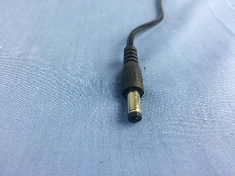
G3OCR50
Apr 20, 2015Wireless speaker and alarm clock with phone charger
Equipment Class
DSS - Part 15 Spread Spectrum Transmitter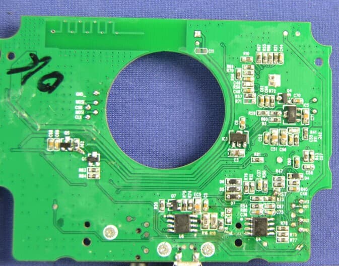
G3OG-60
Jul 29, 2014G-DROP Waterproof Wireless Speaker
Equipment Class
DSS - Part 15 Spread Spectrum Transmitter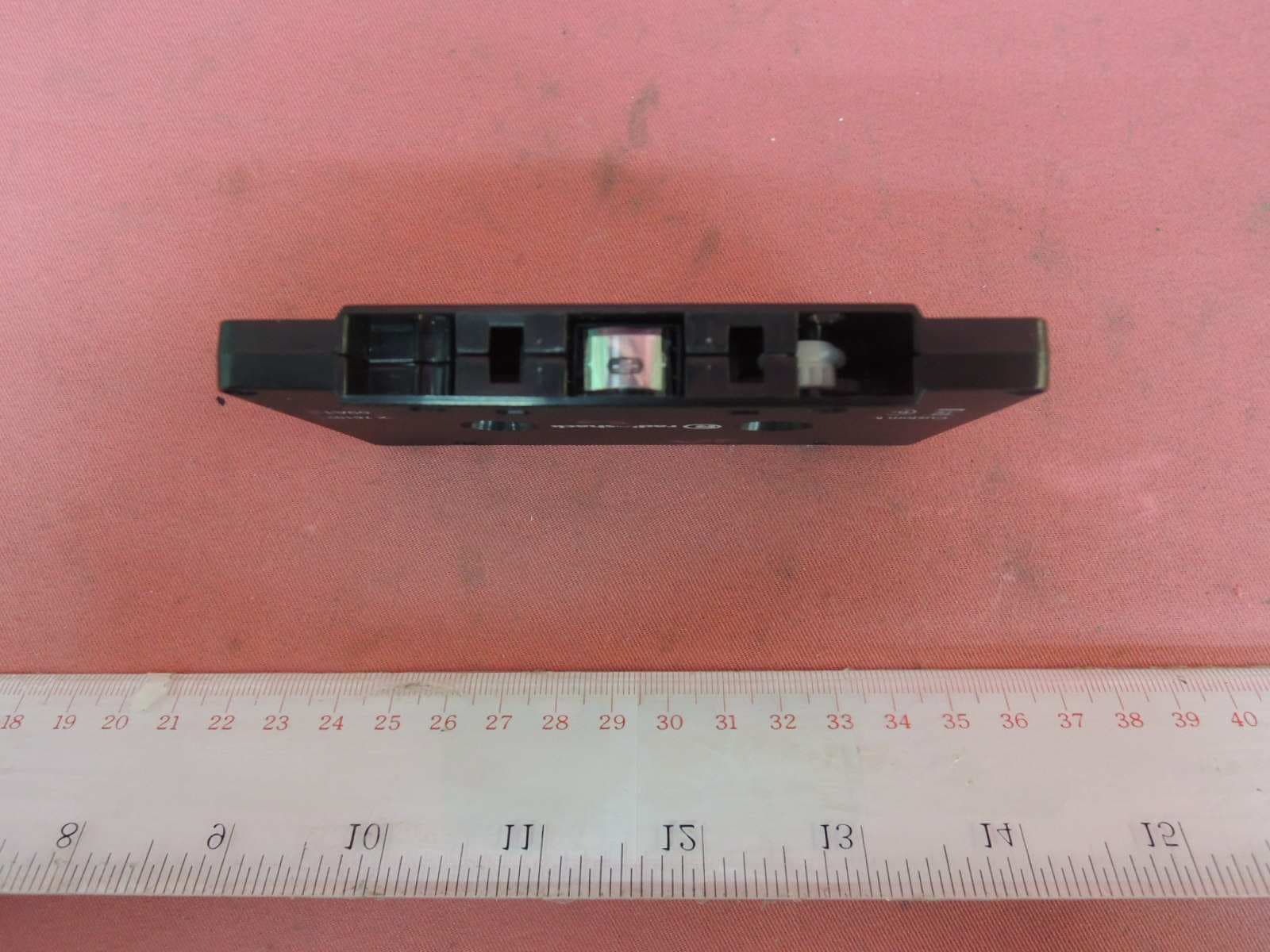
G3O1201526
Oct 19, 2013Bluetooth Cassette Adapter
Equipment Class
DXX - Part 15 Low Power Communication Device Transmitter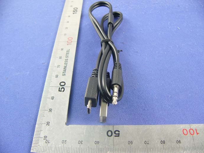
G3OG-20X
Dec 16, 2012G-POP WIRELESS TRAVEL SPEAKER
Equipment Class
DSS - Part 15 Spread Spectrum Transmitter
G3OG-50
Aug 06, 2012G-GRIP
Equipment Class
DSS - Part 15 Spread Spectrum Transmitter