GKRMPX001GSM Transceiver with WLAN and Bluetooth
Compal Electronics Inc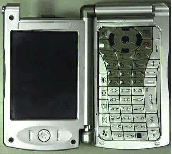
Click to zoom
Application Details
- Equipment Class
- DTS - Digital Transmission System
- Date of Grant
- Nov 30, 2004
- Application Purpose
- Original Equipment
- Date of Application
- Sep 06, 2004
- Equipment Note
- GSM Transceiver with WLAN and Bluetooth
- Frequency Range
- 2402.00000000 - 2480.00000000
- Company
- Compal Electronics Inc
- Country
- Taiwan
Documents & Files
Document Text
Text extracted from the exhibit documents filed with the FCC. Open a document above to read the original.
Users Manual
FCC ID: GKRMPX001 User’s Manual A preliminary draft copy of the manual follows: EXHIBIT 8 START HERE > MPx GSM 1 Welcome Welcome to the world of Motorola MOTOPro devices. Your selection, the Motorola MPx, delivers to you simplified communications, increased productivity, and the control to develop a superior mobile experience whether at work, at home, on the road or at play. 2 Phone Mode Main Screen Ear Piece Voi c e D i a l Button Talk Butt on Contacts Button Game Pad Keypad 3 Landscape Mode Menu Button Inbox Button Start Button Fn Button Camera Button OK Button Power/End Button 4 Front Panel 5 Back Panel 6 Motorola, Inc. Consumer Advocacy Office 1307 East Algonquin Road Schaumburg, IL 60196 1-800-331-6456 (United States) 1-888-390-6456 (TTY/TDD United States) 1-800-461-4575 (Canada) www.motorola.com (United States) www.motorola.ca (Canada) MOTOROLA and the Stylized M Logo are registered in the US Patent & Trademark Office. The Bluetooth trademarks are owned by their proprietor and used by Motorola, Inc. under license. Java and all other Java-based marks are trademarks or registered trademarks of Sun Microsystems, Inc. in the U.S. and other countries. All other product or service names are the property of their respective owners. © Motorola, Inc. 2004 The information contained in Motorola's user's guides is believed to be correct at the time of printing. Motorola reserves the right to change or modify any information or specifications without notice. The contents of Motorolas user's guides are provided as is. Except as required by applicable law, no warranties of any kind, either express or implied, including, but not limited to, the implied warranties of merchantability and fitness for a particular purpose, are made in relation to the accuracy, reliability, or contents of this guide. Caution: Changes or modifications made in the radio phone, not expressly approved by Motorola, will void the user’s authority to operate the equipment. Manual number:O 7 Contents Welcome . . . . . . . . . . . . . . . . . . . . . . . . . . . . . . . . . . . . . . . 1 Phone Mode . . . . . . . . . . . . . . . . . . . . . . . . . . . . . . . . . . . 2 Landscape Mode . . . . . . . . . . . . . . . . . . . . . . . . . . . . . . . 3 Front Panel . . . . . . . . . . . . . . . . . . . . . . . . . . . . . . . . . . . . 4 Back Panel . . . . . . . . . . . . . . . . . . . . . . . . . . . . . . . . . . . . 5 Safety and General Information . . . . . . . . . . . . . . . . . . . 11 Getting Started. . . . . . . . . . . . . . . . . . . . . . . . . . . . . . . . . 18 Package Content . . . . . . . . . . . . . . . . . . . . . . . . . . . . . . 18 About This Guide . . . . . . . . . . . . . . . . . . . . . . . . . . . . . . 18 Installing and Removing the SIM Card . . . . . . . . . . . . . . 19 Installing and Removing the SD/MMC Card . . . . . . . . . . 21 Battery Use . . . . . . . . . . . . . . . . . . . . . . . . . . . . . . . . . . . 23 Installing the Battery . . . . . . . . . . . . . . . . . . . . . . . . . . . . 25 Charging the Battery. . . . . . . . . . . . . . . . . . . . . . . . . . . . 26 Removing the Stylus . . . . . . . . . . . . . . . . . . . . . . . . . . . . 28 Opening the Phone. . . . . . . . . . . . . . . . . . . . . . . . . . . . . 29 Turning the Phone On and Off . . . . . . . . . . . . . . . . . . . . 30 Calibrating the Screen . . . . . . . . . . . . . . . . . . . . . . . . . . 31 Making a Call . . . . . . . . . . . . . . . . . . . . . . . . . . . . . . . . . 33 Answering an Incoming Call . . . . . . . . . . . . . . . . . . . . . . 34 Ending a Call /!/!/!/!/!/!/!/!/!/!/!/!/!/!/!/!/!/!!45 Learning to Use Your MPx Pocket PC Phone . . . . . . . . 35 Using Your Phone’s Menus and Features . . . . . . . . . . . . 35 Entering Information . . . . . . . . . . . . . . . . . . . . . . . . . . . . 40 Adjusting Phone Volume. . . . . . . . . . . . . . . . . . . . . . . . . 48 Using the External Display . . . . . . . . . . . . . . . . . . . . . . . 50 Checking Your Phone Connection . . . . . . . . . . . . . . . . . 50 Setting Your Phone to Flight Mode . . . . . . . . . . . . . . . . . 51 8 Using a Headset . . . . . . . . . . . . . . . . . . . . . . . . . . . . . . 52 Using a Remote PTT Button . . . . . . . . . . . . . . . . . . . . . 52 Programs. . . . . . . . . . . . . . . . . . . . . . . . . . . . . . . . . . . . 53 Using the External Display . . . . . . . . . . . . . . . . . . . . . . 55 Setting Up Your Phone. . . . . . . . . . . . . . . . . . . . . . . . . . 61 Device Settings . . . . . . . . . . . . . . . . . . . . . . . . . . . . . . . 61 Calling Features . . . . . . . . . . . . . . . . . . . . . . . . . . . . . . . 64 The Dialer Screen . . . . . . . . . . . . . . . . . . . . . . . . . . . . . 64 Making a Call . . . . . . . . . . . . . . . . . . . . . . . . . . . . . . . . 65 Taking a Note during a Call . . . . . . . . . . . . . . . . . . . . . . 70 Putting a Call on Hold . . . . . . . . . . . . . . . . . . . . . . . . . . 72 Managing Your Contacts . . . . . . . . . . . . . . . . . . . . . . . . 73 Additional Dialing Information . . . . . . . . . . . . . . . . . . . . 79 Messaging Features. . . . . . . . . . . . . . . . . . . . . . . . . . . . 81 Email Messages . . . . . . . . . . . . . . . . . . . . . . . . . . . . . . 81 SMS Messages . . . . . . . . . . . . . . . . . . . . . . . . . . . . . . . 86 MMS Messages . . . . . . . . . . . . . . . . . . . . . . . . . . . . . . 87 Viewing Messages . . . . . . . . . . . . . . . . . . . . . . . . . . . . 93 Personalizing Your MPx. . . . . . . . . . . . . . . . . . . . . . . . . 97 Phone Settings . . . . . . . . . . . . . . . . . . . . . . . . . . . . . . 104 Getting More Out of Your Phone. . . . . . . . . . . . . . . . . 108 Dialing Options . . . . . . . . . . . . . . . . . . . . . . . . . . . . . . 108 Managing Your Calls . . . . . . . . . . . . . . . . . . . . . . . . . . 109 Monitoring Phone Use. . . . . . . . . . . . . . . . . . . . . . . . . 109 Network Features . . . . . . . .…
Text truncated - open the document above for the full version.
Cover Letter(s)
COMPAL ELECTRONICS, INC. Date: 2004/8/26 Federal Communications Commission Authorization and Evaluation Division Equipment Authorization Branch 7435 Oakland Mills Road Columbia, MD 21046 To whom it may concern: We, the undersigned, hereby authorize Motorola Inc. to act on our behalf in all matters relating to applications for equipment authorization ( MPx ), including the signing of all documents relating to these matters. Any and all acts carried out by Electronic Technology Systems Dr. Genz GmbH on our behalf shall have the same effects as acts of our own. We also hereby certify that no party to this application is subject to a denial of benefits, including FCC benefits, pursuant to Section 5301 of the Anti-Drug Abuse Act of 1988, 21 U.S.C. 862. Sincerely, Signature: _________________ Name: Jerry Chien Title: EMC Design Manager Company: Compal Electronics, Inc. Tel: +886-2-87978599
Cover Letter(s)
APPLICANT: Compal Electronics, Inc. FCC ID: GKRMPX001 September 8, 2004 CONFIDENTIALITY REQUEST CONTAINED WITHIN Federal Communications Commission Authorization and Evaluation Division 7435 Oakland Mills Road Columbia, Maryland 21046 Re: Application for Cellular/PCS Transceiver Certification Gentlemen: Application: Acting as an agent for Compal Electronics, Inc.; Motorola, Inc., Personal Communications Sector, 600 N. U.S. Highway 45, Libertyville, Illinois 60048-1286 herein submits: Application for Equipment Authorization for Certification of Cellular Transceiver, FCC ID: GKRMPX001. Confidentiality: Pursuant to Section 0.459 of the Commission's rules (CFR 47), confidentiality is requested for portions of the material contained in this application and that the identified material be withheld from public inspection following the grant of this authorization. This material contains trade secrets and confidential information not customarily released to the public and which is otherwise not generally available to the public. Confidentiality is requested for the following exhibits: • Exhibit 4 Block Diagrams • Exhibit 5 Schematics • Exhibit 10 Parts List • Exhibit 12 Operational Description Description: This equipment is a GSM portable transceiver, which operates in the 850 MHz and 1900 MHz PCS bands. It also contains 2.4 GHz Bluetooth and 802.11b functions. Note: This device contains 900 MHz and1800 MHz GSM functions that are not operational in U.S. Territories. Contact Information: Please contact me by telephone at (847) 523-6167or by e-mail ( [email protected]), if there are questions or additional information needed concerning this filing. Regards, Andrew J. Bachler FCC Liaison Motorola Personal Communications Sector 600 N. U.S. Highway 45 Libertyville, IL 60048-5343 Exhibit 13
External Photos
FCC ID: GKRMPX001 EXHIBIT 3A Rear View with Battery Removed Showing ID Label Rear View Front View FCC ID: GKRMPX001 EXHIBIT 3B Flip Open Views
ID Label/Location Info
FCC ID: GKRMPX001 FCC IDENTIFICATION (NAMEPLATE) INFORMATION FCC ID: GKRMPX001 The FCC label shown is representative of the label that will appear on the radio when in production. It will be placed on the outside of the equipment as shown in Exhibit 3. Other information may also be included on this label. EXHIBIT 1
Internal Photos
FCC ID: GKRMPX001 EXHIBIT 9A Rear ViewFront View Covers Removed Front View FCC ID: GKRMPX001 EXHIBIT 9B Internal Housing Views
Internal Photos
FCC ID: GKRMPX001 EXHIBIT 9A W-LAN Antenna BT Antenna GSM Antenna Connections and Location GSM Antenna W-LAN Module BT Chipset GSM Chipset
Internal Photos
FCC ID: GKRMPX001 EXHIBIT 9Ca W-LAN Antenna BT Antenna GSM Antenna Connections and Location GSM Antenna Connections Antenna in Housing W-LAN Module BT Chipset GSM Chipset
RF Exposure Info
APPLICANT: MOTOROLA, INC. FCC ID: GKRMPX001 E E x x h h i i b b i i t t 1 1 1 1 P P a a g g e e 1 1 Exhibit 11: SAR Test Report GKRMPX001 Date of test: Date of Report: 08/19/2004 to 08/31/2004 08/31/2004 Laboratory: Motorola Personal Communications Sector Product Safety & Compliance Laboratory 600 N. US Highway 45 Room: MW113 Libertyville, Illinois 60048 Test Responsible: Albert Patapack Senior Staff Engineer Accreditation: This laboratory is accredited to ISO/IEC 17025-1999 to perform the following tests: Tests: Procedures: Electromagnetic Specific Absorption Rate ANSI/IEEE C95.1-1992, 1999 (SAR) IEEE C95.3-1991 IEEE P1528 (DRAFT) FCC OET Bulletin 65 (including Supplements A, B, C) Australian Communications Authority Radio Communications (Electromagnetic Radiation – Human Exposure) Standard 1999 CENELEC EN 50361 (2001) Simulated Tissue Preparation APP-0247 RF Power Measurement DOI-0876, 0900, 0902, 0904, 0915 On the following products or types of products: Wireless Communications Devices (Examples): Two Way Radios; Portable Phones (including Cellular, Licensed Non-Broadcast and PCS); Low Frequency Readers; and Pagers A2LA certificate #1651-01 Statement of Compliance: Motorola declares under its sole responsibility that portable cellular telephone FCC ID GKRMPX001 to which this declaration relates, is in conformity with the appropriate General Population/Uncontrolled RF exposure standards, recommendations and guidelines (FCC 47 CFR §2.1093). It also declares that the product was tested in accordance with the appropriate measurement standards, guidelines and recommended practices. Any deviations from these standards, guidelines and recommended practices are noted below: (none) ©Motorola, Inc. 2004 This test report shall not be reproduced except in full, without written approval of the laboratory. The results and statements contained herein relate only to the items tested. The names of individuals involved may be mentioned only in connection with the statements or results from this report. Motorola encourages all feedback, both positive and negative, on this test report. APPLICANT: MOTOROLA, INC. FCC ID: GKRMPX001 E E x x h h i i b b i i t t 1 1 1 1 P P a a g g e e 2 2 Table of Contents 1. INTRODUCTION..............................................................................................................................3 2. DESCRIPTION OF THE DEVICE UNDER TEST......................................................................................3 2.1 Antenna description.................................................................................................................................................................3 2.2 Device description.....................................................................................................................................................................3 3. TEST EQUIPMENT USED...................................................................................................................4 3.1 Dosimetric System...................................................................................................................................................................4 3.2 Additional Equipment...............................................................................................................................................................4 4. ELECTRICAL PARAMETERS OF THE TISSUE SIMULATING LIQUID......................................................5 5. SYSTEM ACCURACY VERIFICATION.................................................................................................6 6. TEST RESULTS................................................................................................................................7 6.1 Head Adjacent Test Results....................................................................................................................................................7 6.2 Body Worn Test Results.......................................................................................................................................................10 APPENDIX 1: SAR DISTRIBUTION COMPARISON FOR SYSTEM ACCURACY VERIFICATION.................13 APPENDIX 2: SAR DISTRIBUTION PLOTS FOR PHANTOM HEAD ADJACENT USE.................................14 APPENDIX 3: SAR DISTRIBUTION PLOTS FOR BODY WORN CONFIGURATION...................................17 APPENDIX 4: PROBE CALIBRATION CERTIFICATE............................................................................19 APPENDIX 5: DIPOLE CHARACTERIZATION CERTIFICATE.................................................................20 APPENDIX 6: MEASUREMENT UNCERTAINTY BUDGET.......................................................................21 APPENDIX 7: PHOTOGRAPHS OF DEVICE UNDER TEST..................................................................24 APPLICANT: MOTOROLA, INC. FCC ID: GKRMPX001 E E x x h h i i b b i i t t 1 1 1 1 P P a a g g e e 3 3 1 Introduction The Motorola Personal Communications Sector Product Safety Laboratory has performed measurements of the maximum potential exposure to the user of portable cellular phone (FCC ID GKRMPX001). The Specific Absorption Rate (SAR) of this product was measured. The portable cellular phone was tested in accordance with FCC OET Bulletin 65 Supplement C 01-01. 2 Description of the Device Under Test 2.1 Antenna description Type Internal Location Bottom Edge, Lower Flip Length 20mm Dimensions Width 55mm Configuration PIFA 2.2 Device description FCC ID Number GKRMPX001 Serial number 004400007088915 Mode(s) of Operation GSM 850 GSM 1800 GSM 1900 GPRS 850 GPRS 1800 GPRS 1900 BlueTooth WiFi Modulation Mode(s) GSM GSM GSM GSM GSM GSM BlueTooth 802.11b Maximum Output Power Setting 33.10dBm 30.10dBm 29.90dBm 33.10dBm 30.10dBm 29.90dBm 4.00dBm 14.77dBm Duty Cycle 1:8 1:8 1:8 2:8 2:8 2:8 1:1 1:1 Transmitting Frequency Rang(s) 824.2-848.8 MHz 1710.2-1784.8 MHz 1850.2 – 1909.8 MHz 824.2-848.8 MHz 1710.2-1784.8 …
Text truncated - open the document above for the full version.
RF Exposure Info
APPLICANT: MOTOROLA, INC. FCC ID: GKRMPX001 E E x x h h i i b b i i t t 1 1 1 1 P P a a g g e e 1 1 4 4 Appendix 2 SAR distribution plots for Phantom Head Adjacent Use During the Cheek Touch SAR measurements in the 850MHz band and the 1900MHz band it was noted that the location of maximum SAR was near the bottom of the phone, near the mouth & jaw area of the phantom (as can be seen in the contour plot below). In this region, the angle of the probe with respect to the line normal to the surface is relatively large, e.g., greater than 20°. This could increase the boundary effect error to a larger level than accounted for in the uncertainty budget. To compensate for this, scans were performed with the probe tilted 20° back from vertical along the MB line. This orientation results in an angle less than 20° between the closest point on the probe- tip housing to the phantom surface in the area of maximum SAR. This probe alignment is recommended in IEEE 1528 Section 6.5.2 “Zoom Scan Recommendations”. The SAR Plots included in Appendix 2 for the 850MHz and 1900MHz head adjacent cheek touch configurations will utilize a shorter coarse scan centered in the area of the maximum SAR. sn: 4400007088915Ch# 190 Pwr Step: 5 ota Antenna Position: INTERNAL Type of Modulation: 800 gsm Battery Model #: SNN5750ADEVICE POSITION: CHEEK Accessory Model #: noneR4 TP-1131 SUGAR SAM Expanded (Rev. 2)-9Jan03 Phantom; LH Fr ont Tilt 20 Section; Position: (80°,180°); Frequency: 837 MHz Probe: ET3DV6 - SN1514-IEEE Head2; ConvF(6.08,6.08,6.08) ; Crest factor: 8.0; 835 MHz Head & Body: σ = 0.92 mho/m ε r = 43.2 ρ = 1.00 g/cm 3 Cube 7x7x7: SAR (1g): 0.305 mW/g, SAR (10g): 0.204 mW/g, (Worst-case extrapolation)Coarse: Dx = 15.0, Dy = 15.0, Dz = 15.0Penetration depth: 12.4 (10.5, 14.9) [mm]Powerdrift: 0.28 dB SAR Tot [mW/g] 2.12E-24.24E-26.36E-28.49E-21.06E-11.27E-11.48E-11.70E-11.91E-12.12E-12.33E-12.55E-12.76E-12.97E-1 08/21/04 05:58Motorola, Inc. sn: 4400007088915Ch# 190 Pwr Step: 5 ota Antenna Position: INTERNAL Type of Modulation: 800 gsm Battery Model #: SNN5750ADEVICE POSITION: CHEEK Accessory Model #: noneR4 TP-1131 SUGAR SAM Expanded (Rev. 2)-9Jan03 Phantom; RH Fr ont Tilt 20 Section; Position: (80°,180°); Frequency: 837 MHz Probe: ET3DV6 - SN1514-IEEE Head2; ConvF(6.08,6.08,6.08) ; Crest factor: 8.0; 835 MHz Head & Body: σ = 0.92 mho/m ε r = 43.2 ρ = 1.00 g/cm 3 Cube 7x7x7: SAR (1g): 0.264 mW/g, SAR (10g): 0.176 mW/g, (Worst-case extrapolation)Coarse: Dx = 15.0, Dy = 15.0, Dz = 15.0Penetration depth: 13.9 (11.0, 17.8) [mm]Powerdrift: -0.50 dB SAR Tot [mW/g] 1.78E-23.56E-25.34E-27.11E-28.89E-21.07E-11.24E-11.42E-11.60E-11.78E-11.96E-12.13E-12.31E-12.49E-1 08/21/04 07:16Motorola, Inc. sn: 4400007088915Ch# 190 Pwr Step: 5 ota Antenna Position: INTERNAL Type of Modulation: 800 gsm Battery Model #: SNN5750ADEVICE POSITION: CHEEK Accessory Model #: WIFI (continuous mod tx 11mbps/cck)R4 TP-1131 SUGAR SAM Expanded (Rev. 2)-9Jan03 Phantom; LH Fr ont Tilt 20 Section; Position: (80°,180°); Frequency: 837 MHz Probe: ET3DV6 - SN1514-IEEE Head2; ConvF(6.08,6.08,6.08) ; Crest factor: 8.0; 835 MHz Head & Body: σ = 0.92 mho/m ε r = 42.8 ρ = 1.00 g/cm 3 Cube 7x7x7: SAR (1g): 0.277 mW/g, SAR (10g): 0.183 mW/g, (Worst-case extrapolation)Coarse: Dx = 15.0, Dy = 15.0, Dz = 15.0Penetration depth: 13.0 (11.0, 15.6) [mm]Powerdrift: 0.33 dB SAR Tot [mW/g] 1.92E-23.84E-25.76E-27.69E-29.61E-21.15E-11.35E-11.54E-11.73E-11.92E-12.11E-12.31E-12.50E-12.69E-1 08/24/04 10:28Motorola, Inc. sn: 4400007088915Ch# 190 Pwr Step: 5 ota Antenna Position: INTERNAL Type of Modulation: 800 gsm Battery Model #: SNN5751ADEVICE POSITION: CHEEK Accessory Model #: noneR4 TP-1131 SUGAR SAM Expanded (Rev. 2)-9Jan03 Phantom; LH Fr ont Tilt 20 Section; Position: (80°,180°); Frequency: 837 MHz Probe: ET3DV6 - SN1514-IEEE Head2; ConvF(6.08,6.08,6.08) ; Crest factor: 8.0; 835 MHz Head & Body: σ = 0.92 mho/m ε r = 43.2 ρ = 1.00 g/cm 3 Cube 7x7x7: SAR (1g): 0.293 mW/g, SAR (10g): 0.194 mW/g * Max outside, (Worst-case extrapolation)Coarse: Dx = 15.0, Dy = 15.0, Dz = 15.0Penetration depth: 12.8 (11.1, 15.0) [mm]Powerdrift: -0.16 dB SAR Tot [mW/g] 2.09E-24.17E-26.26E-28.34E-21.04E-11.25E-11.46E-11.67E-11.88E-12.09E-12.29E-12.50E-12.71E-12.92E-1 08/21/04 07:54Motorola, Inc. sn: 4400007088915Ch# 661 / Pwr Step: 0 Antenna Position: Internal Type of Modulation: GSM 1900 Battery Model #: SNN5750A DEVICE POSITION (cheek or rotated): Cheek Accessory Model #: N/ASimulate Temp when Measured: 19.5C Simulate Temp after Test: 19.6C R4 TP-1250 GLYCOL SAM Expanded (Rev. 2)-9Jan03 Phantom; LH Fr ont Tilt 20 Section; Position: (80°,180°); Frequency: 1880 MHz Probe: ET3DV6 - SN1514-IEEE Head2; ConvF(5.03,5.03,5. 03); Crest factor: 8.0; 1880 MHz Head & Body: σ = 1.44 mho/m ε r = 38.5 ρ = 1.00 g/cm 3 Cube 7x7x7: SAR (1g): 0.112 mW/g, SAR (10g): 0.0739 mW/g, (Worst-case extrapolation)Coarse: Dx = 15.0, Dy = 15.0, Dz = 15.0Penetration depth: 12.2 (10.4, 15.0) [mm]Powerdrift: 0.57 dB SAR Tot [mW/g] 8.00E-31.60E-22.40E-23.20E-24.00E-24.80E-25.60E-26.40E-27.20E-28.00E-28.80E-29.60E-21.04E-11.12E-1 08/20/04 20:34Motorola, Inc. sn: 4400007088915Ch# 661 / Pwr Step: 0 Antenna Position: non Type of Modulation: gsm Battery Model #: snn5750a DEVICE POSITION (cheek tilted probeR4 TP-1250 GLYCOL SAM Expanded (Rev. 2)-9Jan03 Phantom; RH Fr ont Tilt 20 Section; Position: (80°,180°); Frequency: 1880 MHz Probe: ET3DV6 - SN1514-IEEE Head2; ConvF(5.03,5.03,5. 03); Crest factor: 8.0; 1880 MHz Head & Body: σ = 1.46 mho/m ε r = 38.0 ρ = 1.00 g/cm 3 Cube 7x7x7: SAR (1g): 0.143 mW/g, SAR (10g): 0.0884 mW/g * Max outside, (Worst-case extrapolation)Coarse: Dx = 15.0, Dy = 15.0, Dz = 15.0Penetration depth: 11.0 (8.7, 14.8) [mm]Powerdrift: -0.53 dB SAR Tot [mW/g] 9.79E-31.96E-22.94E-23.91E-24.89E-25.87E-26.85E-27.83E-28.81E-29.79E-21.08E-11.17E-11.27E-11.37E-1 08/21/04 21:25Motorola, Inc. sn: 4400007088915Ch# 661 Pwr Step: 0 ota Antenna Position: INTERNAL Type of Modulation: 1900 gsm Battery Model #: SNN5750ADEVICE POSITI…
Text truncated - open the document above for the full version.
RF Exposure Info
IHDT56EG1 Exhibit 11 Supplement Response Page 1 of 7 November 04, 2004 Supplement to SAR Test Report for Motorola portable cellular phone (FCC ID GKRMPX001) Prepared by: Steven Hauswirth Motorola Personal Communications Sector Product Safety Laboratory Libertyville, Illinois IHDT56EG1 Exhibit 11 Supplement Response Page 2 of 7 Summary of FCC request for additional information There was a request for additional information regarding Motorola’s SAR Test Report for Motorola portable cellular phone (FCC ID GKRMPX001) . The requested information is addressed below in the same numbering sequence received. 3) Please describe any use conditions and device test settings where GSM and LAN transmit at the same time, or describe device settings to prevent this if applicable. RESPONSE: GSM850, GSM900, GSM1800, GSM1900 can transmit simultaneously with WLAN. 4) For any cotransmitting conditions of 3), please describe how reported SAR results are applicable for exposure evaluation. RESPONSE: The reported SAR values represent the maximum measured values for each transmitting mode/band. A sum of the GSM and Wi-Fi value would represent an overestimate of the SAR for a simultaneous transmitting condition. Cheek / Touch Position Left Head Right Head f (MHz) Description Conducted Output Power (dBm) Measured (W/kg) Drift (dB) Extrapolated (W/kg) Simulate Temp (°C) Measured (W/kg) Drift (dB) Extrapolated (W/kg) Simulate Temp (°C) Channel 128 33.11 Channel 190 33.27 0.305 0.28 0.31 19.6 0.264 -0.5 0.30 19.6 Digital 850MHz Channel 251 33.17 Channel 512 30.14 Channel 661 30.11 0.112 0.57 0.11 19.6 0.143 -0.53 0.16 19.0 Digital 1900MHz Channel 810 29.96 Channel 1 14.77 Channel 6 14.77 0.0262 0.07 0.03 19.0 0.0197 -0.15 0.02 19.8 WiFi 2400Mhz Channel 11 14.77 Table 1: SAR measurement results for the portable cellular telephone FCC ID GKRMPX001 at highest possible output power. Measured against the left head in the Cheek/Touch Position. Combining the SAR values of the GSM modes and the Wi-Fi yields the following SAR values. These values are an overestimate of the SAR since these maxima don’t occur in the same location on the phone. IHDT56EG1 Exhibit 11 Supplement Response Page 3 of 7 Cheek / Touch Position Left Head Right Head f (MHz) Description Conducted Output Power (dBm) Measured (W/kg) Measured (W/kg) Channel 128 33.11 Channel 190 33.27 0.33 0.32 Digital 850MHz Channel 251 33.17 Channel 512 30.14 Channel 661 30.11 0.14 0.18 Digital 1900MHz Channel 810 29.96 Table 2: SAR measurement results for the portable cellular telephone FCC ID GKRMPX001 at highest possible output power. Measured against the left head in the Cheek/Touch Position. 15° Tilt Position Left Head Right Head f (MHz) Description Conducted Output Power (dBm) Measured (W/kg) Drift (dB) Extrapolated (W/kg) Simulate Temp (°C) Measured (W/kg) Drift (dB) Extrapolated (W/kg) Simulate Temp (°C) Channel 128 33.11 Channel 190 33.27 0.105 -0.01 0.11 19.8 0.107 -0.26 0.11 19.4 Digital 850MHz Channel 251 33.17 Channel 512 30.14 Channel 661 30.11 0.055 -0.09 0.06 19.3 0.0484 -0.05 0.05 19.0 Digital 1900MHz Channel 810 29.96 Channel 1 14.77 Channel 6 14.77 0.0064 0.62 0.01 19.8 0.0076 -0.33 0.01 19.8 WiFi 2400Mhz Channel 11 14.77 Table 3: SAR measurement results for the portable cellular telephone FCC ID IHDT56EV1 at highest possible output power. Measured against the left head in the 15° Tilt Position. Combining the SAR values of the GSM modes and the Wi-Fi yields the following SAR values. These values are an overestimate of the SAR since these maxima don’t occur in the same location on the phone. 15° Tilt Position Left Head Right Head f (MHz) Description Conducted Output Power (dBm) Measured (W/kg) Measured (W/kg) Channel 128 33.11 Channel 190 33.27 0.12 0.12 Digital 850MHz Channel 251 33.17 Channel 512 30.14 Channel 661 30.11 0.07 0.06 Digital 1900MHz Channel 810 29.96 Table 4: SAR measurement results for the portable cellular telephone FCC ID IHDT56EV1 at highest possible output power. Measured against the left head in the 15° Tilt Position. IHDT56EG1 Exhibit 11 Supplement Response Page 4 of 7 Body Worn GSM with SYN1070A with SYN1070A & Bluetooth f (MHz) Description Conducted Output Power (dBm) Measured (W/kg) Drift (dB) Extrapolated (W/kg) Simulate Temp (°C) Measured (W/kg) Drift (dB) Extrapolated (W/kg) Simulate Temp (°C) Channel 128 33.11 Channel 190 33.27 0.626 -0.11 0.64 20.0 0.678 -0.11 0.70 20.0 Digital 850MHz Channel 251 33.17 Channel 512 30.14 Channel 661 30.11 0.617 0.00 0.62 19.5 0.513 -0.12 0.53 19.5 Digital 1900MHz Channel 810 29.96 Table 5: SAR measurement results for the portable cellular telephone FCC ID GKRMPX001 at highest possible output power. Measured against the body. Body Worn WiFi with SYN1070A with SYN1070A & SNN5751A f (MHz) Description Conducted Output Power (dBm) Measured (W/kg) Drift (dB) Extrapolated (W/kg) Simulate Temp (°C) Measured (W/kg) Drift (dB) Extrapolated (W/kg) Simulate Temp (°C) Channel 1 14.77 Channel 6 14.77 0.186 0.04 0.19 19.8 0.167 -0.03 0.17 19.5 WiFi 2400Mhz Channel 11 14.77 Table 6: SAR measurement results for the portable cellular telephone FCC ID GKRMPX001 at highest possible output power. Measured against the body. Combining the SAR values of the GSM modes and the Wi-Fi yields the following SAR values. These values are an overestimate of the SAR since these maxima don’t occur in the same location on the phone. 15° Tilt Position w/o BT w/ BT f (MHz) Description Conducted Output Power (dBm) Measured (W/kg) Measured (W/kg) Channel 128 33.11 Channel 190 33.27 0.83 0.89 Digital 850MHz Channel 251 33.17 Channel 512 30.14 Channel 661 30.11 0.81 0.72 Digital 1900MHz Channel 810 29.96 Table 4: SAR measurement results for the portable cellular telephone FCC ID IHDT56EV1 at highest possible output power. Measured against the left head in the 15° Tilt Position. 5) Please describe intended use positions while transmitting in landscape mode. RESPONSE: The intended use position while transmitting in landscape mode would be…
Text truncated - open the document above for the full version.
RF Exposure Info
Page 1 of 4 December 1, 2004 Supplement to SAR Test Report for Motorola portable cellular phone (FCC ID GKRMPX001) Prepared by: Steven Hauswirth Motorola Personal Communications Sector Product Safety Laboratory Libertyville, Illinois Page 2 of 4 Summary of FCC request for additional information There was a request for additional information regarding Motorola’s SAR Test Report for Motorola portable cellular phone (FCC ID GKRMPX001) . The requested information is addressed below in the same numbering sequence received. 1) The 12 body-worn SAR plots have different relative orientations - please provide a list for these 12 plots and device orientations for each relative to GSM antenna, and whether that is device front or back in holster. Alternatively revise the affected report sections, also related to the following issues. RESPONSE: The device was positioned in the holster with the back of the unit towards the user. This orientates the unit so the antennas are in closer proximity to the user. Revised plots have been included in Appendix 1 to illustrate the placement of the unit with respect to the plots. 2) Reply to EA699206 corresp. 27896 Tables 5 & 6 are the same as Tables 5 & 8 from original report, with the second "Table 4" of reply showing the simple addition of GSM and LAN SAR values. (This assumes the references to 15 deg tilt in the caption and header row of this 2nd "Table 4" are in error.) However, highest SAR is GPRS body at 1.46 W/kg - please demonstrate how/why SAR summation is not applicable for this configuration, also considering related issues in questions here. RESPONSE: The GPRS and the Wi-Fi modes are not permitted to cotransmit. Motorola’s position is both of these modes are data transfer modes and thus only one should transfer at a time. The software in the device prevents both data modes from transmitting at the same time. 3) Body-worn LAN data appears to have incorrect liquid and probe factors - please revise. RESPONSE: Additional SAR measurements were taken using the same setup as the body worn measurements in the filing, except the Simulated Tissue was changed from 2.4GHz Head to 2.4GHz body and the Robot Software was upgraded to DASY4.4. Please see the updated table below for the results of these measurements. The output plots of these measurements are included in Appendix 2. Body Worn WiFi with SYN1070A with SYN1070A & SNN5751A f (MH…
Text truncated - open the document above for the full version.
Contact Information
Applicant
Joyce Ting(Senior RF Regulatory Compliance Engineer)
Technical Contact
MotorolaAndrew J Bachler
[email protected]847 523-6167
600 N. US Highway 45 · Libertyville, Illinois · United States
Non-Technical Contact
MotorolaAndrew J Bachler
[email protected]847 523-6167
Test Firm
Motorola Inc.Albert Patapack
Technical Specifications
| # | Rule Parts | Frequency Range | Power Output |
|---|---|---|---|
| 2 | 15C | 2.40 GHz - 2.48 GHz | 1.00 mW |
Other Applications from Compal Electronics Inc
GKRRXLN4N
May 26, 2026LGA Module
Equipment Class
CBE - Citizens Band End User DevicesGKRCMMG3L
May 08, 20265G Module
Equipment Class
CBE - Citizens Band End User DevicesGKRRMMG4
Jan 23, 20265G Module
Equipment Class
CBE - Citizens Band End User DevicesGKRRXLN3
Dec 08, 2024LGA Module
Equipment Class
CBE - Citizens Band End User DevicesGKRRMMT1
Aug 14, 2024NTN miniPCIE module
Equipment Class
TNB - Licensed Non-Broadcast Station Transmitter