GKRPA3203U-1BTMBluetooth Module
Compal Electronics Inc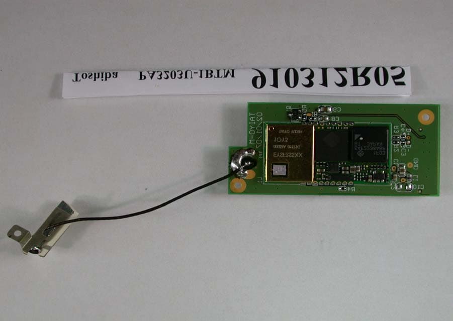
Click to zoom
Application Details
- Equipment Class
- DSS - Part 15 Spread Spectrum Transmitter
- Date of Grant
- Apr 15, 2002
- Application Purpose
- Original Equipment
- Date of Application
- Apr 15, 2002
- Equipment Note
- Bluetooth Module
- Frequency Range
- 2402.00000000 - 2480.00000000
- Company
- Compal Electronics Inc
- Country
- Taiwan
Documents & Files
Document Text
Text extracted from the exhibit documents filed with the FCC. Open a document above to read the original.
Users Manual
User's Manual1 Toshiba Pocket PC Bluetooth™ User's Manual Bluetooth™ FIRST PAGE, BOOK BLOCK 2Bluetooth SD Card™ Table of Contents Table of Contents..................................................................................... 2 Getting Started......................................................................................... 3 Notes......................................................................................................... 3 Safety Precautions................................................................................... 3 Limitation of liability................................................................................ 3 Usage conditions..................................................................................... 4 Warning..................................................................................................... 4 Caution...................................................................................................... 4 Specifications........................................................................................... 5 Setup......................................................................................................... 6 Setting Up Your Toshiba Pocket PC...................................................... 6 Enabling Bluetooth™ on Your Toshiba Pocket PC.............................. 6 Bluetooth™ Connection.......................................................................... 7 To establish Bluetooth™ connection.................................................... 7 Connect to PC via ActiveSync.............................................................. 11 Bluetooth™ Settings.............................................................................. 12 Changing the User Mode....................................................................... 12 Displaying the local device information.............................................. 13 Disconnecting/Exiting Bluetooth™ Connection................................. 14 Bluetooth Chat....................................................................................... 16 Error Messages...................................................................................... 17 Additional Information........................................................................... 20 Trademarks............................................................................................. 20 Bluetooth™ User's Manual2 User's Manual3 Getting Started Thank you very much for your purchase of this Bluetooth™ enabled PocketPC. Please be sure to read this User’s Guide before using the Bluetooth™ enabled PocketPC to ensure its proper handling. ■ Please be sure to read “Safety Precautions” in this document since these describe important safety issues. ■ After reading this document, keep it in a convenient place for future reference. Concerning the display of device certification: This product has been certified as conforming to technological standards for a wireless device as a small electrical data transmission system under electrical transmission law. Therefore, you do not need a license from a government agency to operate this system. However, the following actions are punishable by law. ■ Disassembly or modification of this product. ■ Removal of identification labels on the back of this product. Notes ■ This document cannot be reproduced in any form without the prior written permission of Toshiba. ■ The information herein is subject to change without notice. ■ We have done our utmost to ensure that the information herein is as accurate as possible. Please notify Toshiba of any required corrections. Safety Precautions ■ Please be sure to read “Safety Precautions” outlined here carefully before using Bluetooth™ and ensure that you are aware of correct handling procedures. ■ The precautions stated here provide essential information for the protection of the user and others from possible injury and property damage, and on the safe handling of the product you have purchased. ■ Please check that you fully understand the definition of the following messages (signs and graphical symbols) before going on to read the text, and always follow the instructions. Explanation of signs SignsMeaning WARNINGIndicates a potentially hazardous situation, which could result in death or serious bodily injury¹ if you do not follow instructions. CAUTIONIndicates a potentially hazardous situation, which if not avoided, could result in minor bodily injury² or property damage³. 1. Serious bodily injury refers to an injury that leaves some after effects, and requires hospital treatment or long-term treatment, such as blindness, injuries, burns (high or low temperature burns), electric shock, fractures or poisoning. 2. Minor bodily injury refers to an injury that does not require hospital treatment or long-term treatment, such as minor burns or electric shock. 3. Property damage refers to extensive damage of property, such as a structure, household effects, livestock or pets. Limitation of liability ■ Toshiba Corporation is in no way liable for any damage resulting from earthquakes, fire, actions on the part of a third party, other accidents beyond the control of Toshiba Corporation, intentional acts, negligence or misuse on the part of the user, or any usage under abnormal conditions. ■ Toshiba Corporation is in no way liable for any damage, including but not limited to change or loss of stored data, loss of business profit, interruption of business, or lost communication opportunities that are caused by usage of, or inability to use this product. ■ Toshiba Corporation is in no way liable for any damage resulting from failure to comply with the contents of this user’s guide. ■ Toshiba Corporation is in no way liable for any damage resulting from malfunction due to use with peripherals or software other than those provided by Toshiba Corporation. Bluetooth™ User's Manual3 4Bluetooth SD Card™ Usage conditions Blu…
Text truncated - open the document above for the full version.
External Photos
Page 1 ANNEX PHOTOGRAPHS OF EUT
External Photos
Page 1 ANNEX PHOTOGRAPHS OF EUT
ID Label/Location Info
FCC ID LABEL LOCATION
ID Label/Location Info
FCC ID LABEL LOCATION
Internal Photos
Page 2 Page 3 Page 4
Internal Photos
Page 2 Page 3 Page 4
Operational Description
FCC ID: GKRPA3203U-1BTM ADT No.910312R05 Operational Description The transmitter of the EUT is powered by host equipment. The antenna is PIFA antenna, and there is no antenna connector. This application is seeking for Module Approval. The output power is lower than 0dBm, so the SAR is of course lower than the limit. The other instruction, please have a look at the users manual. This device is a Frequency Hopping device with 79 hopping frequencies.
Operational Description
FCC ID: GKRPA3203U-1BTM ADT No.910312R05 Operational Description The transmitter of the EUT is powered by host equipment. The antenna is PIFA antenna, and there is no antenna connector. This application is seeking for Module Approval. The output power is lower than 0dBm, so the SAR is of course lower than the limit. The other instruction, please have a look at the users manual. This device is a Frequency Hopping device with 79 hopping frequencies.
RF Exposure Info
ADT No: 910312R05 1 FCC TEST REPORT REPORT NO.: RF910312R05 MODEL NO.: PA3203U-1BTM ACCORDING: FCC Guidelines for Human Exposure IEEE C95.1 APPLICANT: COMPAL ELECTRONICS INC. ADDRESS: No. 581, Juikuang Rd., Neihu 114, Taipei, Taiwan, R.O.C. ISSUED BY: Advance Data Technology Corporation LAB LOCATION: 47 14th Lin, Chiapau Tsun, Linko, Taipei, Taiwan, R.O.C. 0528 ILAC MRA Lab Code: 200102-0 ADT No: 910312R05 2 RF Exposure Measurement 1. Introduction 2.4 GHz frequency band is regarded specially as a dangerous band for its heating harmfulness to the human body. That’s why microwave oven is operating in this frequency band. The manufacturer whose product is working in this frequency band is obligatory to prove the harmfulness of his product. In this document, we try to prove the safety of radiation harmfulness to the human body for our product. The limit for Maximum Permissible Exposure (MPE) specified in FCC 1.1310 is followed. The Gain of the antenna used in this product is measured in a Fully Anechoic Chamber (FAC) calibrated for antenna measurement in ADT, and also the maximum total power input to the antenna is measured. Through the Friis transmission formula and the maximum gain of the antenna, we can calculate the distance, away from the product, where the limit of MPE is reached. Although the Friis transmission formula is a far field assumption, the calculated result of that is an over-prediction for near field power density. We will take that as the worst case to specify the safety range. 2. RF Exposure Limit According to FCC 1.1310: The criteria listed in the following table shall be used to evaluate the environmental impact of human exposure to radio-frequency (RF) radiation as specified in 1.1307(b) LIMITS FOR MAXIMUM PERMISSIBLE EXPOSURE (MPE) Frequency Range (MHz) Electric Field Strength (V/m) Magnetic Field Strength (A/m) Power Density (mW/cm 2 ) Average Time (minutes) (A)Limits For Occupational / Control Exposures 300-1500......F/3006 1500-100,000......56 (B)Limits For General Population / Uncontrolled Exposure 300-1500......F/15006 1500-100,000......1.030 F = Frequency in MHz ADT No: 910312R05 3 3. Friis Formula Friis transmission formula : Pd = (Pout*G) / (4*pi*r 2 ) where Pd = power density in mW/cm 2 Pout = output power to antenna in mW G = gain of antenna in linear scale Pi = 3.1416 R = distance between observation point and center of the radiator in cm Pd is the limit of MPE, 1 mW/cm 2 . If we know the maximum Gain of the antenna and the total power input to the antenna, through the calculation, we will know the distance r where the MPE limit is reached. Ref. : David K. Cheng, Field and Wave Electromagnetics, Second Edition, Page 640, Eq. (11-133). 4 EUT Operating condition The software provided by Manufacturer enabled the EUT to transmit and receive data at lowest, middle and highest channel individually. 5 Climate Condition The temperature and related humidity: 18 deg. C and 65 % RH 6. Classification This device is seeking for Module Approval authorization. It could be Mobile or Portable device after it is integrated into the host. ADT No: 910312R05 4 7 Test Results 7.1 Antenna Gain The maximum Gain measured in Fully Anechoic Chamber is 1dBi or 1.26(numeric). 7.2 Output Power Into Antenna & RF Exposure Distance : CHANNEL CHANNEL FREQUENCY (MHz) OUTPUT POWER TO ANTENNA (mW) MINIMUM ALLOWABLE DISTANCE ( r ) FROM SKIN (Centi-Meter) 124120.560.24 624370.600.24 1124620.690.26 The minimum allowable distance is very close to the enclosure of the antenna. So, the user has no need to worry about the harmfulness of radiation. But it is recommended to always keep, at least, 20 cm separation distance with the antenna.
RF Exposure Info
ADT No: 910312R05 1 FCC TEST REPORT REPORT NO.: RF910312R05 MODEL NO.: PA3203U-1BTM ACCORDING: FCC Guidelines for Human Exposure IEEE C95.1 APPLICANT: COMPAL ELECTRONICS INC. ADDRESS: No. 581, Juikuang Rd., Neihu 114, Taipei, Taiwan, R.O.C. ISSUED BY: Advance Data Technology Corporation LAB LOCATION: 47 14th Lin, Chiapau Tsun, Linko, Taipei, Taiwan, R.O.C. 0528 ILAC MRA Lab Code: 200102-0 ADT No: 910312R05 2 RF Exposure Measurement 1. Introduction 2.4 GHz frequency band is regarded specially as a dangerous band for its heating harmfulness to the human body. That’s why microwave oven is operating in this frequency band. The manufacturer whose product is working in this frequency band is obligatory to prove the harmfulness of his product. In this document, we try to prove the safety of radiation harmfulness to the human body for our product. The limit for Maximum Permissible Exposure (MPE) specified in FCC 1.1310 is followed. The Gain of the antenna used in this product is measured in a Fully Anechoic Chamber (FAC) calibrated for antenna measurement in ADT, and also the maximum total power input to the antenna is measured. Through the Friis transmission formula and the maximum gain of the antenna, we can calculate the distance, away from the product, where the limit of MPE is reached. Although the Friis transmission formula is a far field assumption, the calculated result of that is an over-prediction for near field power density. We will take that as the worst case to specify the safety range. 2. RF Exposure Limit According to FCC 1.1310: The criteria listed in the following table shall be used to evaluate the environmental impact of human exposure to radio-frequency (RF) radiation as specified in 1.1307(b) LIMITS FOR MAXIMUM PERMISSIBLE EXPOSURE (MPE) Frequency Range (MHz) Electric Field Strength (V/m) Magnetic Field Strength (A/m) Power Density (mW/cm 2 ) Average Time (minutes) (A)Limits For Occupational / Control Exposures 300-1500......F/3006 1500-100,000......56 (B)Limits For General Population / Uncontrolled Exposure 300-1500......F/15006 1500-100,000......1.030 F = Frequency in MHz ADT No: 910312R05 3 3. Friis Formula Friis transmission formula : Pd = (Pout*G) / (4*pi*r 2 ) where Pd = power density in mW/cm 2 Pout = output power to antenna in mW G = gain of antenna in linear scale Pi = 3.1416 R = distance between observation point and center of the radiator in cm Pd is the limit of MPE, 1 mW/cm 2 . If we know the maximum Gain of the antenna and the total power input to the antenna, through the calculation, we will know the distance r where the MPE limit is reached. Ref. : David K. Cheng, Field and Wave Electromagnetics, Second Edition, Page 640, Eq. (11-133). 4 EUT Operating condition The software provided by Manufacturer enabled the EUT to transmit and receive data at lowest, middle and highest channel individually. 5 Climate Condition The temperature and related humidity: 18 deg. C and 65 % RH 6. Classification This device is seeking for Module Approval authorization. It could be Mobile or Portable device after it is integrated into the host. ADT No: 910312R05 4 7 Test Results 7.1 Antenna Gain The maximum Gain measured in Fully Anechoic Chamber is 1dBi or 1.26(numeric). 7.2 Output Power Into Antenna & RF Exposure Distance : CHANNEL CHANNEL FREQUENCY (MHz) OUTPUT POWER TO ANTENNA (mW) MINIMUM ALLOWABLE DISTANCE ( r ) FROM SKIN (Centi-Meter) 124120.560.24 624370.600.24 1124620.690.26 The minimum allowable distance is very close to the enclosure of the antenna. So, the user has no need to worry about the harmfulness of radiation. But it is recommended to always keep, at least, 20 cm separation distance with the antenna.
Test Report
FCC ID: GKRPA3203U-1BTM Report No.: RF910312R05 1 Issued: March 20, 2002 FCC TEST REPORT REPORT NO.: RF910312R05 MODEL NO.: PA3203U-1BTM RECEIVED: Mar. 12, 2002 TESTED: Mar. 14, 2002 APPLICANT: COMPAL ELECTRONICS INC. ADDRESS: No. 581, Juikuang Rd., Neihu 114, Taipei, Taiwan, R.O.C. ISSUED BY: Advance Data Technology Corporation LAB LOCATION: 47 14th Lin, Chiapau Tsun, Linko, Taipei, Taiwan, R.O.C. This test report consists of 60 pages in total. It may be duplicated completely for legal use with the approval of the applicant. It should not be reproduced except in full, without the written approval of our laboratory. The client should not use it to claim product endorsement by CNLA, NVLAP or any government agencies. The test results in the report only apply to the tested sample. 0528 ILAC MRA Lab Code: 200102-0 FCC ID: GKRPA3203U-1BTM Report No.: RF910312R05 2 Issued: March 20, 2002 TABLE OF CONTENTS 1CERTIFICATION .......................................................................................................... 4 2SUMMARY OF TEST RESULTS.................................................................................. 5 3GENERAL INFORMATION........................................................................................... 6 3.1GENERAL DESCRIPTION OF EUT............................................................................. 6 3.2DESCRIPTION OF TEST MODES............................................................................... 7 3.3GENERAL DESCRIPTION OF APPLIED STANDARDS.............................................. 7 3.4DESCRIPTION OF SUPPORT UNITS ......................................................................... 8 4TEST PROCEDURES AND RESULTS ........................................................................ 9 4.1CONDUCTED EMISSION MEASUREMENT ............................................................... 9 4.1.1LIMITS OF CONDUCTED EMISSION MEASUREMENT ............................9 4.1.2TEST INSTRUMENTS ................................................................................9 4.1.3TEST PROCEDURES ...............................................................................10 4.1.4TEST SETUP ............................................................................................10 4.1.5TEST RESULTS ........................................................................................ 11 4.2NUMBER OF HOPPING FREQUENCY USED .......................................................... 17 4.2.1LIMIT OF HOPPING FREQUENCY USED ...............................................17 4.2.2TEST INSTRUMENTS ..............................................................................17 4.2.3TEST PROCEDURES ...............................................................................18 4.2.4TEST SETUP ............................................................................................18 4.2.5TEST RESULTS ........................................................................................18 4.3DWELL TIME ON EACH CHANNEL .......................................................................... 21 4.3.1LIMIT OF DWELL TIME USED..................................................................21 4.3.2TEST INSTRUMENTS ..............................................................................21 4.3.3TEST PROCEDURES ...............................................................................22 4.3.4TEST SETUP ............................................................................................22 4.3.5TEST RESULTS ........................................................................................23 4.4CHANNEL BANDWIDTH............................................................................................ 27 4.4.1LIMITS OF CHANNEL BANDWIDTH ........................................................27 4.4.2TEST INSTRUMENTS ..............................................................................27 4.4.3TEST PROCEDURE.................................................................................28 4.4.4TEST SETUP ............................................................................................28 4.4.5EUT OPERATING CONDITION ................................................................28 4.4.6TEST RESULTS ........................................................................................29 4.5HOPPING CHANNEL SEPARATION ......................................................................... 33 FCC ID: GKRPA3203U-1BTM Report No.: RF910312R05 3 Issued: March 20, 2002 4.5.1LIMIT OF HOPPING CHANNEL SEPARATION ........................................33 4.5.2TEST INSTRUMENTS ..............................................................................33 4.5.3TEST PROCEDURES ...............................................................................34 4.5.4TEST SETUP ............................................................................................34 4.5.5TEST RESULTS ........................................................................................34 4.6MAXIMUM PEAK OUTPUT POWER ......................................................................... 38 4.6.1LIMITS OF MAXIMUM PEAK OUTPUT POWER MEASUREMENT .........38 4.6.2INSTRUMENTS.........................................................................................38 4.6.3TEST PROCEDURES ...............................................................................39 4.6.4TEST SETUP ............................................................................................39 4.6.5EUT OPERATING CONDITION ................................................................39 4.6.6TEST RESULTS ........................................................................................40 4.7RADIATED EMISSION MEASUREMENT .................................................................. 44 4.7.1LIMITS OF RADIATED EMISSION MEASUREMENT ...............................44 4.7.2TEST INSTRUMENTS ................................................…
Text truncated - open the document above for the full version.
Test Report
FCC ID: GKRPA3203U-1BTM Report No.: RF910312R05 27 Issued: March 20, 2002 4.4 CHANNEL BANDWIDTH 4.4.1 LIMITS OF CHANNEL BANDWIDTH For frequency hopping system operating in the 2400-2483.5 MHz and 5725-5850 MHz bands, the maximum 20 dB bandwidth of the hopping channel is 1 MHz. 4.4.2 TEST INSTRUMENTS Description & ManufacturerModel No.Serial No.Calibrated Until SPECTRUM ANALYZERFSEK30100049July 17, 2002 NOTES: 1.The measurement uncertainty is less than +/- 2.6dB, which is calculated as per the NAMAS document NIS81. 2.The calibration interval of the above test instruments is 12 months. And the calibrations are traceable to NML/ROC and NIST/USA. FCC ID: GKRPA3203U-1BTM Report No.: RF910312R05 28 Issued: March 20, 2002 4.4.3 TEST PROCEDURE 1. Check the calibration of the measuring instrument using either an internal calibrator or a known signal from an external generator. 2. Turn on the EUT and connect it to measurement instrument. Then set it to any one convenient frequency within its operating range. Set a reference level on the measuring instrument equal to the highest peak value. 3. Measure the frequency difference of two frequencies that were attenuated 20dB from the reference level. Record the frequency difference as the emission bandwidth. 4. Repeat above procedures until all frequencies measured were complete. 4.4.4 TEST SETUP 4.4.5 EUT OPERATING CONDITION The software provided by client enabled the EUT to transmit and receive data at lowest, middle and highest channel frequencies individually. EUT SPECTRUM ANALYZER FCC ID: GKRPA3203U-1BTM Report No.: RF910312R05 29 Issued: March 20, 2002 4.4.6 TEST RESULTS CHANNEL CHANNEL FREQUENCY (MHz) 20 dB BANDWIDTH (kHz) MAXIMUM LIMIT (MHz) PASS/FAIL 02402626.251PASS 392441861.721PASS 782480866.731PASS FCC ID: GKRPA3203U-1BTM Report No.: RF910312R05 30 Issued: March 20, 2002 Channel 0 FCC ID: GKRPA3203U-1BTM Report No.: RF910312R05 31 Issued: March 20, 2002 Channel 39 FCC ID: GKRPA3203U-1BTM Report No.: RF910312R05 32 Issued: March 20, 2002 Channel 78 FCC ID: GKRPA3203U-1BTM Report No.: RF910312R05 33 Issued: March 20, 2002 4.5 HOPPING CHANNEL SEPARATION 4.5.1 LIMIT OF HOPPING CHANNEL SEPARATION At least 25KHz or 20dB bandwidth (whichever is greater). 4.5.2 TEST INSTRUMENTS Description & ManufacturerModel No.Serial No.Calibrated Until SPECTRUM ANALYZERFSEK30100049July 17, 2002 NOTES: 1.The measurement uncertainty is less than +/- 2.6dB, which is calculated as per the NAMAS document NIS81. 2.The calibration interval of the above test instruments is 12 months. And the calibrations are traceable to NML/ROC and NIST/USA. FCC ID: GKRPA3203U-1BTM Report No.: RF910312R05 34 Issued: March 20, 2002 4.5.3 TEST PROCEDURES 1. Check the calibration of the measuring instrument using either an internal calibrator or a known signal from an external generator. 2. Turn on the EUT and connect it to measurement instrument. Then set it to any one convenient frequency within its operating range. 3. By using the MaxHold function record the separation of two adjacent channels. 4. Measure the frequency difference of these two adjacent channels by SA MARK function. And then plot the result on SA screen. 5. Repeat above procedures until all frequencies measured were complete. 4.5.4 TEST SETUP 4.5.5 TEST RESULTS Channel Frequency (MHz) Adjacent Channel Separation Minimum Limit (kHz) Pass / Fail 024021MHz626.25PASS 3924411MHz861.72PASS 7824801MHz866.73PASS The minimum limit is 20dB bandwidth. Test results please refer to next three pages. EUT SPECTRUM ANALYZER FCC ID: GKRPA3203U-1BTM Report No.: RF910312R05 35 Issued: March 20, 2002 Channel 0 FCC ID: GKRPA3203U-1BTM Report No.: RF910312R05 36 Issued: March 20, 2002 Channel 39 FCC ID: GKRPA3203U-1BTM Report No.: RF910312R05 37 Issued: March 20, 2002 Channel 78 FCC ID: GKRPA3203U-1BTM Report No.: RF910312R05 38 Issued: March 20, 2002 4.6 MAXIMUM PEAK OUTPUT POWER 4.6.1 LIMITS OF MAXIMUM PEAK OUTPUT POWER MEASUREMENT The Limit of Maximum Peak Output Power Measurement is 30dBm. 4.6.2 INSTRUMENTS Description & ManufacturerModel No.Serial No.Calibrated Until SPECTRUM ANALYZERFSEK30100049July 17, 2002 NOTES: 1.The measurement uncertainty is less than +/- 2.6dB, which is calculated as per the NAMAS document NIS81. 2.The calibration interval of the above test instruments is 12 months. And the calibrations are traceable to NML/ROC and NIST/USA. FCC ID: GKRPA3203U-1BTM Report No.: RF910312R05 39 Issued: March 20, 2002 4.6.3 TEST PROCEDURES 1. Check the calibration of the measuring instrument using either an internal calibrator or a known signal from an external generator. 2. Turn on the EUT and connect it to measurement instrument. Then set it to any one convenient frequency within its operating range. Set a reference level on the measuring instrument equal to the highest peak value. 3. The center frequency of the spectrum analyzer is set to the fundamental frequency and using 2 MHz RBW and 3 MHz VBW. 4. Measure the frequency difference of two frequencies that were attenuated 20dB from the reference level. Record the frequency difference as the emission bandwidth. 5. Repeat above procedures until all frequencies measured were complete. 4.6.4 TEST SETUP For the actual test configuration, please refer to the related Item – Photographs of the Test Configuration. 4.6.5 EUT OPERATING CONDITION The software provided by client enabled the EUT to transmit and receive data at lowest, middle and highest channel frequencies individually. EUT SPECTRUM ANALYZER FCC ID: GKRPA3203U-1BTM Report No.: RF910312R05 40 Issued: March 20, 2002 4.6.6 TEST RESULTS Output Power Into Antenna: CHANNEL CHANNEL FREQUENCY (MHz) PEAK POWER OUTPUT (dBm) PEAK POWER LIMIT (dBm) PASS/FAIL 02402-2.5130PASS 392441-2.2430PASS 782480-1.6130PASS FCC ID: GKRPA3203U-1BTM Report No.: RF910312R05 41 Issued: March 20, 2002 Channel 0 FCC ID: GKRPA3203U-1BTM Report No.: RF910312R05 42 Issued: March 20, 2002 Channel 39 FCC ID: GKRPA3203U-1BTM Report No.: RF910312R05 43 Issued: Marc…
Text truncated - open the document above for the full version.
Test Report
FCC ID: GKRPA3203U-1BTM Report No.: RF910312R05 44 Issued: March 20, 2002 4.7 RADIATED EMISSION MEASUREMENT 4.7.1 LIMITS OF RADIATED EMISSION MEASUREMENT Field strength limits are at the distance of 3 meters, emissions radiated outside of the specified bands, shall be according to the general radiated limits in 15.209 as following: Field Strength of Fundamental Frequencies (MHz) uV/mdBuV/m 30-8810040.0 88-21615043.5 216-96020046.0 Above 96050054.0 NOTE: 1. The lower limit shall apply at the transition frequencies. 2. Emission level (dBuV/m) = 20 log Emission level (uV/m). 3. As shown in 15.35(b), for frequencies above 1000MHz, the field strength limits are based on average detector, however, the peak field strength of any emission shall not exceed the maximum permitted average limits, specified above by more than 20dB under any condition of modulation. FCC ID: GKRPA3203U-1BTM Report No.: RF910312R05 45 Issued: March 20, 2002 4.7.2 TEST INSTRUMENTS DESCRIPTION & MANUFACTURER MODEL NO.SERIAL NO. CALIBRATED UNTIL * HP Spectrum Analyzer8590L3544A01176May 7, 2002 * HP Preamplifier8447D2944A08485May 7, 2002 * HP Preamplifier8449B3008A01201Dec. 06, 2002 * HP Preamplifier8449B3008A01292Aug. 21, 2002 * ROHDE & SCHWARZ TEST RECEIVER ESMI 839013/007 839379/002 Jan. 27, 2003 SCHWARZBECK Tunable Dipole Antenna VHA 9103 UHA 9105 E101051 E101055 Nov. 23, 2002 * CHASE BILOG AntennaCBL6112A2221Aug. 2, 2002 * SCHWARZBECK Horn Antenna BBHA9120-D1D130July 6, 2002 * EMCO Horn Antenna31159312-4192April 15, 2002 * EMCO Turn Table10601115NA * SHOSHIN TowerAP-4701A6Y005NA * SoftwareAS61D4NANA * ANRITSU RF SwitchesMP59BM35046Aug. 2, 2002 * TIMES RF cableLMR-600CABLE-ST5-01Aug. 2, 2002 Open Field Test SiteSite 5ADT-R05July 28, 2002 Site Registration No. FCC: 90422 Canada IC: IC 3789 VCCI : R-1039 NOTE: 1. The measurement uncertainty is less than +/- 3.0dB, which is calculated as per the NAMAS document NIS81. 2. The calibration interval of the above test instruments is 12 months and the calibrations are traceable to NML/ROC and NIST/USA. 3. “*” = These equipment are used for the final measurement. FCC ID: GKRPA3203U-1BTM Report No.: RF910312R05 46 Issued: March 20, 2002 4.7.3 TEST PROCEDURES a. The EUT was placed on the top of a rotating table 0.8 meters above the ground at a 10 meter open area test site. The table was rotated 360 degrees to determine the position of the highest radiation. b. The EUT was set 3 meters away from the interference-receiving antenna, which was mounted on the top of a variable-height antenna tower. c. The antenna is a broadband antenna, and its height is varied from one meter to four meters above the ground to determine the maximum value of the field strength. Both horizontal and vertical polarizations of the antenna are set to make the measurement. d. For each suspected emission, the EUT was arranged to its worst case and then the antenna was tuned to heights from 1 meter to 4 meters and the rotatable table was turned from 0 degrees to 360 degrees to find the maximum reading. e. The test-receiver system was set to Peak Detect Function and Specified Bandwidth with Maximum Hold Mode. f. If the emission level of the EUT in peak mode was 10 dB lower than the limit specified, then testing could be stopped and the peak values of the EUT would be reported. Otherwise the emissions that did not have 10 dB margin would be re- tested one by one using peak, quasi-peak or average method as specified and then reported in a data sheet. NOTE: 1. The resolution bandwidth and video bandwidth of test receiver/spectrum anal…
Text truncated - open the document above for the full version.
Contact Information
Applicant
Joyce Ting(Senior RF Regulatory Compliance Engineer)
Technical Contact
Advance Data Technology CorporationAlan Lane
[email protected]886-3-327-0910
13-1, Lane 19, WenShan 3rd, St. · Taoyuan · Taiwan
Non-Technical Contact
Advance Data Technology CorporationAlan Lane
[email protected]886-3-327-0910
Test Firm
Bureau Veritas CPS (H.K.) Ltd. Taoyuan BranchRichard Chen
Technical Specifications
| # | Rule Parts | Frequency Range | Power Output |
|---|---|---|---|
| 1 | 15C | 2.40 GHz - 2.48 GHz | 690.00 µW |
Other Applications from Compal Electronics Inc
GKRRXLN4N
May 26, 2026LGA Module
Equipment Class
CBE - Citizens Band End User DevicesGKRCMMG3L
May 08, 20265G Module
Equipment Class
CBE - Citizens Band End User DevicesGKRRMMG4
Jan 23, 20265G Module
Equipment Class
CBE - Citizens Band End User DevicesGKRRXLN3
Dec 08, 2024LGA Module
Equipment Class
CBE - Citizens Band End User DevicesGKRRMMT1
Aug 14, 2024NTN miniPCIE module
Equipment Class
TNB - Licensed Non-Broadcast Station Transmitter