GKRPPCE800WPocket PC
Compal Electronics Inc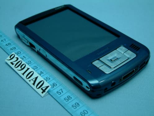
Click to zoom
Application Details
- Equipment Class
- DTS - Digital Transmission System
- Date of Grant
- Sep 18, 2003
- Application Purpose
- Original Equipment
- Date of Application
- Sep 18, 2003
- Equipment Note
- Pocket PC
- Frequency Range
- 2412.00000000 - 2462.00000000
- Company
- Compal Electronics Inc
- Country
- Taiwan
Documents & Files
Document Text
Text extracted from the exhibit documents filed with the FCC. Open a document above to read the original.
Users Manual
Toshiba Pocket PC e800/e805 User's Guide Introduction Thank you very much for your purchase of this Toshiba Pocket PC. Please be sure to read this user’s guide before using the Toshiba Pocket PC, and ensure that you are aware of correct the handling procedures. ?Please be sure to read the “Safety precautions?section in this document to learn about important safety issues. ?After reading this document, keep it in a convenient place for future reference. First Edition September 2003 ?000-2003 IA Style, Inc. All rights reserved. Copyright Information ?2003 by Toshiba Corporation. All rights reserved. Under the copyright laws, this manual cannot be reproduced in any form without the prior written permission of Toshiba. No patent liability is assumed, with respect to the use of the information contained herein. ATI?and IMAGEON?are registered trademarks of ATI Technologies, Inc. Microsoft? MS-Windows? and PowerPoint?are registered trademarks, and Windows CE?is a trademark, of Microsoft Corporation in the United States and other countries. IA Album? IA Presenter? and IA Screen Mirror?are registered trademarks of IA Style, Inc., and Information In Action?is a trademark of IA Style, Inc. The names of other actual companies, products, and brand names mentioned herein may be trade names, service marks, trademarks, or registered trademarks of their respective owners. This user’s manual and the programs in the ATI Presentation Pack are copyrighted. All rights are reserved. Reproduction, adaptation, or translation of these programs and documents without prior written permission of IA Style, Inc. is also prohibited. http://www.iastyle.com [email protected] Web sites: Product support: Toshiba Pocket PC e800/e805 User’s Guide First edition June 2003 2 Safety precautions ?Please carefully read “Safety precautions?before using the Toshiba Pocket PC e800/e805 and ensure that you are aware of correct handling procedures. ?The precautions provide essential information for the protection of the user and others from possible injury and property damage. They also provide information on the safe handling of this product. ?Please check that you fully understand the definition of the following messages (signs and graphical symbols) before reading the text, and always follow the instructions provided. NOTE Safety instructions All safety instructions must be read carefully and must be fully understood, before attempting to use your Toshiba Pocket PC. This manual contains the safety instructions that must be observed in order to avoid potential hazards that could result in personal injuries or could damage your computer. The safety instructions have been classified according to the seriousness of the Risk, as follows: Meaning Signal Word Indicates an imminently hazardous situation which, if not avoided, will result in death or serious injury. Indicates a potentially hazardous situation which, if not avoided, could result in death or serious injury. Indicates a potentially hazardous situation which, if not avoided, may result in minor or moderate injury. Indicates a potentially hazardous situation which, if not avoided, may result in property damage. Provides important information. Always request and obtain prior consent and approval of an authorized airline representative before using your Pocket PC aboard an aircraft. Always follow the instructions of the airline representative whenever using your Pocket PC aboard an aircraft, to prevent any possible interference with airborne electronic equipment. Your Pocket PC produces low levels 3 of RF energy due to the generation of digital timing pulses by its clock oscillator circuits. Your Pocket PC has been equipped with internal shielding to minimize any stray emissions of RF energy. Airlines may nevertheless prohibit the on-board use of all portable PCs (and all other portable electronic devices that could potentially emit stray RF energy), particularly during take-offs and landings, to prevent any possible interference with the reception of signals by airborne electronic navigational devices. Certain locations, such as hospitals, may restrict the use of Pocket PCs and other devices that emit low-level RF energy. Always comply was posted prohibitions of the use of RF-emitting devices, such as in hospitals. Failure to follow such directives could result in the interference with medical equipment and/or devices. Never come closer than 16 cm (6 inches) to a person with a heart pacemaker implant when using this Pocket PC in combination with a mobile cellular telephone. Failure to do so could result in interference with the function of the pacemaker. Never use a Pocket PC while driving an automobile or any other moving vehicle. Always pull out of traffic and come to a stop in a legally permissible and safe location before using your Pocket PC. Failure to do so could result in serious bodily injury in a traffic accident. Never use your Pocket PC while walking. Usage while walking could result in bodily injury caused by inattention to automobile traffic or other pedestrian hazards. Never allow metallic objects, such as staples and paper clips, to enter inside your Pocket PC. Metallic objects, such as staples and paper clips, if allowed to enter your Pocket PC, could cause the generation of excess heat or fire. Never connect terminals (metal parts) to metallic objects (such as wires). Connecting terminals to metal objects could cause excessive heat or fire. Always immediately turn the battery switch to the “off?position and disconnect the AC Adaptor from the power outlet in the event the Pocket PC emits an unusual odor or sound or generates smoke. 4 Never use or store your Pocket PC in the following locations: Anywhere it may be exposed to water, such as a bathroom or sauna; In conditions of high humidity, such as in the rain or fog; Where your Pocket PC will be exposed to high temperatures, such as near a fire or equipment that emits high temperatures; In direct sunlight; or …
Text truncated - open the document above for the full version.
Cover Letter(s)
Power of Attorney To whom it may concern: We, the undersigned Compal Electronics, Inc. hereby authorize Advance Data Technology Corporation (ADT) of Taiwan to act on our behalf in all matters relating to all processes required in the FCC Part 15C approval and any communication needed with the national authority. Any and all acts carried out by ADT on our behalf shall have the same effects as acts of our own. If you have any questions regarding the authorization, please don’t hesitate to contact us. Thank you! Sincerely yours, --------------------------------------------- Allen Chen / EMC Design Manager [email protected]
Cover Letter(s)
Federal Communications Commission Authorization and Evaluation Division Confidentiality Request FCC ID: GKRPPCE800W Pursuant to Sections 0.457 and 0.459 of the Commission’s Rules, the Applicant hereby requests confidential treatment of information accompanying this Application as outlined below: Schematics Block Diagram BOM Placement PCB Layout The above materials contain trade secrets and proprietary information not customarily released to the public. The public disclosure of these matters might be harmful to the Applicant and provide unjustified benefits to its competitors. The Applicant understands that pursuant to Rule 0.457, disclosure of this Application and all accompanying documentation will not be made before the date of the Grant for this application. Sincerely yours, --------------------------------------------- Allen Chen / EMC Design Manager [email protected]
External Photos
Page 1 CONSTRUCTION PHOTOS OF EUT Page 2
Internal Photos
Page 3 Page 4 Page 5 Page 6 Page 7 Page 8 Page 9 Page 10 Page 11 Page 12 Page 13 Page 14 Page 15 Page 16
Operational Description
FCC ID: GKRPPCE800W ADT No. 920910A05 Operational Description The transmitter of the EUT (IEEE 802.11b Wireless LAN Module) is powered by host equipment. The antenna type is inverted-F antenna with cable soldered to PCB (No connector). The other instruction, please have a look at the users manual. DSSS Information This device is Direct Sequence Spread Spectrum, the data is mixed by pseudorandom code which is an orthogonal code. The mixed data is digital modulated by BPSK and QPSK technique depends on the data rates. The CCK coding is applied for increasing the data rate, and also the processing gain will be increased. The bit rates are 1,2,5.5,11Mbps, the symbol rates are 1,1,1.375,1.375Mbps, the chip rates are always 11Mbps. So, the Chip/symbol is 11,11,8 and 8 respectively. Although is higher bit rate, the processing gain is lower than 10, but the CCK coding used in higher bit rate will provide 2.2dB coding gain.
RF Exposure Info
FCC ID: GKRPPCE800W Report No.: SA920910A05 1Issued: Sept. 15 2003 SAR TEST REPORT REPORT NO.: SA920910A05 MODEL NO.: E e800 RECEIVED: Sept. 15, 2003 TESTED: Sept. 15, 2003 APPLICANT: COMPAL ELECTRONICS INC. ADDRESS: 8F, No. 500, Juikuang Rd., Neihu, Taipei, Taiwan, R.O.C. ISSUED BY: Advance Data Technology Corporation LAB LOCATION: 47 14th Lin, Chiapau Tsun, Linko, Taipei, Taiwan, R.O.C. This test report consists of 31 pages in total except Appendix. It may be duplicated completely for legal use with the approval of the applicant. It should not be reproduced except in full, without the written approval of our laboratory. The client should not use it to claim product endorsement by any government agencies. The test results in the report only apply to the tested sample. FCC ID: GKRPPCE800W Report No.: SA920910A05 2Issued: Sept. 15 2003 Table of Contents 1.CERTIFICATION........................................................................................................................ 3 2.GENERAL INFORMATION........................................................................................................ 4 2.1GENERAL DESCRIPTION OF EUT.......................................................................................... 4 2.2GENERAL DESCRIPTION OF APPLIED STANDARDS ........................................................... 5 2.3GENERAL INOFRMATION OF THE SAR SYSTEM ................................................................. 5 2.4 GENERAL DESCRIPTION OF THE SPATIAL PEAK SAR EVALUATION................................... 9 3.DESCRIPTION OF TEST MODES AND CONFIGURATIONS................................................ 13 4.DESCRIPTION OF SUPPORT UNITS .................................................................................... 14 5.TEST RESULTS ...................................................................................................................... 15 5.1TEST PROCEDURES .............................................................................................................15 5.2MEASURED SAR RESULT ..................................................................................................... 16 5.3SAR LIMITS ............................................................................................................................. 18 5.4RECIPES FOR TISSUE SIMULATING LIQUIDS .................................................................... 18 5.5TEST EQUIPMENT FOR TISSUE PROPERTY...................................................................... 20 6.SYSTEM VALIDATION ............................................................................................................21 6.1TEST EQUIPMENT ................................................................................................................. 21 6.2TEST PROCEDURE................................................................................................................ 21 6.3VALIDATION RESULT............................................................................................................. 23 6.4SYSTEM VALIDATION UNCERTAINTIES .............................................................................. 24 7.MEASUREMENT SAR PROCEDURE UNCERTAINTIES ...................................................... 25 7.1PROBE CALIBRATION UNCERTAINTY ................................................................................. 25 7.2ISOTROPY UNCERTAINTY .................................................................................................... 25 7.3BOUNDARY EFFECT UNCERTAINTY ................................................................................... 26 7.4PROBE LINEARITY UNCERTAINTY ...................................................................................... 26 7.5READOUT ELECTRONICS UNCERTAINTY .......................................................................... 26 7.6RESPONSE TIME UNCERTAINTY ......................................................................................... 27 7.7INTEGRATION TIME UNCERTAINTY .................................................................................... 28 7.8PROBE POSITIONER MECHANICAL TOLERANCE ............................................................. 28 7.9PROBE POSITIONING............................................................................................................29 7.10 PHANTOM UNCERTAINTY..................................................................................................... 29 7.11 DASY4 UNCERTAINTY BUDGET........................................................................................... 30 8.INFORMATION ON THE TESTING LABORATORIES............................................................ 31 APPENDIX A: TEST CONFIGURATIONS AND TEST DATA APPENDIX B: ADT SAR MEASUREMENT SYSTEM APPENDIX C: PHOTOGRAPHS OF SYSTEM VALIDATION APPENDIX D: SYSTEM CERTIFICATE & CALIBRATION FCC ID: GKRPPCE800W Report No.: SA920910A05 3Issued: Sept. 15 2003 1. CERTIFICATION PRODUCT : Pocket PC MODEL NO. : e800 BRAND NAME : TOSHIBA APPLICANT : COMPAL ELECTRONICS INC. STANDARDS : 47 CFR Part 2 (Section 2.1093), FCC OET Bulletin 65, Supplement C (01-01), RSS-102 We, Advance Data Technology Corporation, hereby certify that one sample of the designation has been tested in our facility on 15 Sept. 2003. The test record, data evaluation and Equipment Under Test (EUT) configurations represented herein are true and accurate, and it was tested according to the standards listed above. This device was found to be in compliance with the Specific Absorption Rate (SAR) requirement specified in FCC part 2.1093 under General Population / Uncontrolled Exposure condition. FCC ID: GKRPPCE800W Report No.: SA920910A05 4Issued: Sept. 15 2003 2. GENERAL INFORMATION 2.1 GENERAL DESCRIPTION OF EUT PRODUCT Pocket PC MODEL NO. e800 POWER SUPPLY From host equipment CLASSIFICATION Portable device, production unit MODULATION TYPE BPSK, QPSK, CCK RADIO TECHNOLOGY DSSS TRANSFER RATE 1,2,5.5,11Mbps FR…
Text truncated - open the document above for the full version.
RF Exposure Info
Date/Time: 09/15/03 20:46:16 Test Laboratory: Advance Data Technology Pocket PC e800 Mode 1 DUT: Pocket PC ; Type: e800 ; Test Channel Frequency: 2412 MHz Communication System: 802.11b ; Frequency: 2412 MHz; Duty Cycle: 1:1; Modulation type: CCK Medium: MSL2450 (σ = 1.938 mho/m, ε r = 54.737, ρ = 1000 kg/m 3 ) ; Liquid level : 155mm Phantom section: Flat Section ; Separation distance : 0mm(The bottom of the EUT to the Phantom) Antenna type : Internal Antenna ; Air temp. : 22.0 degrees ; Liquid temp. : 21.0 degrees DASY4 Configuration: - Probe: ET3DV6 - SN1686; ConvF(4.5, 4.5, 4.5); Calibrated: 2003/6/18 - Sensor-Surface: 4mm (Mechanical Surface Detection) - Electronics: DAE3 Sn510; - Phantom: SAM Twin Phantom V4.0; Type: QD 000 P40 CA; Serial: TP-1150 - Measurement SW: DASY4, V4.1 Build 47; Postprocessing SW: SEMCAD, V1.6 Build 115 PDA Channel 1/Area Scan (71x81x1): Measurement grid: dx=15mm, dy=15mm Reference Value = 5.91 V/m Power Drift = -0.1 dB Maximum value of SAR = 0.192 mW/g PDA Channel 1/Zoon Scan (7x7x7)/Cube 0: Measurement grid: dx=5mm, dy=5mm, dz=5mm Peak SAR (extrapolated) = 0.49 W/kg SAR(1 g) = 0.192 mW/g; SAR(10 g) = 0.0772 mW/g Reference Value = 5.91 V/m Power Drift = -0.1 dB Maximum value of SAR = 0.228 mW/g Date/Time: 09/15/03 16:40:34 Test Laboratory: Advance Data Technology SystemPerformanceCheck-Body 2450-2003-09-15 DUT: Dipole 2450 MHz ; Type: D2450V2 Communication System: CW ; Frequency: 2450 MHz; Duty Cycle: 1:1; Modulation type: CW Medium: MSL2450 (σ = 1.982 mho/m, ε r = 54.574, ρ = 1000 kg/m 3 ) ; Liquid level : 155mm Phantom section: Flat Section ; Separation distance : 10mm(The feetpoint of the dipole to the Phantom) Air temp. : 22.0 degrees ; Liquid temp. : 21 degrees DASY4 Configuration: - Probe: ET3DV6 - SN1686; ConvF(4.5, 4.5, 4.5); Calibrated: 2003/6/18 - Sensor-Surface: 4mm (Mechanical Surface Detection) - Electronics: DAE3 Sn510; - Phantom: SAM Twin Phantom V4.0; Type: QD 000 P40 CA; Serial: TP-1150 - Measurement SW: DASY4, V4.1 Build 47; Postprocessing SW: SEMCAD, V1.6 Build 115 d=10mm, Pin=50mW/Area Scan (61x61x1): Measurement grid: dx=15mm, dy=15mm Reference Value = 41.3 V/m Power Drift = -0.04 dB Maximum value of SAR = 3.04 mW/g d=10mm, Pin=50mW/Zoom Scan (7x7x7) (7x7x7)/Cube 0: Measurement grid: dx=5mm, dy=5mm, dz=5mm Peak SAR (extrapolated) = 6.2 W/kg SAR(1 g) = 2.77 mW/g; SAR(10 g) = 1.24 mW/g Reference Value = 41.3 V/m Power Drift = -0.04 dB Maximum value of SAR = 3.03 mW/g APPENDIX B: ADT SAR MEASUREMENT SYSTEM APPENDIX C: PHOTOGRAPHS OF SYSTEM VALIDATION APPENDIX D: SYSTEM CERTIFICATE & CALIBRATION D1: SAM PHANTOM D2: 2450MHZ SYSTEM VALIDATION DIPOLE D3: DOSIMETRIC E-FIELD PROBE
Test Report
FCC ID: GKRPPCE800W Report No.: RF920910A051Issued: Sept. 16, 2003 FCC TEST REPORT REPORT NO.:RF920910A05 MODEL NO.:e800, e805 RECEIVED:Sept. 10, 2003 TESTED:Sept. 13 ~ 15, 2003 APPLICANT:Compal Electronics, Inc. ADDRESS:No. 581, Juikuang Rd., Neihu, Taipei (114), Taiwan, R.O.C. ISSUED BY: Advance Data Technology Corporation LAB LOCATION: 47 14th Lin, Chiapau Tsun, Linko, Taipei, Taiwan, R.O.C. This test report consists of 52 pages in total. It may be duplicated completely for legal use with the approval of the applicant. It should not be reproduced except in full, without the written approval of our laboratory. The client should not use it to claim product endorsement by CNLA, NVLAP or any government agencies. The test results in the report only apply to the tested sample. The test results in this report are traceable to the national or international standards. 0528 ILAC MRA Lab Code: 200102-0 FCC ID: GKRPPCE800W Report No.: RF920910A052Issued: Sept. 16, 2003 Table of Contents 1CERTIFICATION............................................................................................. 4 2SUMMARY OF TEST RESULTS .................................................................... 5 3GENERAL INFORMATION ............................................................................. 6 3.1GENERAL DESCRIPTION OF EUT ................................................................6 3.2DESCRIPTION OF TEST MODES ..................................................................7 3.3DESCRIPTION OF TEST MODES ..................................................................8 3.4DESCRIPTION OF SUPPORT UNITS ............................................................8 4TEST TYPES AND RESULTS ........................................................................ 9 4.1CONDUCTED EMISSION MEASUREMENT...................................................9 4.1.1 LIMITS OF CONDUCTED EMISSION MEASUREMENT ................................9 4.1.2 TEST INSTRUMENTS...................................................................................10 4.1.3 TEST PROCEDURE......................................................................................10 4.1.4 DEVIATION FROM TEST STANDARD.......................................................... 11 4.1.5 TEST SETUP................................................................................................. 11 4.1.6 EUT OPERATING CONDITIONS .................................................................. 11 4.1.7 TEST RESULTS ............................................................................................12 4.2RADIATED EMISSION MEASUREMENT......................................................18 4.2.1 LIMITS OF RADIATED EMISSION MEASUREMENT ...................................18 4.2.2 TEST INSTRUMENTS...................................................................................19 4.2.3 TEST PROCEDURE......................................................................................20 4.2.4 DEVIATION FROM TEST STANDARD..........................................................20 4.2.5 TEST SETUP.................................................................................................21 4.2.6 EUT OPERATING CONDITIONS ..................................................................21 4.2.7 TEST RESULTS ............................................................................................22 4.36dB BANDWIDTH MEASUREMENT .............................................................30 4.3.1 LIMITS OF 6dB BANDWIDTH MEASUREMENT..........................................30 4.3.2 TEST INSTRUMENTS...................................................................................30 4.3.3 TEST PROCEDURE......................................................................................30 4.3.4 DEVIATION FROM TEST STANDARD..........................................................30 4.3.5 TEST SETUP.................................................................................................31 4.3.6 EUT OPERATING CONDITION.....................................................................31 4.3.7 TEST RESULTS ............................................................................................32 4.4MAXIMUM PEAK OUTPUT POWER.............................................................36 4.4.1 LIMITS OF MAXIMUM PEAK OUTPUT POWER MEASUREMENT .............36 4.4.2 TEST INSTRUMENTS...................................................................................36 4.4.3 TEST PROCEDURE......................................................................................36 4.4.4 DEVIATION FROM TEST STANDARD..........................................................36 4.4.5 TEST SETUP.................................................................................................37 4.4.6 EUT OPERATING CONDITION.....................................................................37 4.4.7 TEST RESULTS ............................................................................................38 4.5POWER SPECTRAL DENSITY MEASUREMENT ........................................39 4.5.1 LIMITS OF POWER SPECTRAL DENSITY MEASUREMENT......................39 FCC ID: GKRPPCE800W Report No.: RF920910A053Issued: Sept. 16, 2003 4.5.2 TEST INSTRUMENTS...................................................................................39 4.5.3 TEST PROCEDURE......................................................................................39 4.5.4 DEVIATION FROM TEST STANDARD..........................................................39 4.5.5 TEST SETUP.................................................................................................40 4.5.6 EUT OPERATING CONDITION.....................................................................40 4.5.7 TEST RESULTS ............................................................................................41 4.6BAND EDGES MEASUREMENT ..................................................................45 4.…
Text truncated - open the document above for the full version.
Test Setup Photos
FCC ID: GKRPPCE800W Report No.: RF920910A0550Issued: Sept. 16, 2003 5 PHOTOGRAPHS OF THE TEST CONFIGURATION CONDUCTED EMISSION TEST FCC ID: GKRPPCE800W Report No.: RF920910A0551Issued: Sept. 16, 2003 RADIATED EMISSION TEST
Contact Information
Applicant
Joyce Ting(Senior RF Regulatory Compliance Engineer)
Technical Contact
Advance Data Technology CorporationEllis Wu
[email protected]+886 3 327 0910
13-1, Lane19, WenShan 3rd., St. · Taoyuan · Taiwan
Non-Technical Contact
Advance Data Technology CorporationMrs. Yemmy Soong
[email protected]+886 2 2605 2180
Test Firm
Bureau Veritas CPS (H.K.) Ltd. Taoyuan BranchRichard Chen
Technical Specifications
| # | Rule Parts | Frequency Range | Power Output |
|---|---|---|---|
| 1 | 15C | 2.41 GHz - 2.46 GHz | 33.00 mW |
Other Applications from Compal Electronics Inc
GKRRXLN4N
May 26, 2026LGA Module
Equipment Class
CBE - Citizens Band End User DevicesGKRCMMG3L
May 08, 20265G Module
Equipment Class
CBE - Citizens Band End User DevicesGKRRMMG4
Jan 23, 20265G Module
Equipment Class
CBE - Citizens Band End User DevicesGKRRXLN3
Dec 08, 2024LGA Module
Equipment Class
CBE - Citizens Band End User DevicesGKRRMMT1
Aug 14, 2024NTN miniPCIE module
Equipment Class
TNB - Licensed Non-Broadcast Station Transmitter