GLE2800027R/C Toy Transmitter
Suncon Toys Industry Ltd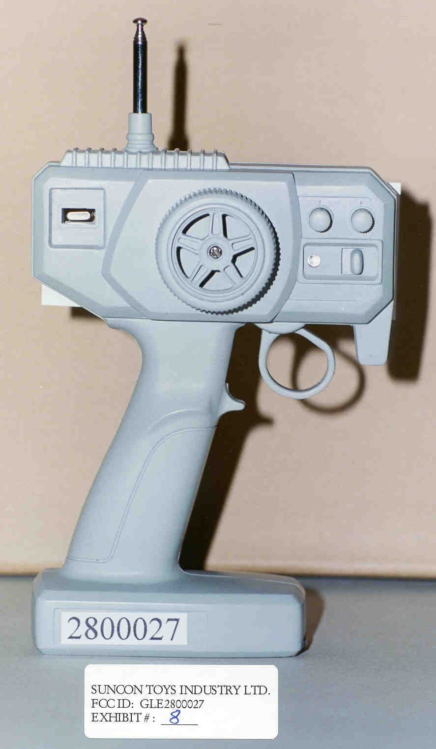
Click to zoom
Application Details
- Equipment Class
- DXX - Part 15 Low Power Communication Device Transmitter
- Date of Grant
- Aug 18, 1999
- Application Purpose
- Original Equipment
- Date of Application
- Jun 30, 1999
- Equipment Note
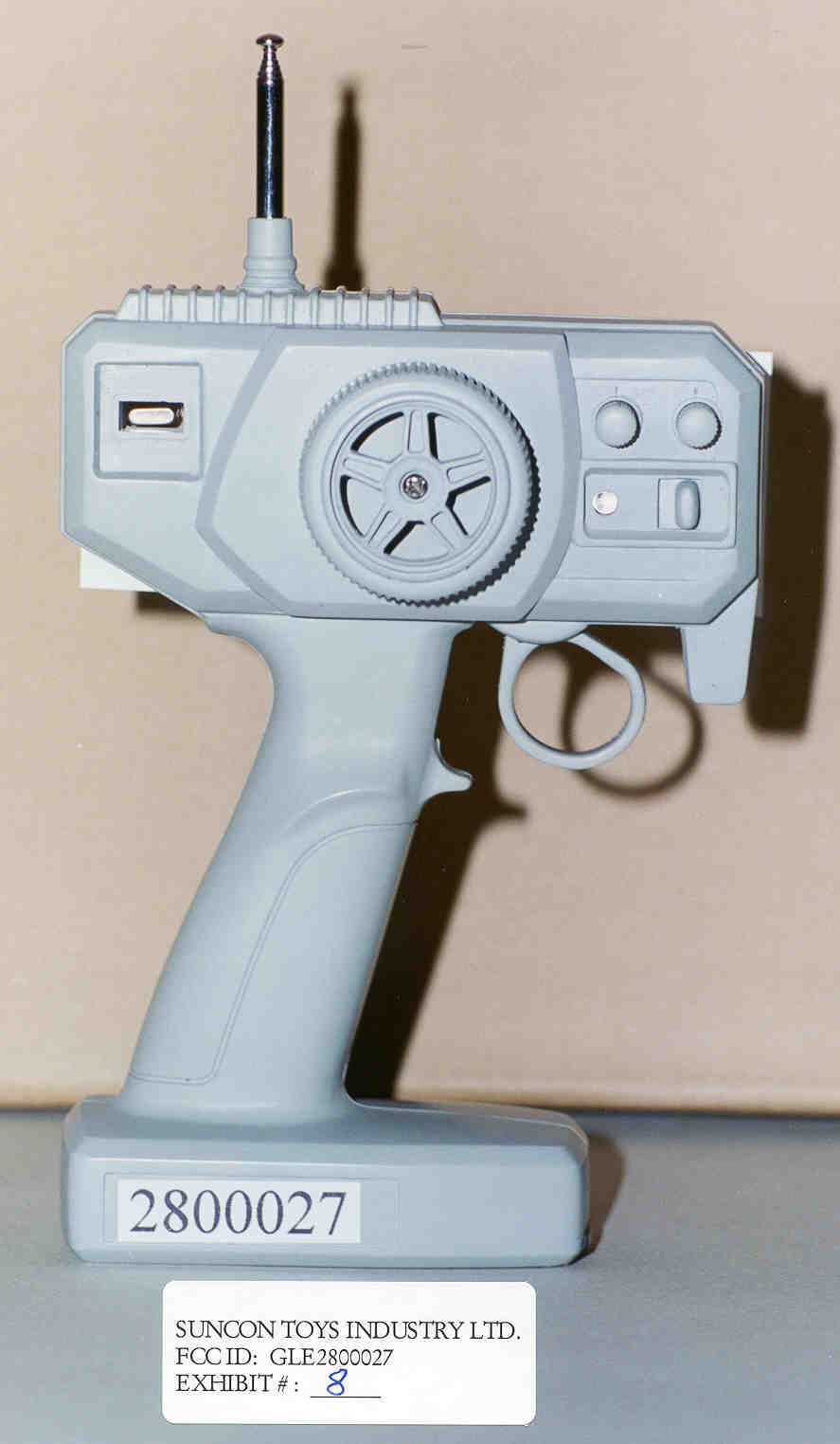
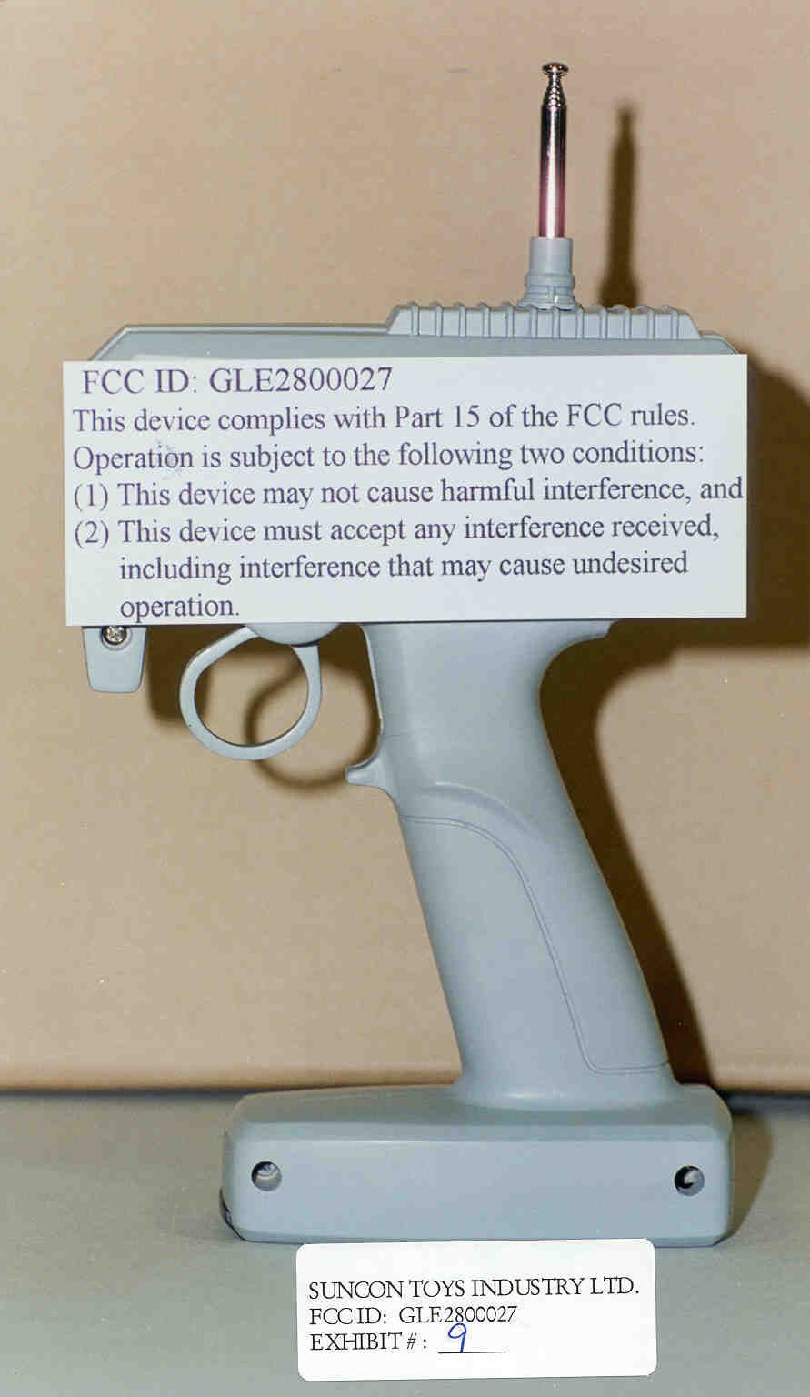
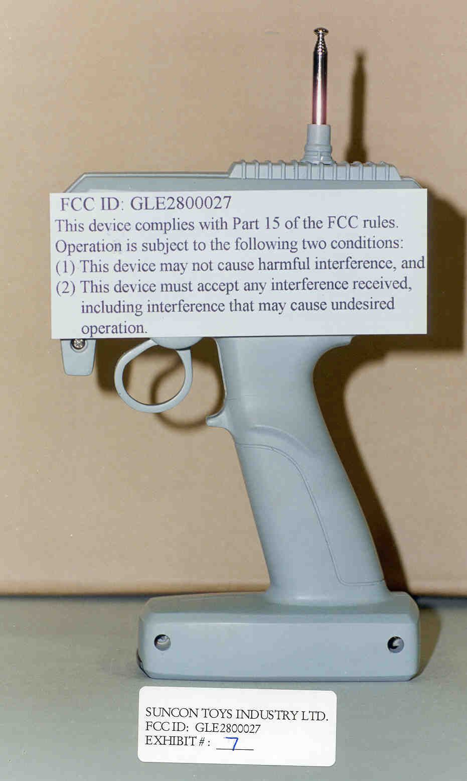
- R/C Toy Transmitter
- Frequency Range
- 26.96000000 - 27.28000000
- Company
- Suncon Toys Industry Ltd
- Country
- Hong Kong
Documents & Files
Document Text
Text extracted from the exhibit documents filed with the FCC. Open a document above to read the original.
Test Report
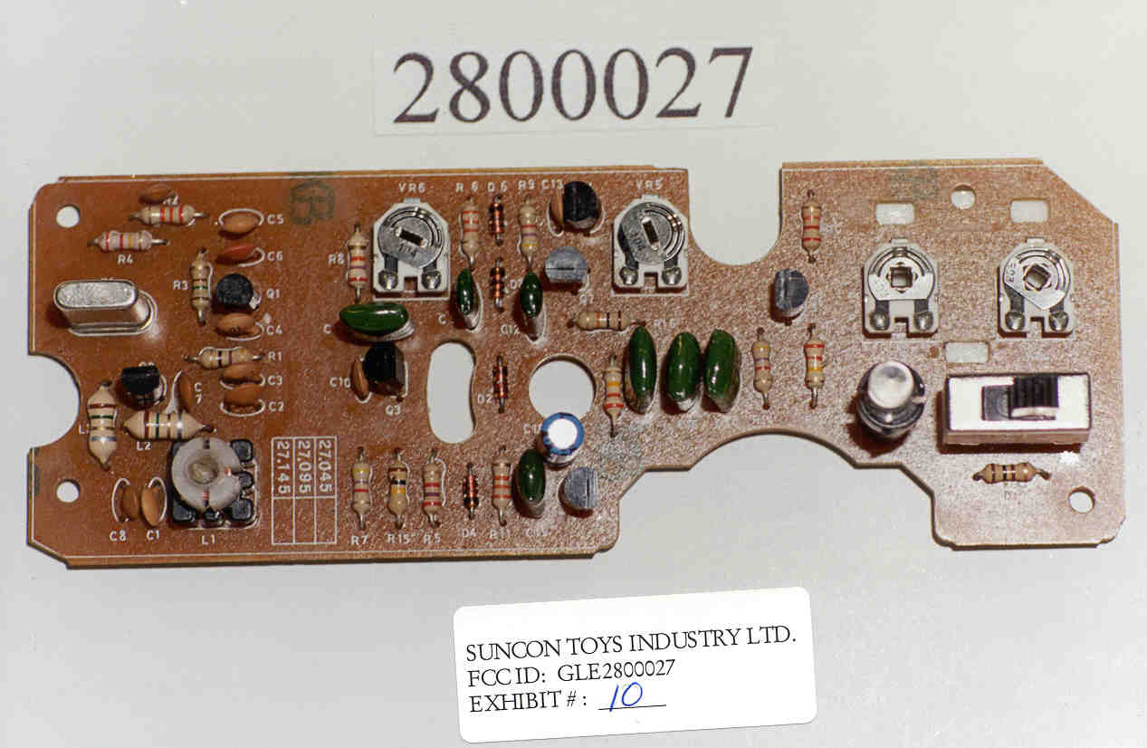
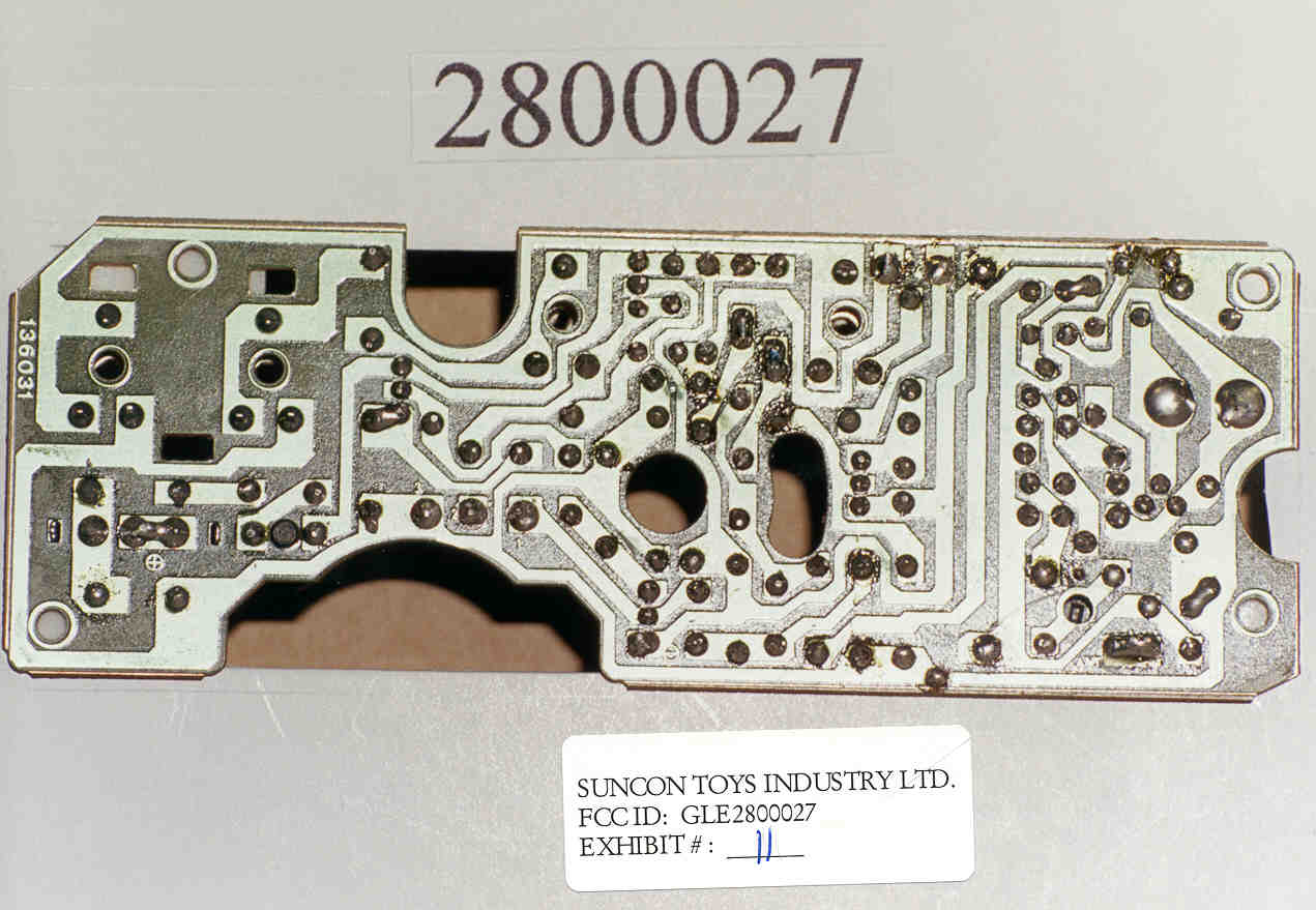
TABLE OF CONTENTS APPLICANT: SUNCON TOYS INDUSTRY LTD. FCC ID: GLE2800027 TEST REPORT CONTAINING: PAGE 1......TEST PROCEDURE PAGE 2......TEST PROCEDURE AND CIRCUIT DESCRIPTION PAGE 3......RADIATION INTERFERENCE TEST DATA PAGE 4......OCCUPIED BANDWIDTH TEST DATA EXHIBITS CONTAINING: EXHIBIT 1............POWER OF ATTORNEY LETTER EXHIBIT 2............LETTER CONFIRMING CHANGES EXHIBIT 3............BLOCK DIAGRAM EXHIBIT 4............SCHEMATIC EXHIBIT 5A-5B........PARTS LIST EXHIBIT 6A-6E........INSTRUCTION MANUAL EXHIBIT 7............FCC ID LABEL SAMPLE AND LOCATION EXHIBIT 8............EXTERNAL PHOTO - FRONT SIDE EXHIBIT 9............EXTERNAL PHOTO - BACK SIDE EXHIBIT 10...........INTERNAL PHOTO - COMPONENT SIDE EXHIBIT 11...........INTERNAL PHOTO - COPPER SIDE EXHIBIT 12...........OCCUPIED BANDWIDTH PLOT - MODULATED APPLICANT: SUNCON TOYS INDUSTRY LTD. FCC ID: GLE2800027 REPORT #: F:\CUS\S\SUNCON\SUN275H9.RPT PAGE: TABLE OF CONTENTS LIST APPLICANT: SUNCON TOYS INDUSTRY LTD. FCC ID: GLE2800027 TEST EQUIPMENT LIST 1. Spectrum Analyzer: Hewlett Packard 8566B - Opt 462, w/ preselector 85685A, & Quasi-Peak Adapter HP 8565OA, & HP 8449B - OPT H02 Cal. 6/26/98 2. Signal Generator, Hewlett Packard 8640B, cal. 10/1/98 3. Signal Generator, HP 8614A Serial No.2015A07428 cal. 5/27/99 3. Eaton Biconnical Antenna Model 94455-1 20-200 MHz Serial No. 0997 Cal. 10/30/98 4. Electro-Metric Dipole Kit, 20-1000 MHz, Model TDA-30 10/31/98 5. Electro-Metric Horn 1-18 GHz, Model RGA-180, Cal. 10/30/98 6. Electro-Metric Antennas Model TDA-30/1-4,Cal. 10/15/98 7. Electro-Metric Line Impedance Stabilization Network Model No. EM-7821, Serial No. 101; 100KHz-30MHz 50uH. Cal.11/19/98 8. Electro-Metric Line Impedance Stabilization Network Model No. EM-7820, Serial No. 2682; 10KHz-30MHz 50uH. Cal. 11/19/98 9. Special low loss cable was used above 1 GHz 10. Tenney Temperature Chamber TEST PROCEDURE GENERAL: This report shall NOT be reproduced except in full without the written approval of TIMCO ENGINEERING, INC. RADIATION INTERFERENCE: The test procedure used was ANSI STANDARD C63.4-1992 using a HEWLETT PACKARD spectrum analyzer with a prese- lector. The bandwidth of the spectrum analyzer was 100 kHz with an appropriate sweep speed. The analyzer was calibrated in dB above a microvolt at the output of the antenna. The resolution bandwidth was 100KHz and the video bandwidth was 300KHz. The ambient temperature of the UUT was with a humidity of . FORMULA OF CONVERSION FACTORS: The Field Strength at 3m was estab- lished by adding the meter reading of the spectrum analyzer (which is set to read in units of dBuV) to the antenna correction factor sup- plied by the antenna manufacturer. The antenna correction factors are stated in terms of dB. The gain of the Preselector was accounted for in the Spectrum Analyzer Meter Reading. Example: Freq (MHz) METER READING + ACF = FS 33 20 dBuV + 10.36 dB = 30.36 dBuV/m @ 3m POWER LINE CONDUCTED INTERFERENCE: The procedure used was ANSI STAN- DARD C63.4-1992 using a 50uH LISN. Both lines were observed. The bandwidth of the spectrum analyzer was 10kHz with an appro- priate sweep speed. The ambient temperature of the UUT was with a humidity of . FCC ID: GLE2800027 REPORT #: F:\CUS\S\SUNCON\SUN275H9.RPT PAGE #: 1 TEST PROCEDURES CONTINUED APPLICANT: SUNCON TOYS INDUSTRY LTD. FCC ID: GLE2800027 ANSI STANDARD C63.4-1992 10.1.7 MEASUREMENT PROCEDURES: The unit under test was placed on a table 80 cm high and with dimensions of 1m by 1.5m. The table used for radiated measurements is capable of continuous rotation. When an emission was found, the table was rotated to produce the maximum signal strength. At this point, the antenna was raised and lowered from 1m to 4m. The antenna was placed in both the horizontal and vertical planes. The situation was similar for the conducted measurement except that the table did not rotate. The EUT was setup as described in ANSIC63.4-1992 with the EUT 40 cm from the vertical ground wall. CIRCUIT DESCRIPTION: In the transmit mode the momentary switches SW-L, SW-R, SW-B, & SW-F provide input to the encoder intergrated circuit U1. The output of U1 modulated the RF oscillator Q1 by varing the emitter current of that stage. The RF frequency is determined by the crystal Y1. The output of Q1 is coupled through C10 to the base of the RF amplifier Q2. From Q2 the signal is fed into the tuned circuit made up of L3/C5 & then to the low pass filter made up of C7/L2/C8 and is then fed to the antenna. ANTENNA_AND_GROUND_CIRCUITRY This unit makes use of a short, antenna. The antenna is induc- tively coupled. The antenna is self contained, no provision is made for an external antenna. This unit is powered from a 9.0V battery. No ground connection is provided. The unit relies on the ground tract of the printed circuit board. APPLICANT: SUNCON TOYS INDUSTRY LTD. FCC ID: GLE2800027 REPORT #: F:\CUS\S\SUNCON\SUN275H9.RPT PAGE #: 2 APPLICANT: SUNCON TOYS INDUSTRY LTD. FCC ID: GLE2800027 NAME OF TEST: RADIATION INTERFERENCE RULES PART NO.: 15.227 REQUIREMENTS: CARRIER FREQUENCY WILL NOT EXCEED 80 dBuV/m AT 3M. OUT-OF-BAND EMISSIONS SHALL NOT EXCEED: 30 - 88 MHz 40.0 dBuV/M MEASURED AT 3 METERS 88 - 216 MHz 43.5 dBuV/M 216 - 960 MHz 46.0 dBuV/M ABOVE 960 MHz 54.0 dBuV/M TEST DATA: PEAK EMISSION METER READING COAX ANTENNA FIELD FREQUENCY AT 3 METERS LOSS CORRECTION STRENGTH MARGIN ANT. MHz dBuV dB FACTOR dB dBuV/m@3m dB POL. 27.09 68.00 0.20 11.78 79.98 0.02 V SAMPLE CALCULATION: FSdBuV/m = MR(dBuV) + ACFdB. TEST PROCEDURE: The procedure used was ANSI STANDARD C63.4-1992. The spectrum was scanned from 30 MHz to 1000 MHz. When an emission was found, the table was rotated to produce the maximum signal strength. The antenna was placed in both the horizontal and vertical planes and the worse case emissions were reported. The UUT was tested in 3 orthogonal planes. TEST RESULTS: THE UNIT DOES MEET THE FCC REQUIREMENTS. PERFORMED BY:___________________________________ DATE: JUNE 30, 1999 APPLICANT:…
Text truncated - open the document above for the full version.
Contact Information
Applicant
Garry Feung
852 2352-3268Fax: 852 2352-3267
Technical Contact
Timco Engineering Inc.S S Sanders
[email protected]888-472-2424
P O Box 370 · Newberry, Florida · United States
Non-Technical Contact
Timco Engineering Inc.Sharon A Hoffman
[email protected]888-472-2424
Test Firm
Timco Engineering, Inc.Sid Sanders
Technical Specifications
| # | Rule Parts | Frequency Range | Power Output |
|---|---|---|---|
| 1 | 15C | 26.96 MHz - 27.28 MHz | - |
Other Applications from Suncon Toys Industry Ltd
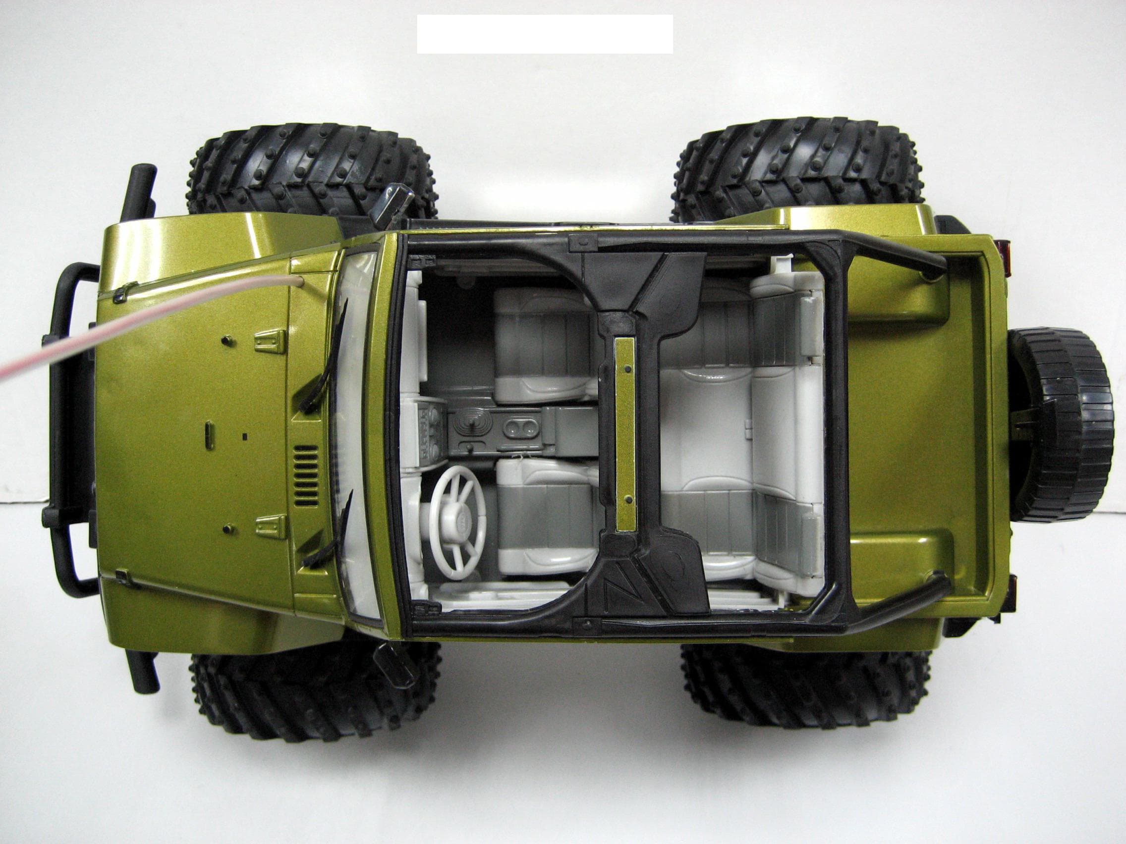
GLE136227R
Mar 26, 200849.82-49.90 MHZ WIRELESS R/C TOY-RX
Equipment Class
CYY - Communications Receiver used w/Pt 15 Transmitter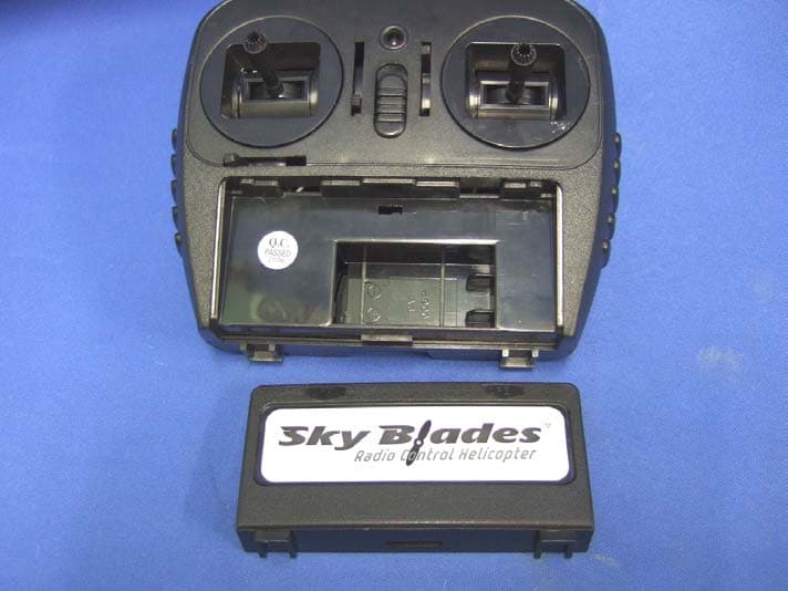
GLE8251
Jul 26, 2007RC Helicopter
Equipment Class
DXX - Part 15 Low Power Communication Device Transmitter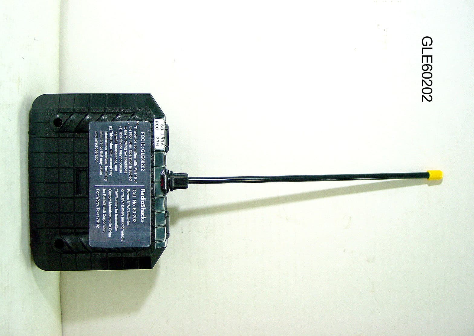
GLE60202
Jun 17, 2007Wireless Remote Control Toy Transmitter
Equipment Class
DXX - Part 15 Low Power Communication Device Transmitter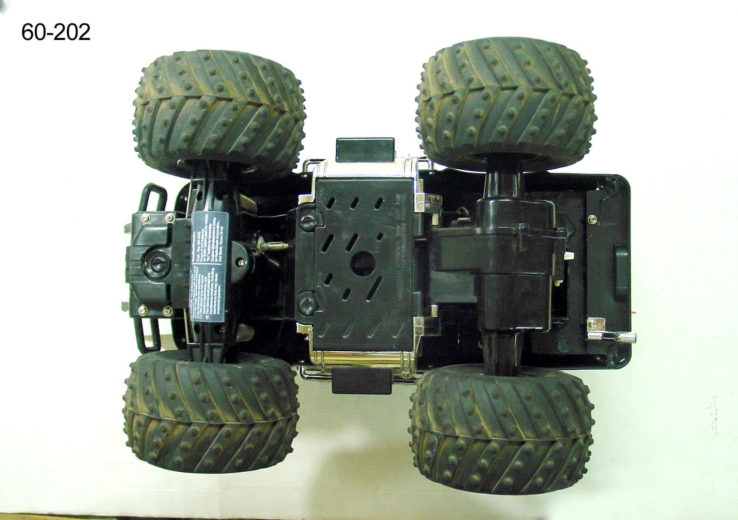
GLE60202R
Jun 17, 2007Wireless Remote Control Toy Receiver
Equipment Class
CYY - Communications Receiver used w/Pt 15 Transmitter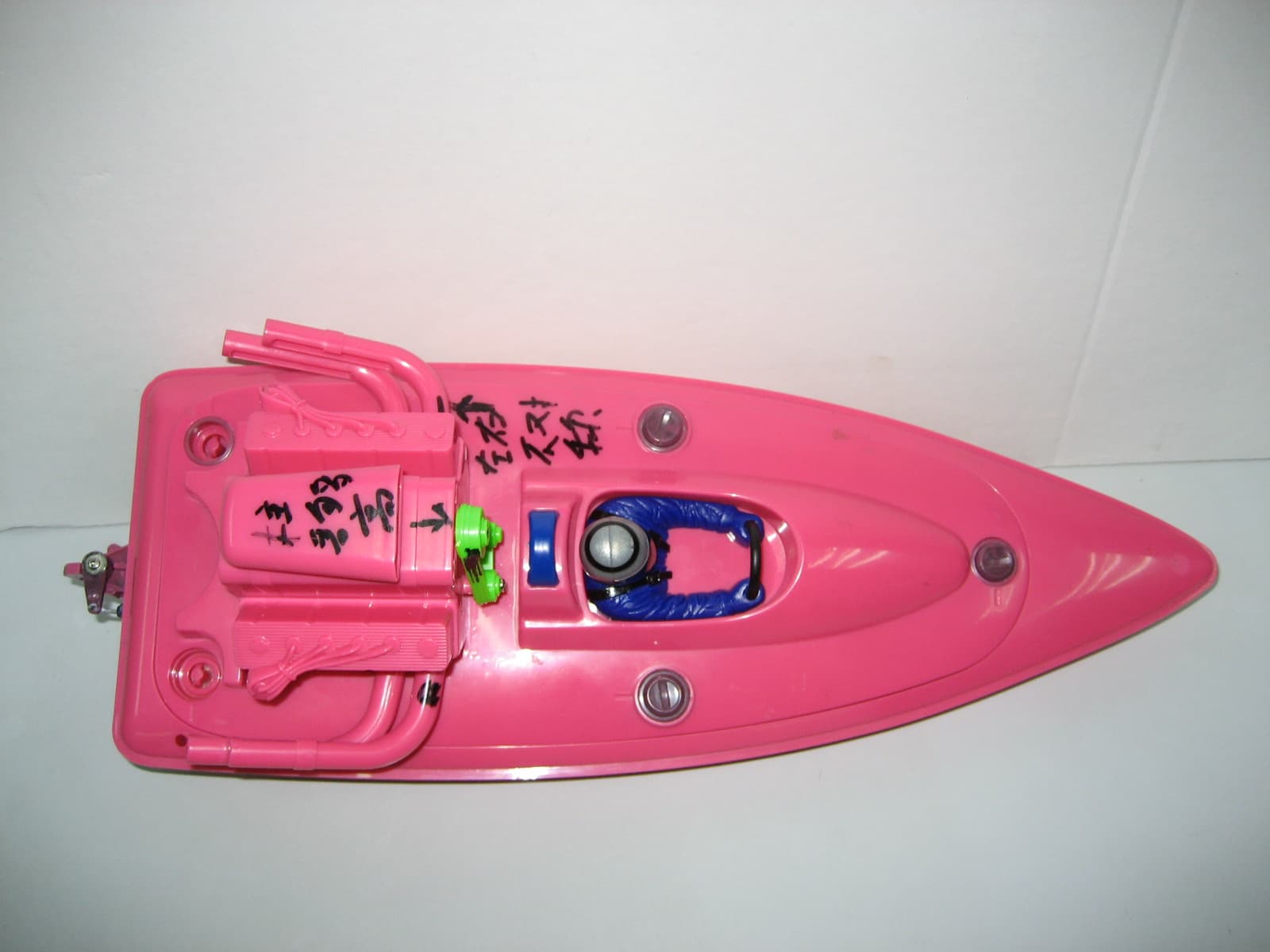
GLE60153R
Jan 15, 2007WIRELESS REMOTE CONTROL RECEIVER
Equipment Class
CRR - Superregenerative Receiver