GLE60438449.82 - 49.90 MHz Wireless R/C Toy - RX
Suncon Toys Industry Ltd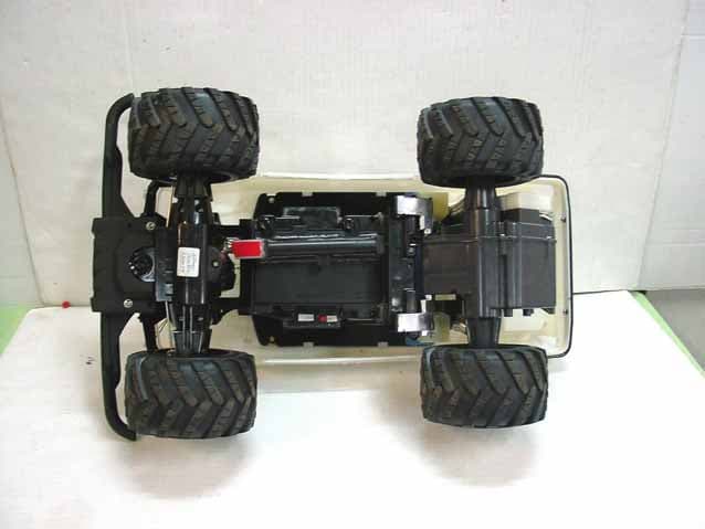
Click to zoom
Application Details
- Equipment Class
- CRR - Superregenerative Receiver
- Date of Grant
- Jul 18, 2004
- Application Purpose
- Original Equipment
- Date of Application
- Jul 18, 2004
- Equipment Note
- 49.82 - 49.90 MHz Wireless R/C Toy - RX
- Frequency Range
- 49.82000000 - 49.90000000
- Company
- Suncon Toys Industry Ltd
- Country
- Hong Kong
Documents & Files
Document Text
Text extracted from the exhibit documents filed with the FCC. Open a document above to read the original.
Users Manual
Chevrolet Avalanche transmitter user’s guide Thank you for purchasing your RadioShack Petersen’s 4-Wheel & Off-Road Chevrolet Avalanche. Scaled to 1:13 the size of a real Chevy Avalanche, it can reach speeds of up to 600 feet per minute and climb 40 degree inclines. This truck is perfect for children ages 8 and up. 1. Extend the transmitter’s antenna to its full length. 2. Turn the transmitter and the truck on. The headlights should turn on. 3. Pull the speed control trigger toward the handle to move forward. Pull all the way in for turbo speed. 4. Push the trigger away from the handle to move backward. 5. Release to stop.6. Use the steering control wheel to turn left and right. 7. Release the wheel to drive straight.8. When you fi nish driving the vehicle, turn it off. You can use the gear switch on the transmitter to select high or low gear. Raise it up for high gear to drive on rough surfaces, the indicator lights red. Put it down for low gear to drive on rough surfaces, the indicator light green. Please read this user’s guide before installing, setting up and using your new product www.radioshack.com 60-4384 Petersen’s 4-wheel & off-road Chevrolet Avalanche To power your truck, you will need one 9V battery for the transmitter and one 9.6V battery pack for the truck. Neither of these batteries is included, but both are available at your local RadioShack or online at www.radioshack.com.in the transmitter1. Remove the cover.2. Put the 9 volt battery in the compartment as indicated by the polarity symbols (+ and -). Replace the cover. When the transmitter’s range decreases, replace its battery. NOTE in the truck1. Remove the battery compartment cover. Replace when fi nished. 2. Attach the battery pack’s connector to the truck’s connector. It fi ts only one way. 3. Place the battery pack in its compartment. Replace the cover and secure it. When the truck’s operation becomes erratic, replace the batteries. NOTE NOTE wheel alignmentIf the car does not drive in a straight line when you release the right control lever, adjust the wheel alignment control on the bottom of the car. Turn the control toward L if the car is pulling to the right or toward R if the car is pulling to the left. Battery compartment cover Battery connector 9V Battery 9.6V Battery Pack Alignment control ON/OFF switch Antenna Steering control wheel Speed control trigger Front Wheels Gear Switch ©2004 RadioShack Corporation.All rights reserved. RadioShack and RadioShack.com are trademarks used by RadioShack Corporation. 60-4384 06A04 printed in China This product is warranted by RadioShack against manufacturing defects in material and workmanship under normal use for ninety (90) days from the date of purchase from RadioShack company-owned stores and authorized RadioShack franchisees and dealers. For complete warranty details and exclusions, check with your local RadioShack store.RadioShack Customer Relations200 Taylor Street, 6th Floor, Fort Worth, TX 76102 04/04 This equipment has been tested and found to comply with the limits for a Class B digital device, pursuant to Part 15 of the FCC Rules. These limits are designed to provide reasonable protection against harmful interference in a residential installation. This equipment generates, uses, and can radiate radio frequency energy and, if not installed and used in accordance with the instructions, may cause harmful interference to radio communications. However, there is no guarantee that interference will not occur in a particular installation. If this equipment does cause harmful interference to radio or television reception, which can be determined by turning the equipment off and on, the user is encouraged to try to correct the interference by one or more of the following measures: • Reorient or relocate the receiving antenna.• Increase the separation between the equipment and receiver. • Connect the equipment into an outlet on a circuit different from that to which the receiver is connected. Consult your local RadioShack store or an experienced radio/TV technician for help.If you cannot eliminate the interference, the FCC requires that you stop using your phone. Changes or modifi cations not expressly approved by RadioShack may cause interference and void the user’s authority to operate the equipment.This device complies with Part 15 of the FCC Rules. Operation is subject to the following two conditions: (1) This device may not cause harmful interference, and (2) This device must accept any interference received, including interference that may cause undesired operation. • Driving your truck for long periods of time can generate a high heat level, which causes wear and tear on the motor. To help keep heat levels down, when your vehicle’s battery power dies, let it cool for at least 10 minutes before installing new batteries. • Do not touch the motor immediately after using the truck, as it may become hot during use. • If your truck’s motor runs, but does not respond to the transmitter, move closer to the vehicle and try again. • If someone uses a CB nearby, it might interfere with the control of your truck. If this happens, move the vehicle away from the CB. • You cannot operate your truck near devices with transmitters that use the same frequency as your vehicle (27 MHz or 49 MHz). Check the box to see which frequency you have. • If the truck moves slowly, or not at all, and you have installed new batteries, check the wheel mechanism for lint, dust, hair or thread. • When the transmitter’s range decreases, replace its battery. • The truck might make a popping or grinding noise when you slide the gear control switch. This is normal. • Dispose of old batteries promptly and properly. Do not burn or bury batteries. • Use only fresh batteries of the required size and recommended type. • Do not use batteries of different types capacities, or chemistry. • If you do not plan to use the toy for several days, remove the batteries. Batteries can leak chemicals that can damage el…
Text truncated - open the document above for the full version.
Test Report
THRU Lab & Engineering. RM1105,11FL, ACE TECHNO TOWER 197-22,GURO-DONG GURO-GU, SEOUL KOREA 81221095059F81221095056 email [email protected] APPLICANT: SUNCON TOYS INDUSTRY LTD. FCC ID: GLE604384 REPORT :THRU-407012 COVER SHEET Test Report Product Name: 49.82-49.90 MHz Wireless R/C Toy - RX FCC ID: GLE604384 Applicant: SUNCON TOYS INDUSTRY LTD. 11/F, KAI TAK FACTORY BUILDING 99 KING FUK STREET SANPOKONG, KOWLOON, HONG KONG Date Receipt: 07/05/2004 Date Tested: 07/09/2004 THRU Lab & Engineering. RM1105,11FL, ACE TECHNO TOWER 197-22,GURO-DONG GURO-GU , SEOUL KOREA T81221095059F81221095056 email [email protected] APPLICANT: SUNCON TOYS INDUSTRY LTD. FCC ID: GLE604384 REPORT :THRU-407012 TABLE OF CONTENTS TABLE OF CONTENTS LIST APPLICANT: SUNCON TOYS INDUSTRY LTD. FCC ID: GLE604384 TEST REPORT CONTAINING: PAGE 1...............TEST EQUIPMENT LIST PAGE 2...............TEST PROCEDURES PAGE 3...............RADIATION INTERFERENCE TEST DATA EXHIBITS CONTAINING: EXHIBIT 1............BLOCK DIAGRAM EXHIBIT 2............SCHEMATIC EXHIBIT 3............INSTRUCTION MANUAL EXHIBIT 4............SAMPLE OF FCC ID LABEL EXHIBIT 5............LOCATION OF FCC ID LABEL EXHIBIT 6............EXTERNAL PHOTO - FRONT SIDE EXHIBIT 7............EXTERNAL PHOTO - BACK SIDE EXHIBIT 8............INTERNAL PHOTO - COMPONENT SIDE EXHIBIT 9............INTERNAL PHOTO - COPPER SIDE EXHIBIT 10...........CIRCUIT DESCRIPTION EXHIBIT 11...........TEST SET UP PHOTO THRU Lab & Engineering. RM1105,11FL, ACE TECHNO TOWER 197-22,GURO-DONG GURO-GU , SEOUL KOREA T81221095059F81221095056 email [email protected] APPLICANT: SUNCON TOYS INDUSTRY LTD. FCC ID: GLE604384 REPORT :THRU-407012 Page 1 of 3 APPLICANT: SUNCON TOYS INDUSTRY LTD. FCC ID: GLE604384 TEST EQUIPMENT LIST DEVICE MODEL MFGR SERNO DUE.CAL EMI Test Receiver ESVS 10 Rohde & Schwarz 830489/001 2005.04.07. Spectrum Analyzer 8566B Hewlett Packard 2311A02394 2005.04.07. Spectrum Display 85662A Hewlett Packard 2542A12429 2005.04.07. Quasi-Peak Adapter 85650A Hewlett Packard 2521A00887 2005.04.07. RF Preselector 85685A Hewlett Packard 2648A00504 2005.04.07. Pre-Amplifier 8449B Hewlett Packard 3008A00375 2005.04.07. Pre-Amplifier 8447F Hewlett Packard 3113A05367 2005.04.07. Spectrum Monitor EZM Rohde & Schwarz 862304/007 2005.04.07. Bico-Antenna 94455-1 Eaton 977 2005.03.17. Log-Periodic Antenna 3146 EMCO 2051 2005.03.17. Dipole Antenna TDA25/1/2 Electro Metrics 176/200/200 2005.03.17. Horn Antenna SAS-571 A.H Systems 414 2005.03.17. Spectrum Analyzer R3261C Advantest 71720189 2005.04.07. LISN KNW-242 Kyoritsu 8-923-2 2004.07.17. LISN 8012-50-R- 24 Solar 8379121 2004.07.17. Loop Ant 6507 EMCO 1435 2004.10.06. Signal Generator SMS Rohde & Schwarz 872165/100 2005.04.07. Modulation Analyzer 8901B Hewlett Packard 3438A05094 2005.04.07. Frequency Counter CMC251 Tektronic CMC-251TW52489 2005.04.07. THRU Lab & Engineering. RM1105,11FL, ACE TECHNO TOWER 197-22,GURO-DONG GURO-GU , SEOUL KOREA T81221095059F81221095056 email [email protected] APPLICANT: SUNCON TOYS INDUSTRY LTD. FCC ID: GLE604384 REPORT :THRU-407012 Page 2 of 3 TEST PROCEDURE GENERAL: This report shall NOT be reproduced except in full without the written approval of ThruLab & Engineering. RADIATION INTERFERENCE: The test procedure used was ANSI STANDARD C63.4-1992 using a HEWLETT PACKARD spectrum analyzer with a preselector. The bandwidth of the spectrum analyzer was 100 kHZ with an appropriate sweep speed. The analyzer was calibrated in dB above a microvolt at the output of the antenna. The resolution bandwidth was 100KHZ and the video bandwidth was 300KHZ. The ambient temperature of the UUT was 27ºC with a humidity of 61%. FORMULA OF CONVERSION FACTORS: The Field Strength at 3m was established by adding the meter reading of the spectrum analyzer (which is set to read in units of dBuV) to the antenna correction factor supplied by the antenna manufacturer. The antenna correction factors are stated in terms of dB. The gain of the Preselector was accounted for in the Spectrum Analyzer Meter Reading. Example: Freq (MHz) METER READING + ACF = FS 33 20 dBuV + 10.36 dB = 30.36 dBuV/m @ 3m ANSI STANDARD C63.4-1992 10.1.7 MEASUREMENT PROCEDURES: The unit under test was placed on a table 80 cm high and with dimensions of 1m by 1.5m. The table used for radiated measurements is capable of continuous rotation. When an emission was found, the table was rotated to produce the maximum signal strength. At this point, the antenna was raised and lowered from 1m to 4m. The antenna was placed in both the horizontal and vertical planes. ANSI STANDARD C63.4-1992 12.1.1.1 SUPERREGENERATIVE RECEIVER: A signal Generator was set to the unit under test operating frequency. An un- Modulated continuous wave (CW) signal was radiated at the super regenerative receiver operating frequency to cohere the characteristic broadband emissions from the receiver. The situation was similar for the conducted measurement except that the table did not rotate. The EUT was setup as described in ANSIC63.4-1992 with the EUT 40 cm from the vertical ground wall. Not Applicable, battery operated. THRU Lab & Engineering. RM1105,11FL, ACE TECHNO TOWER 197-22,GURO-DONG GURO-GU , SEOUL KOREA T81221095059F81221095056 email [email protected] APPLICANT: SUNCON TOYS INDUSTRY LTD. FCC ID: GLE604384 REPORT :THRU-407012 Page 3 of 3 APPLICANT: SUNCON TOYS INDUSTRY LTD. FCC ID: GLE604384 NAME OF TEST: RADIATION INTERFERENCE RULES PART NO.: 15.109 REQUIREMENTS: 30 to 88 MHz: 40.0 dBuV/M @ 3 METERS 88 to 216 MHz: 43.5 dBuV/M 216 to 960 MHz: 46.0 dBuV/M ABOVE 960 MHz: 54.0 dBuV/M TEST RESULTS: A search was made of the spectrum from 30 to 1000MHz and the measurements indicate that the unit DOES meet the FCC requirements. TEST DATA: No Emission Frequency (MHz) Meter Reading dBuV Ant. Polaritry Correction Factor dB Cable Loss dB Field Strength (dBuv/m) Margin (dBuv) Limit (dBuv/m) 1 39.76 12.4 V 12.8 0.8 26.0 -14.0 40.0 2 43.84 10.8 V 12.1 0.9 23.8 -16.2 40.0 3 79.25 14.8 V 7.9 1.3 24.0 -16.…
Text truncated - open the document above for the full version.
Test Setup Photos
THRU Lab & Engineering. RM1105,11FL, ACE TECHNO TOWER 197-22,GURO-DONG GURO-GU , SEOUL KOREA T81221095059F81221095056 email [email protected] APPLICANT:SUNCON TOYS INDUSTRY LTD. FCC ID: GLE604384 REPORT :THRU-407012 THRU Lab & Engineering. RM1105,11FL, ACE TECHNO TOWER 197-22,GURO-DONG GURO-GU , SEOUL KOREA T81221095059F81221095056 email [email protected] APPLICANT:SUNCON TOYS INDUSTRY LTD. FCC ID: GLE604384 REPORT :THRU-407012 THRU Lab & Engineering. RM1105,11FL, ACE TECHNO TOWER 197-22,GURO-DONG GURO-GU , SEOUL KOREA T81221095059F81221095056 email [email protected] APPLICANT:SUNCON TOYS INDUSTRY LTD. FCC ID: GLE604384 REPORT :THRU-407012
Contact Information
Applicant
Garry Feung
852 2352-3268Fax: 852 2352-3267
Test Firm
Thru Lab & EngineeringK. Kang
Technical Specifications
| # | Rule Parts | Frequency Range | Power Output |
|---|---|---|---|
| 1 | 15B | 49.82 MHz - 49.9 MHz | - |
Other Applications from Suncon Toys Industry Ltd
GLE136227R
Mar 26, 200849.82-49.90 MHZ WIRELESS R/C TOY-RX
Equipment Class
CYY - Communications Receiver used w/Pt 15 Transmitter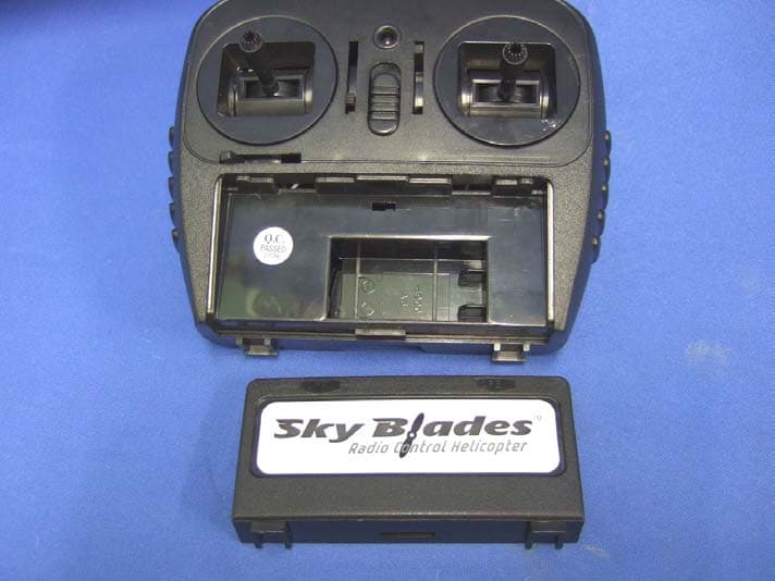
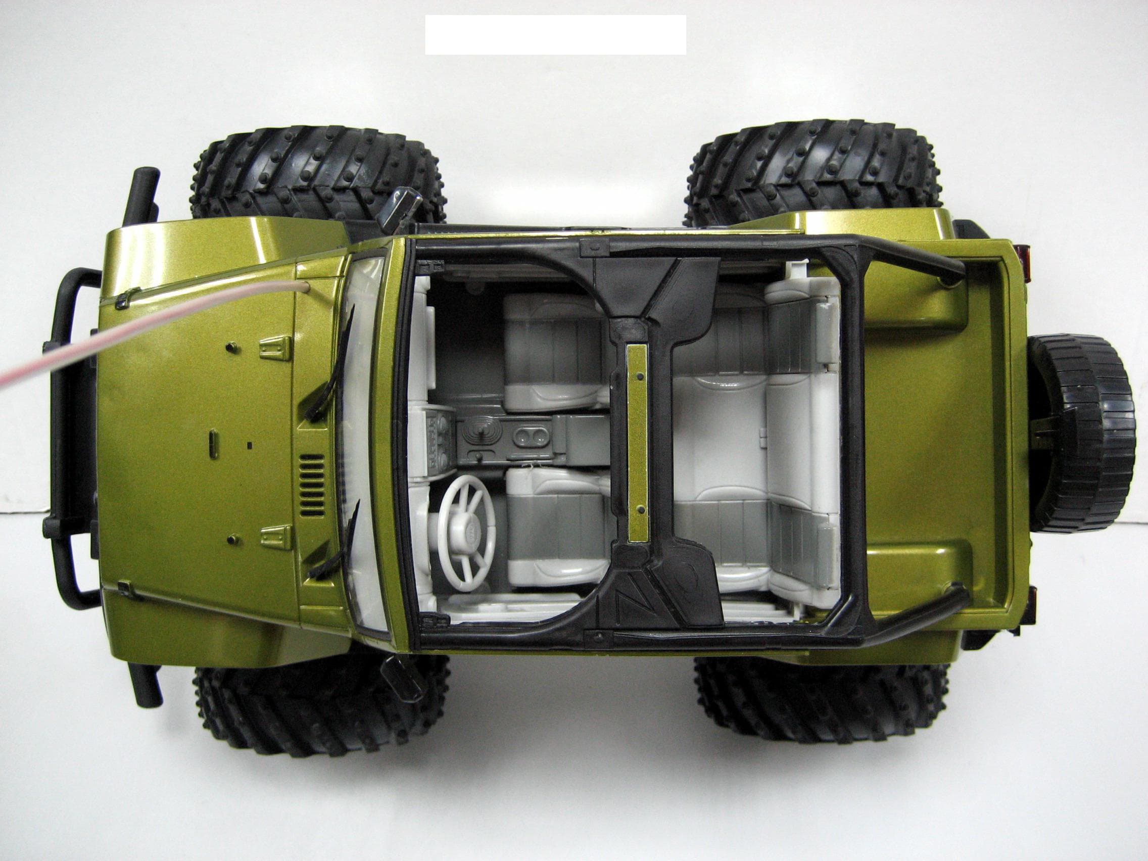
GLE8251
Jul 26, 2007RC Helicopter
Equipment Class
DXX - Part 15 Low Power Communication Device Transmitter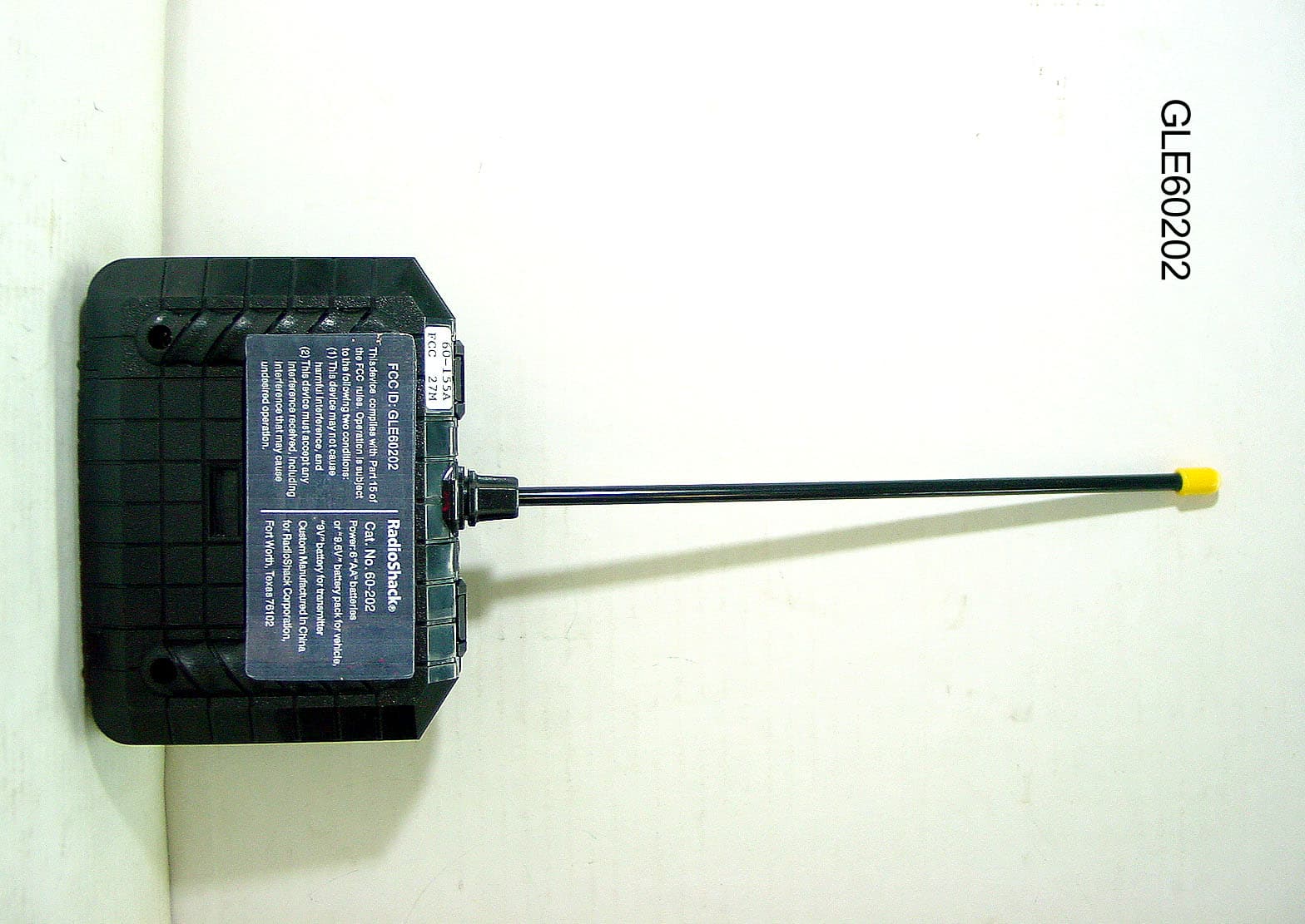
GLE60202
Jun 17, 2007Wireless Remote Control Toy Transmitter
Equipment Class
DXX - Part 15 Low Power Communication Device Transmitter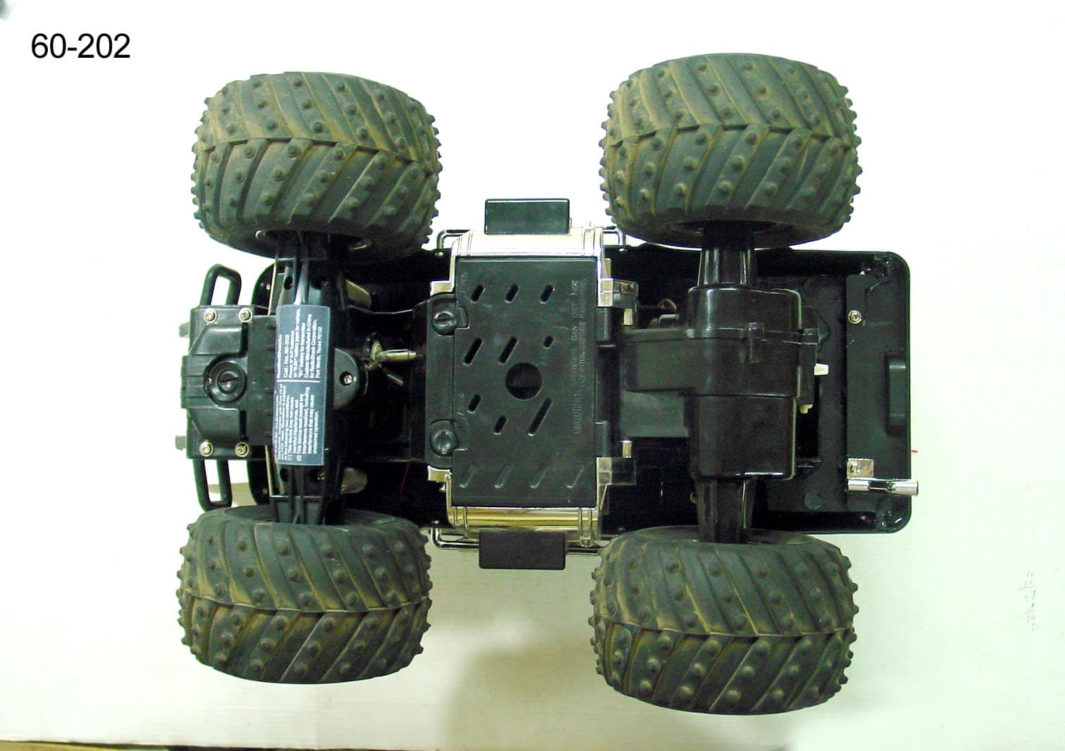
GLE60202R
Jun 17, 2007Wireless Remote Control Toy Receiver
Equipment Class
CYY - Communications Receiver used w/Pt 15 Transmitter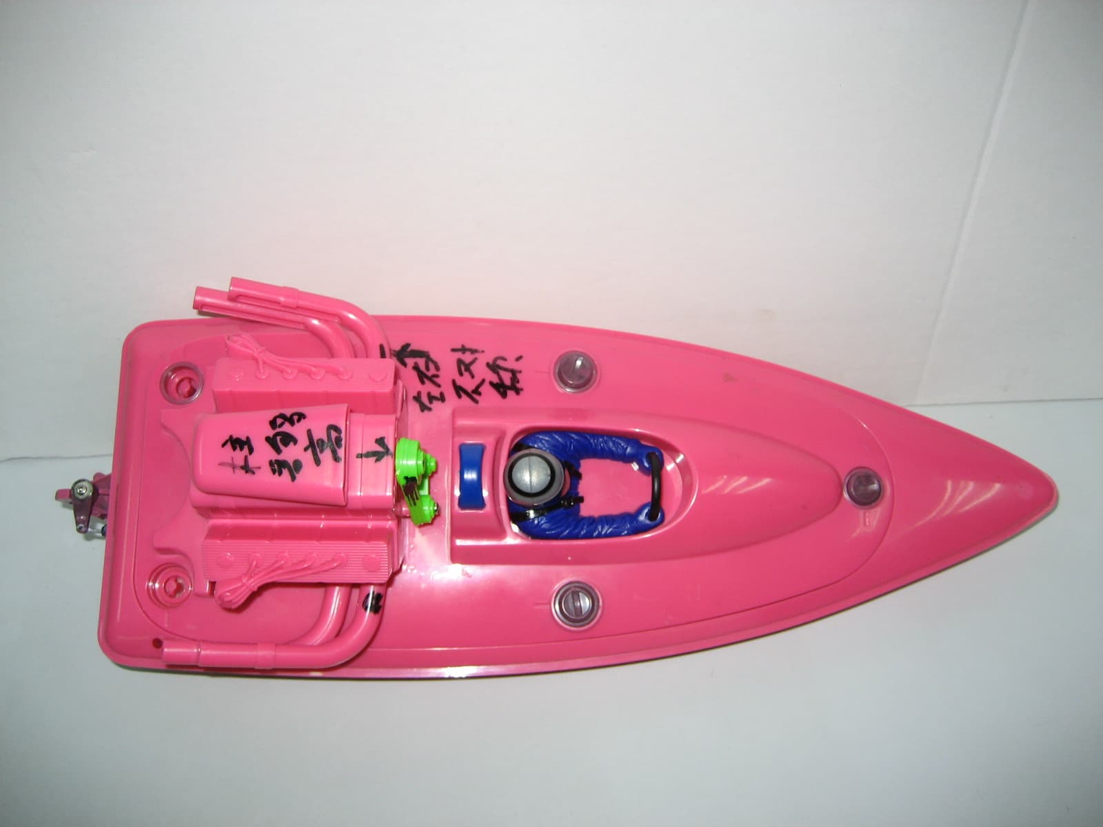
GLE60153R
Jan 15, 2007WIRELESS REMOTE CONTROL RECEIVER
Equipment Class
CRR - Superregenerative Receiver