GLE607090TREMOTE CONTROL TRANSMITTER
Suncon Toys Industry Ltd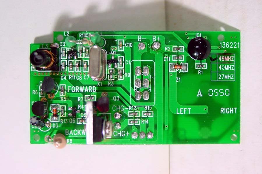
Click to zoom
Application Details
- Equipment Class
- DXX - Part 15 Low Power Communication Device Transmitter
- Date of Grant
- Feb 01, 2006
- Application Purpose
- Original Equipment
- Date of Application
- Feb 01, 2006
- Equipment Note
- REMOTE CONTROL TRANSMITTER
- Frequency Range
- 49.86000000 - 49.86000000
- Company
- Suncon Toys Industry Ltd
- Country
- Hong Kong
Documents & Files
Document Text
Text extracted from the exhibit documents filed with the FCC. Open a document above to read the original.
Users Manual
It’s the ultimate radio-control experience! Your Starter Kit comes with a radio controller and a ZipZaps micro RC with all factory parts. All parts are pre-assembled, race your ZipZaps just out of the package with a quick charge of about 60 seconds. . Light up the race track with your ZipZaps headlights. . Carry your 1:64 scales tunable ZipZaps in your pocket. . ZipZaps provide great fun for ages 8 and up. To really rev up the fun factor, customize your ZipZaps micro RC with optional performance upgrade kits, viewable at the ZipZaps Showroom at www.zipzaps.com and available at your local RadioShack. Follow these simple steps to make your ZipZaps race ready. 1. Starter Kit Includes Your ZipZaps micro RC Starter Kit includes everything you see here. All parts are pre-assembled and ready to race for your quickest fun. Controller (illus) Tires (illus) Hubcaps (illus) Body Top (illus) Chassis (illus) Motor clip with set screw (illus) Performance motor with drive gear (illus) Transfer gear (illus) Screwdriver (illus) Rear axle gear (illus) Wrist strap (illus) 2. Power Up Your Controller The CONTROLLER charges your micro RC and controls its steering and speed. You’ll need to install four AAA 1.5V batteries (not included). The ZipZaps factory recommends RadioShack Enercell Plus alkaline batteries. 1. Set ON/OFF on the CONTROLLER to OFF. 2. Use the SCREWDRIVER stored at the bottom of the CONTROLLER to loosen the screw and remove the battery compartment cover. (illus) 3. Place four AAA 1.5V batteries in the compartment according to the polarity symbols (+ and -) marked inside. (illus) 4. Replace the cover and secure it with the screw. If you notice the range of your CONTROLLER decreasing, it is time to replace the batteries. Battery Notes - Use only fresh batteries of the required size and recommended type. - Do not mix old and new batteries, different types of batteries (standard, alkaline or rechargeable) or rechargeable batteries of different capacities. - If you do not plan to use the micro RC for several days, remove all the batteries from the CONTROLLER. Batteries can leak chemicals that can destroy electronic parts. - Never leave dead or weak batteries in the CONTROLLER. - Dispose of dead batteries promptly and properly. Do not burn or bury them. 3. Zap Your Car On The Charger Your micro RC comes with a built-in Ni-MH rechargeable battery for power. You can charge the battery using the power from the CONTROLLER. Set ON/OFF on the CONTROLLER to ON. The indicator light turns green. Open the cover on the top of the CONTROLLER. Align the metal contact points on the car’s chassis with the metal contact points on top of the CONTROLLER. Place the micro RC as shown and snap it into position – it will lock automatically. The CONTROLLER indicator light turns red to let you know it’s charging. (illus) The CONTROLLER indicator light turns green when the micro RC is fully charged. Press the RELEASE button to unlock the micro RC. Caution: - Always use the RELEASE button when removing your micro RC from the charger. (illus) - If your micro RC runs slowly, or not at all, or does not respond to the CONTROLLER, recharge it. - After you charger charge or recharge your micro RC, disconnect it from the CONTROLLER. Overcharging the micro RC could damage it. 4 Zoom Away! For optimum racing conditions, use a smooth, flat surface. Avoid rugs, carpets, and family pets! Warning: Do not run your micro RC in the street. Open the removable cover on top of the CONTROLLER. Fully extend the antenna. (illus) Set ON/OFF on the CONTROLLER to ON. The ON/OFF indicator lights green. Steering: Use the CONTROLLER buttons to drive and steer. Left Control Button (illustration) . Press forward to move forward . Release to stop . Press backward to move backward Right control Button (illustration) . Press left to turn left . Release to go straight . Press right to turn right When you’re finished driving, slide ON/OFF on the CONTROLLER to OFF and retract the CONTROLLER’s antenna. 5. Performance Adjustments Wheel alignment If your micro RC does not drive in a straight line when you release the right control lever, adjust the wheel alignment control on the bottom of the micro RC. Use the supplied screwdriver to turn the control toward L if your micro RC is pulling to the right or toward R if it is pulling to the left. (illus) 6. Attach the Wrist Strap Attach the WRIST STRAP as shown below to prevent dropping your CONTROLLER. Thread the string through the hole on the left side of the CONTROLLER as shown, and then thread the strap through the ring of the string. (illus) 7. Tune Your Car with upgraded parts Your micro RC is factory pre-assembled. Here show how is the ZipZaps is assembled for your own customization. 1. Mount the HUBCAPS to the front axle wheels, then press the TIRES over the HUBCAPS as shown. (illus) 2. Install the PERFORMANCE MOTOR WITH DRIVE GEAR in the groove on the back of the CHASSIS. Carefully snap the MOTOR CLIP WITH SET SCREW into the groove closest to the MOTOR as shown. (illus) 3. Rotate the MOTOR CLIP WITH SET SCREW as shown below to set the MOTOR in position. 4. Secure the MOTOR CLIP WITH SET SCREW with the SCREWDRIVER, which is stored at the bottom of the CONTROLLER. Plug the TRANSFER GEAR into the axle as shown. (illus) Caution: Do not overtighten the SET SCREW. (illus) 5. Plug the HUBCAPS into the REAR AXLE GEAR, and press the TIRES over the HUBCAPS. Next, secure the REAR AXLE GEAR assembly into the CHASSIS as shown. (illus) 6. Plug the LED connector of the car top into the car chassis’ male connector as shown. 7. Thread the ANTENNA through the hole in the BODY TOPS. Snap the BODY TOP to the back of the CHASSIS, then secure the front by gently pushing the BODY TOP onto the CHASSIS as shown. (illus) 8. Zip Tips • If your micro RC’s motor runs or your car responds erratically or sluggishly • move closer to your micro RC, b) be sure your hand is not touching the CONTROLLER’S antenna, or c) check the batteries. • I…
Text truncated - open the document above for the full version.
Internal Photos
SUNCON TOYS INDUSTRY LTD. FCC ID: GLE607090T INTERNAL PHOTOS
Test Report
TIMCO ENGINEERING INC. 849 NW State Road 45 Newberry, Florida 32669 http://www.timcoengr.com 888.472.2424 F 352.472.2030 email: [email protected] APPLICANT: SUNCON TOYS INDUSTRY LTD. FCC ID: GLE607090T REPORT #: S\SUNCONGLE\146UT6\146UT6TestReport.doc COVER SHEET Test Report Product Name: REMOTE CONTROL TRANSMITTER FCC ID: GLE607090T Applicant: SUNCON TOYS INDUSTRY LTD. 11/F, KAI TAK FACTORY BUILDING 99 KING FUK STREET SANPOKONG, KOWLOON, HONG KONG HONG KONG Date Receipt: 1/23/2006 Date Tested: 1/30/2006 TIMCO ENGINEERING INC. 849 NW State Road 45 Newberry, Florida 32669 http://www.timcoengr.com 888.472.2424 F 352.472.2030 email: [email protected] APPLICANT: SUNCON TOYS INDUSTRY LTD. FCC ID: GLE607090T REPORT #: S\SUNCONGLE\146UT6\146UT6TestReport.doc TABLE OF CONTENTS TABLE OF CONTENTS LIST APPLICANT: SUNCON TOYS INDUSTRY LTD. FCC ID: GLE607090T TEST REPORT CONTAINING: PAGE 1.............TEST EQUIPMENT LIST PAGE 2.............TEST PROCEDURE PAGE 3.............RADIATION INTERFERENCE TEST DATA PAGE 4.............OCCUPIED BANDWIDTH PAGE 5.............OCCUPIED BANDWIDTH PLOT EXHIBITS INCLUDING: BLOCK DIAGRAM SCHEMATIC INSTRUCTION MANUAL LABEL SAMPLE LABEL LOCATION EXTERNAL PHOTOGRAPHS INTERNAL PHOTOGRAPHS CIRCUIT DESCRIPTION TEST SET UP PHOTOGRAPH TIMCO ENGINEERING INC. 849 NW State Road 45 Newberry, Florida 32669 http://www.timcoengr.com 888.472.2424 F 352.472.2030 email: [email protected] APPLICANT: SUNCON TOYS INDUSTRY LTD. FCC ID: GLE607090T REPORT #: S\SUNCONGLE\146UT6\146UT6TestReport.doc Page 1 of 5 Equipment List Device Manufacturer Model Serial Number Cal/Char Date Due Date 3/10-Meter OATS TEI N/A N/A Listed 3/27/04 3/26/07 3-Meter OATS TEI N/A N/A Listed 1/11/06 1/10/09 Biconnical Antenna Eaton 94455-1 1057 CAL 12/12/05 12/12/07 Biconnical Antenna Eaton 94455-1 1096 CAL 8/17/04 8/17/06 Biconnical Antenna Electro-Metrics BIA-25 1171 CAL 4/29/05 4/29/07 Blue Tower Quasi-Peak Adapter HP 85650A 2811A01279 CAL 4/13/05 4/13/07 Blue Tower RF Preselector HP 85685A 2926A00983 CAL 9/5/05 9/5/07 Blue Tower Spectrum Analyzer HP 8568B 2928A04729 2848A18049 CAL 4/13/05 4/13/07 LISN Electro-Metrics ANS-25/2 2604 CAL 8/27/04 8/27/06 LISN Electro-Metrics EM-7820 2682 CAL 4/28/05 4/28/07 Log-Periodic Antenna Eaton 96005 1243 CAL 12/14/05 12/14/07 TIMCO ENGINEERING INC. 849 NW State Road 45 Newberry, Florida 32669 http://www.timcoengr.com 888.472.2424 F 352.472.2030 email: [email protected] APPLICANT: SUNCON TOYS INDUSTRY LTD. FCC ID: GLE607090T REPORT #: S\SUNCONGLE\146UT6\146UT6TestReport.doc Page 2 of 5 TEST PROCEDURE GENERAL: This report shall NOT be reproduced except in full without the written approval of TIMCO ENGINEERING, INC. RADIATION INTERFERENCE: The test procedure used was ANSI STANDARD C63.4-2003 using a HEWLETT PACKARD spectrum analyzer with a pre-selector. The bandwidth of the spectrum analyzer was 100 kHz with an appropriate sweep speed. The analyzer was calibrated in dB above a microvolt at the output of the antenna. The resolution bandwidth was 100 kHz and the video bandwidth was 300 kHz. The ambient temperature of the UUT was 80ºC with a humidity of 76%. FORMULA OF CONVERSION FACTORS: The Field Strength at 3m was established by adding the meter reading of the spectrum analyzer (which is set to read in units of dBuV) to the antenna correction factor supplied by the antenna manufacturer. The antenna correction factors are stated in terms of dB. The gain of the Pre- selector was accounted for in the Spectrum Analyzer Meter Reading. Example: Freq (MHz) METER READING + ACF = FS 33 20 dBuV + 10.36 dB = 30.36 dBuV/m @ 3m ANSI STANDARD C63.4-2003 10.1.7 MEASUREMENT PROCEDURES: The unit under test was placed on a table 80 cm high and with dimensions of 1m by 1.5m. The table used for radiated measurements is capable of continuous rotation. When an emission was found, the table was rotated to produce the maximum signal strength. At this point, the antenna was raised and lowered from 1m to 4m. The antenna was placed in both the horizontal and vertical planes. TIMCO ENGINEERING INC. 849 NW State Road 45 Newberry, Florida 32669 http://www.timcoengr.com 888.472.2424 F 352.472.2030 email: [email protected] APPLICANT: SUNCON TOYS INDUSTRY LTD. FCC ID: GLE607090T REPORT #: S\SUNCONGLE\146UT6\146UT6TestReport.doc Page 3 of 5 APPLICANT: SUNCON TOYS INDUSTRY LTD. FCC ID: GLE607090T NAME OF TEST: RADIATION INTERFERENCE RULES PART NO.: 15.235 REQUIREMENTS: CARRIER FREQUENCY WILL NOT EXCEEDS 80 dBuV/m AT 3M. OUT-OF-BAND EMISSIONS SHALL NOT EXCEED: 30 - 88 MHz 40.0 dBuV/M MEASURED AT 3 METERS 88 - 216 MHz 43.5 dBuV/M 216 - 960 MHz 46.0 dBuV/M ABOVE 960 MHz 54.0 dBuV/M TEST DATA: Tuned Frequency MHz Emission Frequency MHz Meter Reading dBuV Ant. Polarity Coax Loss dB Correction Factor dB Field Strength dBuV/m Margin dB 49.9 49.86 55.2 H 0.50 11.20 66.90 13.10 49.9 49.86 63.0 V 0.50 11.07 74.57 5.43 No harmonics or other emissions found. SAMPLE CALCULATION: FSdBuV/m = MR (dBuV) + ACFdB. TEST PROCEDURE: The procedure used was ANSI STANDARD C63.4-2003. The spectrum was scanned from 30 MHz to 1000 MHz. When an emission was found, the table was rotated to produce the maximum signal strength. The antenna was placed in both the horizontal and vertical planes and the worse case emissions were reported. Emissions attenuated more than 20 dB below the permissible value are not reported. The UUT was tested in 3 orthogonal planes. PERFORMED BY: RICHARD BLOCK DATE: 1/30/2006 TIMCO ENGINEERING INC. 849 NW State Road 45 Newberry, Florida 32669 http://www.timcoengr.com 888.472.2424 F 352.472.2030 email: [email protected] APPLICANT: SUNCON TOYS INDUSTRY LTD. FCC ID: GLE607090T REPORT #: S\SUNCONGLE\146UT6\146UT6TestReport.doc Page 4 of 5 APPLICANT: SUNCON TOYS INDUSTRY LTD. FCC ID: GLE607090T NAME OF TEST: Occupied Bandwidth RULES PART NO.: 15.235 REQUIREMENTS: The field strength of any emissions appearing between the band edges and up to 10 kHz above and below the band edges shall be attenuated at least 26 dB below the le…
Text truncated - open the document above for the full version.
Contact Information
Applicant
Garry Feung
852 2352-3268Fax: 852 2352-3267
Test Firm
Timco Engineering, Inc.Sid Sanders
Technical Specifications
| # | Rule Parts | Frequency Range | Power Output |
|---|---|---|---|
| 1 | 15C | 49.86 MHz - 49.86 MHz | - |
Other Applications from Suncon Toys Industry Ltd
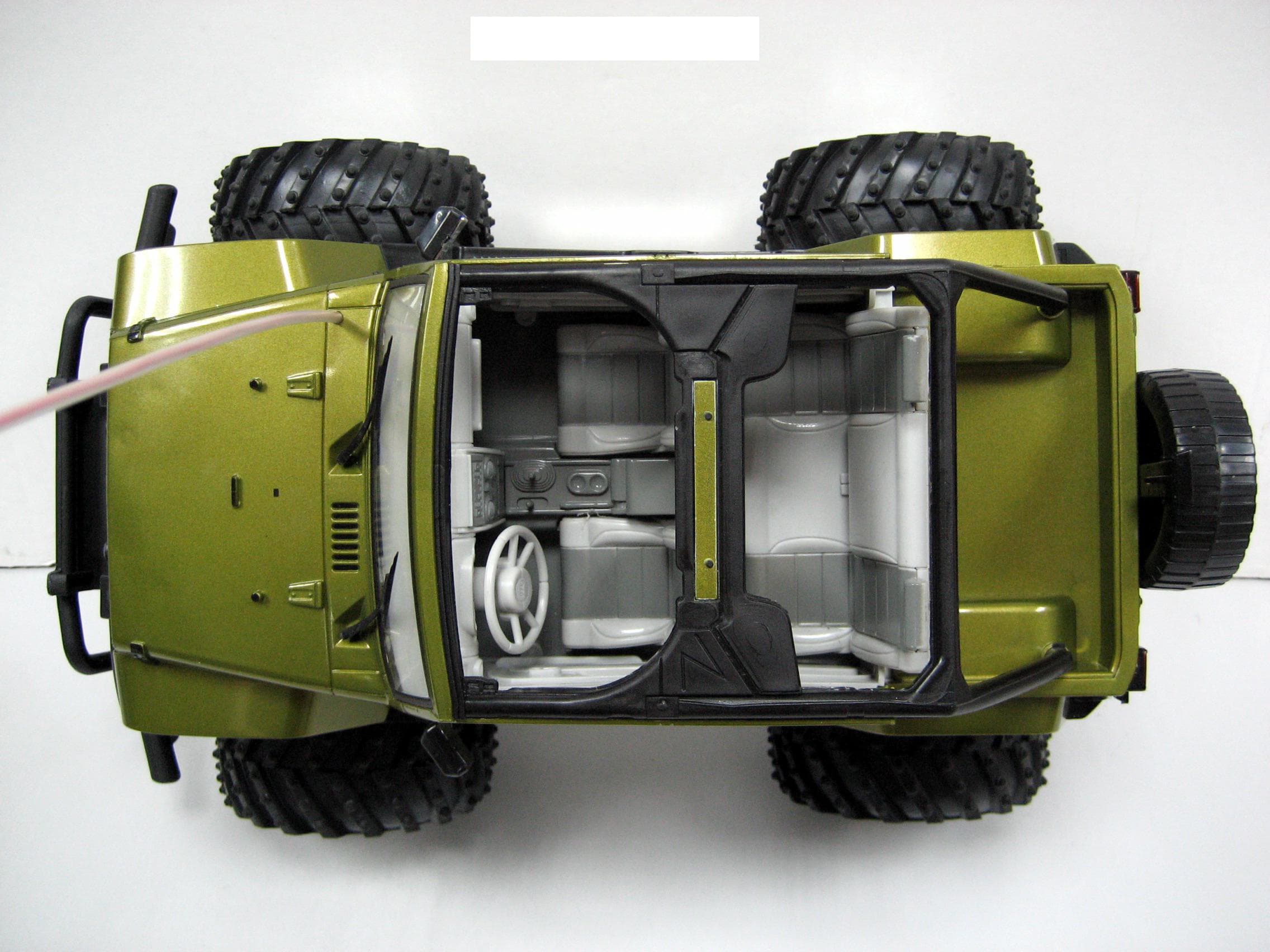
GLE136227R
Mar 26, 200849.82-49.90 MHZ WIRELESS R/C TOY-RX
Equipment Class
CYY - Communications Receiver used w/Pt 15 Transmitter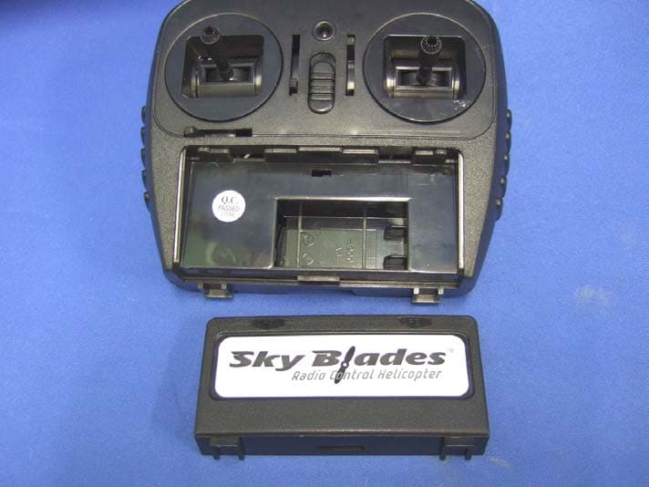
GLE8251
Jul 26, 2007RC Helicopter
Equipment Class
DXX - Part 15 Low Power Communication Device Transmitter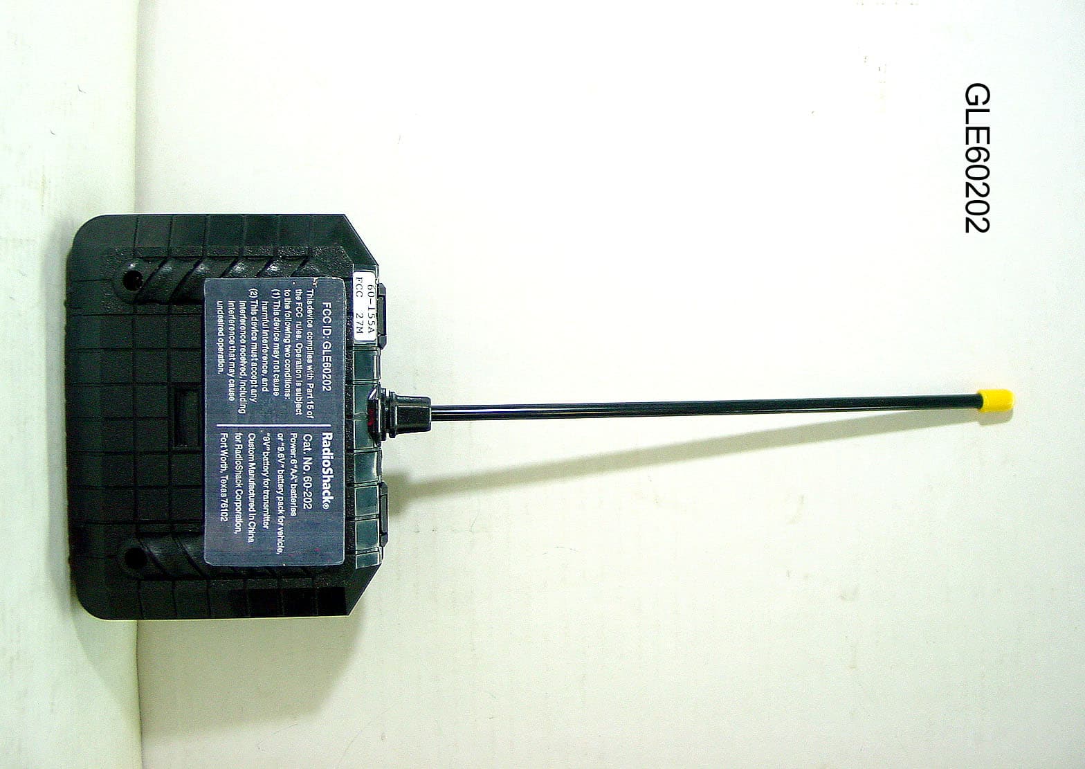
GLE60202
Jun 17, 2007Wireless Remote Control Toy Transmitter
Equipment Class
DXX - Part 15 Low Power Communication Device Transmitter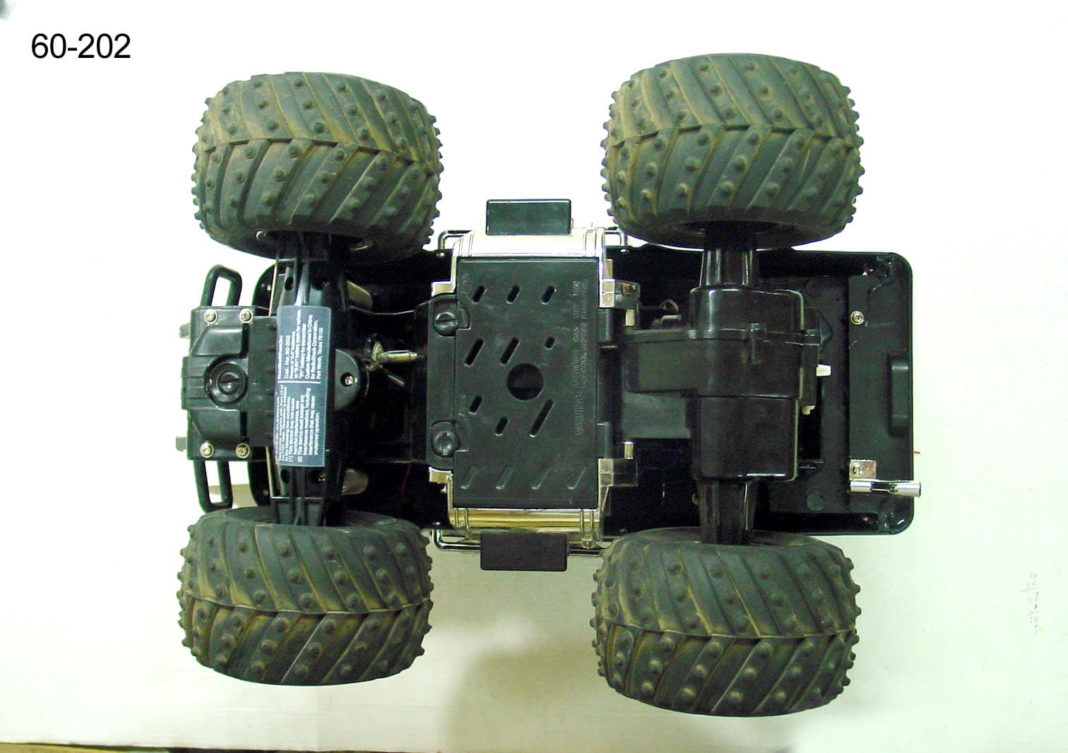
GLE60202R
Jun 17, 2007Wireless Remote Control Toy Receiver
Equipment Class
CYY - Communications Receiver used w/Pt 15 Transmitter
GLE60153R
Jan 15, 2007WIRELESS REMOTE CONTROL RECEIVER
Equipment Class
CRR - Superregenerative Receiver