GNW21100Ricochet GS wireless Modem
Ricochet Networks, Inc.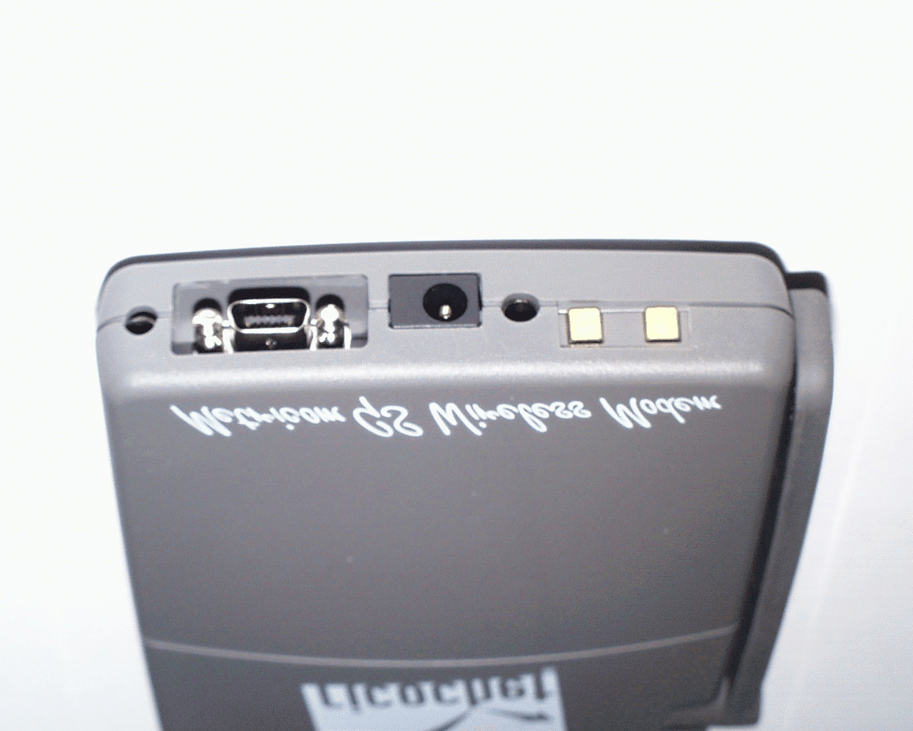
Click to zoom
Application Details
- Equipment Class
- DSS - Part 15 Spread Spectrum Transmitter
- Date of Grant
- Mar 05, 2000
- Application Purpose
- Original Equipment
- Date of Application
- Aug 04, 1999
- Equipment Note
- Ricochet GS wireless Modem
- Frequency Range
- 902.00000000 - 928.00000000
- Company
- Ricochet Networks, Inc.
- Country
- United States
Documents & Files
Document Text
Text extracted from the exhibit documents filed with the FCC. Open a document above to read the original.
Operational Description
Metricom, Inc. 980 University Avenue Los Gatos, CA, 93030 (Tel)408-399-8200 (Fax) 408-354-1024 3 March 2000 Federal Communications Commission Equipment Authorization Division Applications Processing Branch 7435 Oakland Mills Road Columbia, MD. 21046 Dear Sir or Madam, In reference to the application for Certification under FCC ID GNW21100, Metricom requests that the following materials submitted with the Permissive Change Request be withheld from public disclosure. 1. Electrical Schematics, RF and Digital 2. Block Diagrams, RF and Digital 3. Any “Theory of Operations” that may have been provided with the application Thank you, David Waitt Prod Evaluation & Reliability Eng.
RF Exposure Info
MPE Assessment for the GS Wireless Modem, GNW 21100 Exposure.docGS Wireless Modem MPE Calculations07/29/99 Metricom, Inc. 980 University Avenue Los Gatos, CA, 93030 (Tel)408-399-8200 (Fax) 408-354-1024 Federal Communications Commission Maximum Permissible Exposure Assessment for the Metricom GS modem, GNW 21100 In accordance with FCC REPORT AND ORDER 96-326 Adopted: August 1, 1996 MPE Assessment for the GS Wireless Modem, GNW 21100 Exposure.docGS Wireless Modem MPE Calculations07/29/99 Background: The Metricom GS wireless modem is a frequency hopping spread spectrum radio-modem that operates within the 902-928 MHz band. The peak transmit output power of the radio is 1 Watt. The modem is capable of communicating with either Micro-Cellular Data Network (MCDN) microcell radios (GNW 21000) that make up the MCDN network or other MCDN compatible wireless modems. The modem uses a 1 dBi gain omni-directional monopole antenna. Testing has determined that the typical Tx duty cycle for a modem communicating over the MCDN network is less than 5%. Even though the 5% level is at the upper limit of typical operation, a duty cycle of 100% is used here to yield a worst case analysis. The modem is a classified as a mobile device and is intended to be mounted to the back of a laptop computer display or sit on the desk next to the laptop computer. MPE Calculations. The environment in which the modem operates is “uncontrolled”. The definitions of controlled and uncontrolled environments are included below from the FCC Report and Order 96-326: B. Definitions of Controlled and Uncontrolled Environments 35. The 1992 ANSI/IEEE guidelines specify two sets of exposure limits based on the "environment" in which the exposure takes place. These environments are classified as either "controlled" or "uncontrolled." Controlled environments are defined as locations where "there is exposure that may be incurred by persons who are aware of the potential for exposure as a concomitant of employment, by other cognizant persons, or as the incidental result of transient passage through areas where analysis shows the exposure levels may be above [the exposure and induced current levels permitted for uncontrolled environment but not those permitted for controlled environments]." Uncontrolled environments are defined as "locations where there is the exposure of individuals who have no knowledge or control of their exposure. The exposures may occur in living quarters or workplaces where there are no expectations that the exposure levels may exceed [the exposure and induced current levels permitted for uncontrolled environments]." Uncontrolled Environment Spec:f(MHz)/1500 mW/cm^2 902/1500 = .6 mW/cm^2 In this case the modem may be mounted behind the monitor of a laptop or sitting on the desk next to the laptop that it is connected to. If the modem is on the desk next to the laptop, then the minimum distance between the user would typically be 5 inches. If the unit were mounted on the back of a laptop display, the typical minimum distance would be approximately 12 to 15 inches. Calculation: MPE Dist(cm)= SQRT( (Ant Gain(Ratio)*Pout(mw)*Duty Cycle)/(Limit(mw/cm^2) *4 * PI) ) = SQRT( ( 1.25 * 1000 * 1 / .6 *4 * PI) ) = SQRT( (1250/ 7.5398) ) = SQRT (165.786) MPE Dist(cm) = 12.87 cm MPE Dist(in) = 5.06 in Conclusion: The typical distance between the user of the modem is approximately 2 to 3 times greater than the MPE distance under typical use. A statement will appear in the front of the modem user manual that will inform users of the MPE distance and recommend that during extended periods of operation the user maintain the MPE distance between themselves and the modem. MPE Distance (cm) Antenna Gain (as a ratio) * Pout(mw) * Duty Cycle Exposure Limit ( mw/cm^2) * 4 * Π MPE Assessment for the GS Wireless Modem, GNW 21100 Exposure.docGS Wireless Modem MPE Calculations07/29/99 Exposure Limits from FCC96-326 Report and Order, Appendix C, Final Rules is given below. Table 1. Limits for Maximum Permissible Exposure (MPE) (B) Limits for General Population/Uncontrolled Exposure ______________________________________________________________________________ Frequency Electric FieldMagnetic Field Range Strength Strength Power Density Averaging Time (MHz) (V/m) (A/m) (mW/cm2) (minutes) ______________________________________________________________________________ 0.3-1.34 614 1.63 (100)* 30 1.34-30 824/f 2.19/f (180/f2)* 30 30-300 27.5 0.073 0.2 30 300-1500 -- -- f/1500 30 1500-100,000 -- -- 1.0 30 ______________________________________________________________________________ f = frequency in MHz * = Plane-wave equivalent power density NOTE 1 TO TABLE 1: Occupational/controlled limits apply in situations in which persons are exposed as a consequence of their employment provided those persons are fully aware of the potential for exposure and can exercise control over their exposure. Limits for occupational/controlled exposure also apply in situations when an individual is transient through a location where occupational/controlled limits apply provided he or she is made aware of the potential for exposure. NOTE 2 TO TABLE 1: General population/uncontrolled exposures apply in situations in which the general public may be exposed, or in which persons that are exposed as a consequence of their employment may not be fully aware of the potential for exposure or can not exercise control over their exposure.
RF Exposure Info
David Waitt Metricom, Inc. 980 University Avenue Los Gatos, CA, 93030 (Tel) 408-399-8126 (eFax) 603-737-7845 [email protected] 29 Nov 1999 To:Federal Communications Commission Equipment Authorization Division Applications Processing Branch Errol Chang [email protected] Re:731 Conf. number:EA95065 FCC ID:GNW21100 Correspondence Ref Number:10187 Below are Metricom’s replies to the FCC’s comments regarding the above application. FCC COMMENT 1. The filing is requesting for 1.0 W. Maximum measured output is 837 mW at the antenna terminal. Requested output needs revision. Metricom Reply A new 731 form will be submitted with the RF output power specified at 837 mW. FCC COMMENT 2. The user manual is indicating "device does not comply with Part 15 Rules". The RF exposure statement at the end of this section needs revision, it has the wrong separation distance (see below). Metricom Reply The manual that was submitted in the application was the manual that was printed up for the Beta test users. At that time, since certification had not been granted, the statement said that the device did not comply with the FCC specifications. The statement that will appear in the final version of the user manual is below. FCC Compliance This device complies with part 15 of the FCC Rules. Operation is subject to the following two conditions: (1) This device may not cause harmful interference, and (2) this device must accept any interference received, including interference that may cause unwanted operation This equipment has been tested and found to comply with the limits for a Class B digital device, pursuant to Part 15 of the FCC rules. These limits are designed to provide reasonable protection against harmful interference in a residential installation. This equipment generates, uses and can radiate radio frequency energy and, if not installed and used in accordance with the instructions, may cause harmful interference to radio communications. However, there is no guarantee that interference will not occur in a particular installation. If this equipment does cause harmful interference to radio or television reception, which can be determined by turning the equipment off and on, the user is encouraged to try to correct the interference by one or more of the following safety measures. • Reorient or relocate the receiving antenna. • Increase the separation between the equipment and the receiver. • Consult the dealer or an experienced radio/modem technician for help. To comply with FCC RF exposure limits, during normal operation, the user should maintain a minimum separation distance of 8 inches between all persons and the antenna of this device. FCC COMMENT 3. The distance determined by the MPE estimates is 12.87 cm, rounding up to 13 cm, which is inconsistent with the distance indicated in the operators manual. Metricom has declared this to be a "mobile" transmitter for mounting behind lap-top computer displays or on desk-top next to lap-top computers, and estimated RF exposure compliance with respect to MPE limits. A minimum separation distance of 20 cm is required with respect to 2.1091 of FCC Rules. The manual instructions/statements should be revised accordingly; otherwise, compliance must be estimated with respect to 2.1093 using SAR limits (when less than 20 cm). Metricom Reply Since classifying the modem as a “mobile” device results in a required minimum separation distance of 20 cm. (approx. 8 inches) even though the MPE distance is less that 20 cm, Metricom will modify the users manual to reflect this 20 cm minimum distance. (See the statement above) Additionally Metricom has recalculated the MPE distance using the corrected RF power output of 837 mw and the new MPE estimate is in this document as well. FCC COMMENT 4. The RF exposure statement/instruction indicated in the manual should indicated that when this device is operating, a separation distance of 20 cm or more must be maintained between its antenna and all persons, including users and bystanders, to satisfy FCC RF Exposure requirements. Time-averaging according to typical usage, such as "continuous or extended data transmission" (currently indicated) for purpose of RF exposure is only allowed for controlled exposure environment, which does not apply to this device. The separation distance is a requirement for device operating as a mobile transmitter, not a recommendation as currently indicated in the manual. The statement should be revised accordingly. Metricom Reply The statement in the manual has been revised as suggested above. FCC COMMENT 5. As proposed in the MPE estimates, the device is for lap-top computer use either attached to the back of the display or on desk-top next to the lap-top computer. Operating instructions and procedures, including the required separation distance, should be included in the users manual for these proposed operating conditions for satisfying 15.247(b)(4). Metricom Reply The statement in the front of the manual has been revised (See statement above). Additionally, a note informing the user of the minimum separation distance has been placed in the manual within the instructions where the user is instructed to turn the modem on. The note that will appear in the final version of the manual is below. Note: To comply with FCC RF exposure limits, during normal operation, the user should maintain a minimum separation distance of 8 inches between all persons and the antenna of this device. Metricom, Inc. 980 University Avenue Los Gatos, CA, 93030 (Tel)408-399-8200 (Fax) 408-354-1024 Federal Communications Commission Maximum Permissible Exposure Assessment for the Metricom GS modem, GNW 21100 In accordance with FCC REPORT AND ORDER 96-326 Adopted: August 1, 1996 Background: The Metricom GS wireless modem is a frequency hopping spread spectrum radio-modem that operates within the 902-928 MHz band. The peak transmit output power of the radio is 1 Watt. The modem is capable of communicating with either Micro-Cellular Data Net…
Text truncated - open the document above for the full version.
Test Report
Metricom, Inc. 980 University Avenue Los Gatos, CA, 93030 (Tel)408-399-8200 (Fax) 408-354-1024 Part 15 Certification Application for FCC ID 21100 EMI Test Report and Technical Documentation on Alps, Inc. Wireless Modem for use on the Metricom MCDN Network Prepared by: Metricom, Inc 980 University Ave. Los Gatos, CA 95032 Test date(s): June 1999 Schematics, block diagrams and algorithm descriptions subject to enclosed confidentiality statement Metricom, Inc.FCC Part 15 Certification ApplicationJuly 1999 Woody_app.doc (dw8)Page #:2 1.0 Verification of Compliance Description:Ricochet GS Wireless Modem Model Number:21100 Serial Number(s):Pre-Production Models Applicant:Metricom Inc. Type of Test:FCC part 15.247 Application for Part 15 Certification under GNW 21100 Date(s) of test:June 1999 Tested ByDavid Waitt (Metricom, Los Gatos) Electronic Compliance Laboratories. (EC Labs) The above equipment was tested by Metricom Inc. and EC Labs and found to be in compliance with the requirements set forth in Part 15 of the FCC Rules and Regulations. David Waitt Engineer Metricom, Inc. Metricom, Inc.FCC Part 15 Certification ApplicationJuly 1999 Woody_app.doc (dw8)Page #:3 2.0General Information Applicant:Metricom, Inc 980 University Ave Los Gatos, CA 95032 Contact PersonDavid Waitt Equipment Under Test:Ricochet GS Wireless Modem Model Number:21100 Serial Number(s):Pre-Production models Manufacturer:Alps, Inc. Type of Test:FCC Part 15.247 Certification, FCC ID GNW-21020 Reason for testing:Alps has developed, for Metricom, Inc. a new version of the Ricochet Wireless modem. It is similar in general functionality to the current Ricochet Wireless modem (FCC GNW 21062 ). The Ricochet Wireless modem operates on Metricom’s MCDN wireless network. The modem will be sold or rented to subscribers of Metricom’s Ricochet service. The Ricochet service allows subscribers to send / receive email, connect to the Internet, ect. without the necessity of a telephone line. The Ricochet GS modem (Model 21100) is a frequency hopping spread spectrum radio- modem that operates within the 902-928 MHz band. The modem transmits and receives digital packet data. The transmit power of the modem is 1 Watt. The modems are capable of communicating with MCDN radios that make up the MCDN network or other modems. A technical overview of the MCDN network is contained in the Appendix. The new GS Ricochet modem is similar to the current Ricochet modem. The most notable differences are: Modulation: The new modem employs a number of possible modulations. However, in normal operation, pi/4 DPSK modulation will be used currently. This allows for faster data transfer between the modem and the MCDN network radios Metricom, Inc.FCC Part 15 Certification ApplicationJuly 1999 Woody_app.doc (dw8)Page #:4 3.0Results Summary Summary:Since this is a new certification request, a complete set of tests demonstrating compliance with FCC Part 15.247 was conducted. Compliance with the following Part 15 regulations was verified: Paragraph Test Results 15.247(b)Maximum Power Output at Antenna Terminals+ 29.23dBm Max 15.247(a)(1)(i)Minimum Number of Hopping Channels 50 Demonstrated 50 (Actual) 15.247(a)(1)Channel Frequency Separation 160 kHz (by design) 15.247(a)(1)Average Channel Occupancy Time194 ms / 20 Sec Avg. 15.247(c)Out of Band Conducted Emissions- 20.2 dB @ band edge Out of Band Conducted Emissions (1 – 10 GHz)-72dBm @ 1.8 GHz 15.247(c)Out of Band Radiated Emissions9.6 dB in spec, min 15.205Radiated Emissions in Restricted bands 1.7 dB in spec, min 15.109Class B Unintentional Radiated Emissions 9.6 dB in spec, min 4.0 Test Facilities The following tests: 15.247(c)Out of Band Radiated Emissions 15.205Radiated Emissions in Restricted bands 15.207AC Line Conducted Emissions were conducted at: Electronic Compliance Laboratories ( ** ) 1249 Birchwood Drive Sunnyvale, CA. 94089 The remaining tests described in this report were performed at: Metricom, Inc. 980 University Ave Los Gatos, CA. 95030 ( ** ) A description of the sites located at EC Labs is on file at: Federal Communications Commission PO 429 Columbia, MD. 21045 All of the sites at EC Labs are constructed and calibrated to meet ANSI C63.4-1994 requirements. Metricom, Inc.FCC Part 15 Certification ApplicationJuly 1999 Woody_app.doc (dw8)Page #:5 5.0Test Equipment & General Test Methods Equipment: The following test equipment was used to perform the testing Item Desc. Manufacturer Model S/N 1. EMI ReceiverHP8546A3325A00137 2. Pre AmpHP8449B3008A00527 3. LISNEMANS-25/22532 4. PlotterHP7470A2644V00365 5. 20 dB PadHPNANot Req’d 6. Spectrum AnalyzerHP8563A137A01183 7. 2.0 - 4.0 GHz HPFLaboratory GradeNA 8. 4.0 - 10 GHz HPFLaboratory GradeNA 9. Diagnostic SoftwareMetricomDALEC--------- 10. Spectrum AnalyzerHP8563E3450A2982 HP = Hewlett PackardEM = ElectroMetrics ** = Response Plots on file at EC Labs Methods: Many of the tests are performed at the low, middle and the high portion of the 902 - 928 MHz band. These tests are typically performed on the following channels / frequencies: Channel Frequency ( MHz ) 0902.08 75914.08 161927.84 These are referred to as the “Standard Test Channels”. For a complete table of Channel Vs. Frequency, see Appendix B. Many of the tests required that the UUT be operated in modes that are not possible with the normal operating software. In these cases, the UUT was operating on special Diagnostic Software. There are also cases where the UUT has to operate normally, however some special instructions must be sent to the UUT. This is referred to operating the UUT in Diagnostic Mode. The tests below are performed using the basic test setup shown in Fig 1. The only difference between several of the tests is the mode that the UUT is being operated in or the software that the UUT is operating from. Paragraph Test 15.247(a)(1)(i)Minimum Number of Hopping Channels 15.247(a)(1)Channel Frequency Separation 15.247(c)Out of Band Conducted Emissions .4 dB Cable Loss Unit Under Test ( UUT ) A…
Text truncated - open the document above for the full version.
Test Report
Metricom, Inc.FCC Part 15 Certification ApplicationJuly 1999 Woody_app.doc (dw8)Page #:14 FCC RADIATED DATA SHEET DATE: MAR. 3, 1999 EUT:WOODY MODEMCUSTOMER NAME:METRICOM S/N: 44 WORK ORDER: 9030301 RULE PART: 15.247FILE:9030301A.XLS ANTENNA:HORN OTHER CAL FACTORS:ATTN dB: 0 MODULATION TYPE: DUTY dB: 0 TESTED BY: SHAWN HP IL dB:0 COMMENTS: DIST dB: 0 FREQ.READING Pk, QP, A.F.Cable lossAMPO.C.F.TOTAL,LIMITDELTA MHzdB(uV)or AvdBdBdBdBdB(uV/m)dB(uV/m)dB Fund = 902.1 2706.1846.5Pk30.68.135.00.050.274.0-23.8 2706.1836.4Avg30.68.135.00.040.154.0-13.9 3608.2445.5Pk32.59.835.00.052.874.0-21.2 3608.2437.8Avg32.59.835.00.045.154.0-8.9 4510.344.3Pk34.211.735.00.055.274.0-18.8 4510.337.5Avg34.211.735.00.048.454.0-5.6 5412.3643.3Pk34.814.135.00.057.274.0-16.8 5412.3633.6Avg34.814.135.00.047.554.0-6.5 8118.5439.5Pk38.418.335.00.061.274.0-12.8 8118.5429.0Avg38.418.335.00.050.754.0-3.3 9020.638.3Pk40.418.935.00.062.674.0-11.4 9020.628.0Avg40.418.935.00.052.354.0-1.7 Fund = 914.1 R100K/V10Hz 2742.2445.0Pk30.68.135.00.048.774.0-25.3 2742.2438.0Avg30.68.135.00.041.754.0-12.3 3656.3243.0Pk32.510.135.00.050.674.0-23.4 3656.3234.0Avg32.510.135.00.041.654.0-12.4 4570.444.0Pk34.211.935.00.055.174.0-18.9 4570.433.7Avg34.211.935.00.044.854.0-9.2 7312.6438.2Pk36.817.335.00.057.374.0-16.7 7312.6428.0Avg36.817.335.00.047.154.0-6.9 8226.7238.8Pk38.418.235.00.060.474.0-13.6 8226.7228.3Avg38.418.235.00.049.954.0-4.1 9140.839.2Pk40.419.235.00.063.874.0-10.2 9140.827.8Avg40.419.235.00.052.454.0-1.6 Fund = 927.8 2783.5250.8Pk30.68.335.00.054.774.0-19.3 2783.5243.0Avg30.68.335.00.046.954.0-7.1 3711.3647.0Pk32.510.235.00.054.774.0-19.3 3711.3639.2Avg32.510.235.00.046.954.0-7.1 4639.245.3Pk34.211.835.00.056.374.0-17.7 4639.233.8Avg34.211.835.00.044.854.0-9.2 7422.7239.8Pk36.817.235.00.058.874.0-15.2 7422.7229.5Avg36.817.235.00.048.554.0-5.5 8350.5638.8Pk38.418.235.00.060.474.0-13.6 8350.5629.8Avg38.418.235.00.051.454.0-2.6 Metricom, Inc.FCC Part 15 Certification ApplicationJuly 1999 Woody_app.doc (dw8)Page #:15 Electronic Compliance Laboratories, Inc. 1249 Birchwood Ave. Sunnyvale, CA Radiated Emissions Frequency range: 30MHz-1000MHz 3 Meter Open Site Site Calibrated: June 1997 Government Agency and Limit: FCC Class B ------------------------------------------ QP = Quasi-Peak Note: Ignore peak readings when Quasi-Peak reading exists PK = Peak Customer: METRICOM Operator: SHAWN Date: 03-03-1999 Time: 15:11:06 Temperature Range: 64 Deg F Percent Humidity: 44 E.U.T.: WOODY MODEM Serial Number: 44 Support Devices: LAPTOP Serial Number: FCC ID: Exercise Program: Modifications: None Report File Name: F:\TESTDATA\9030301.RF Antenna Type: BICONICAL TEST TEST ACTUAL CLASS B VERSUS TABLE ANTENNA POLAR- DETECTOR FREQ dBuV dBuV/m LIMIT B LIMIT DEGREES HEIGHT IZATION Type ====== ======= ======= ======= ======= ======= ======= ======= ====== 32.000 37.5 30.4 40.0 -9.6 90 1.5 V PK 40.000 32.3 22.0 40.0 -18.0 90 1.5 V PK 112.000 41.0 29.1 43.5 -14.4 150 2.0 V PK 208.000 35.5 27.6 43.5 -15.9 120 2.0 V PK 240.000 36.6 29.1 46.0 -16.9 180 1.5 V PK 256.000 31.1 23.8 46.0 -22.2 180 1.5 V PK 256.000 32.5 25.2 46.0 -20.8 90 1.5 H PK 240.000 40.0 32.5 46.0 -13.5 90 2.0 H PK 216.000 38.0 30.2 43.5 -13.3 120 1.5 H PK 208.000 32.0 24.1 43.5 -19.4 120 2.0 H PK 144.000 42.3 32.7 43.5 -10.8 90 2.0 H PK CHANGED ANTENNA TO LOG PERIODIC ------------------------------- NOTE: NO EMISSIONS DETECTED ABOVE 300Mhz +---------------------------------------------------------------------------+
Contact Information
Applicant
Kathy Eberhart(Paralegal)
Technical Contact
Metricom,Incdavid n waitt
[email protected]408 399 8126
980 university Ave · Los Gatos, California · United States
Non-Technical Contact
Metricom, Inc.Dale n Marquart
[email protected]408 399 8643
Test Firm
Electronic Compliance LaboratoriesChip Matheny
[email protected]408-747-1490
Technical Specifications
| # | Rule Parts | Frequency Range | Power Output |
|---|---|---|---|
| 1 | 15C | 902 MHz - 928 MHz | 837.00 mW |
Other Applications from Ricochet Networks, Inc.
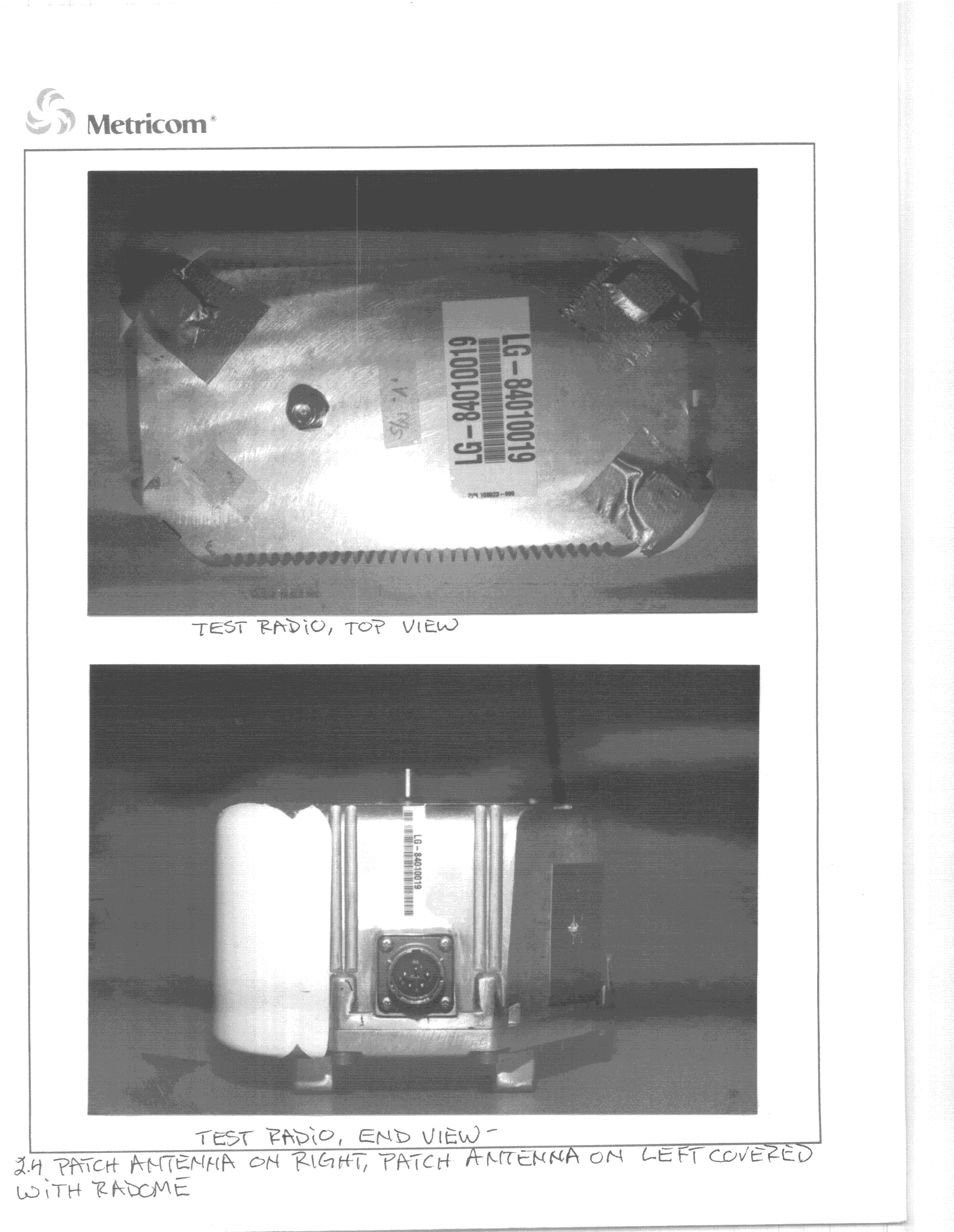
GNW24000
Jul 04, 2000DSS - Part 15 Spread Spectrum Transmitter
Equipment Class
DSS - Part 15 Spread Spectrum Transmitter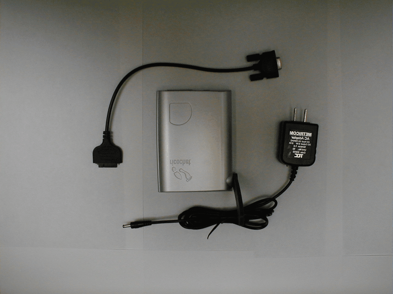
GNW22131
Jun 28, 2000Ricochet GT modem
Equipment Class
DSS - Part 15 Spread Spectrum Transmitter
GNW70000
May 17, 2000Metricom WCS WAP
Equipment Class
TNB - Licensed Non-Broadcast Station TransmitterGNW21071
Oct 01, 1997Industrial Communications Radio Maximum output power: 1 W This device must be professionally installed.
Equipment Class
DSS - Part 15 Spread Spectrum TransmitterGNW21022
Dec 16, 1996Data Radio Module Maximum output power: 1 Watt
Equipment Class
DSS - Part 15 Spread Spectrum Transmitter