GNW70000Metricom WCS WAP
Ricochet Networks, Inc.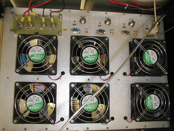
Click to zoom
Application Details
- Equipment Class
- TNB - Licensed Non-Broadcast Station Transmitter
- Date of Grant
- May 17, 2000
- Application Purpose
- Original Equipment
- Date of Application
- Jan 10, 2000
- Equipment Note
- Metricom WCS WAP
- Frequency Range
- 2345.76000000 - 2349.76000000
- Company
- Ricochet Networks, Inc.
- Country
- United States
Documents & Files
Document Text
Text extracted from the exhibit documents filed with the FCC. Open a document above to read the original.
Block Diagram
WCS WAP 4 Sector INDOOR Interconnect Power Distribution Modem Microwave Radio (optional) Cabletron 2200 Switch SNMP 6A 3A 25A -48V Return bus bar -48V bus bar #12 AWG E radio modem SNMP Cabletron 2200 microwave Code Switch #6 #8 #6 #8 #6 #6 #6 #6 #6 #6 #6 #6 #6 1/4 1/4 1/4 1/4 1/4 1/4 #4 lug #4 lug -48V Battery Tray Positive to Return BUS Negative to -48V BUS #4 lug 3A 3A 3A 3A 1/4 1/4 1/4 1/4 1/4 1/4 1/4 1/4 E radio E radio E radio Power Amp P / N DESCRIPTION PV18-6FF Flanged Fork terminal Vinyl Insulated,22-18 AWG PV18-8FF Flanged Fork terminal Vinyl Insulated,22-18 AWG PV18-14R Ring Terminal Vinyl Insulated,22-18 AWG PV10-6F Flanged Fork terminal Vinyl Insulated,12-10 AWG PV10-14R Ring Terminal Vinyl Insulated,12-10 AWG LCB4-14 Cooper Lug/Long Barrel One Hole 1/4, 4 AWG LCC4-14A Cooper Lug/Long Barrel Two Hole 1/4, 4 AWG #6 #8 #6 1/4 1/4 #4 lug #4 lug Terminals use Panduit crimp tool P/N CT-1550 Lugs use Panduit crimp tool P/N CT-720 with Die P/N CD-720-1 code switch inter cell bar inter cell bar 1/4 1/4 Reboot Switch Fans 1/4 Reboot switch #10 #10 #10#10 circuit breakers Fan Tray CirculatorCirculatorCirculatorCirculator Power AmplifierPower Amplifier E RadioE RadioE RadioE Radio Power AmplifierPower Amplifier 4Sector Transmitter Assy. #6#6#6#6#6#6#6#6 #10 #10 #4 lug 25A25A25A25A 100 AMP Power Supply #4 lug 4 ea. 208/240 VAC Single Phase 20-AMP service drops #4 lug -48V Battery Tray Positive to Return BUS Negative to -48V BUS #4 lug inter cell bar inter cell bar #4 lug -48V Battery Tray Positive to Return BUS Negative to -48V BUS #4 lug inter cell bar inter cell bar #4 lug -48V bus bar #4 lug 75A 1/4 100A #4 lug 100A 100A #4 lug #4 lug #4 lug #4 lug Battery tray 1 Battery tray 2 Battery tray 3 3A 1/4 3A 1/4 3A 1/4 3A 1/4 circuit breakers output 1/4 1/4 #4 lug #18 AWG #18 AWG #18 AWG #18 AWG #18 AWG #18 AWG #18 AWG #18 AWG #14 AWG #18 AWG #18 AWG #10 AWG #4 AWG #18 AWG #18 AWG #18 AWG #18 AWG #18 AWG #18 AWG #18 AWG #18 AWG #10 AWG #14 AWG #10 AWG #4 AWG #4 AWG #4 AWG #4 AWG #4 AWG #4 AWG #4 AWG #4 AWG #10 AWG #4 lug #14 #14
Block Diagram
RF IN ANT OUT RECEIVE N FEMALE N FEMALE N FEMALE RF IN ANT OUT RECEIVE N FEMALE N FEMALE N FEMALE RF IN ANT OUT RECEIVE N FEMALE N FEMALE N FEMALE RF IN ANT OUT RECEIVE N FEMALE N FEMALE N FEMALE Filters RF OUT RF IN N FEMALE N FEMALE AMP Control 9Pin D sub Female RF OUT RF IN N FEMALE N FEMALE AMP Control 9Pin D sub Female RF OUT RF IN N FEMALE N FEMALE AMP Control 9Pin D sub Female RF OUT RF IN N FEMALE N FEMALE AMP Control 9Pin D sub Female RF OUT SMA FEMALE E-NET RJ-45 AMP Control 9Pin D sub Female RF IN SMA FEMALE RF OUT SMA FEMALE E-NET RJ-45 AMP Control 9Pin D sub Female RF IN SMA FEMALE RF OUT SMA FEMALE E-NET RJ-45 AMP Control 9Pin D sub Female RF IN SMA FEMALE RF OUT SMA FEMALE E-NET RJ-45 AMP Control 9Pin D sub Female RF IN SMA FEMALE E Radios Power AMPS. DATA RF RF RF RF RF RF RF RF DATA DATA DATA RF RF RF RF E-NET RJ-45 2 3 4 6 1 5 7 8 9 10 11 12 13 14 15 16 17 18 19 20 21 22 23 24 T-1 port RJ-45 T-1 port RJ-45 T-1 port RJ-45 T-1 port RJ-45 COM port RJ-45 DATA DATA DATA DATA Router POTS Line RJ-11 Hand Set RJ-11 Serial Port 25 pin D sub Rack Mount Modem Control Port Manager RS 232 Ports RJ-11 12345678 Female Power Reboot Switch Screw Terminals 1 2 345 Control Port 9 pin D sub Male E-NET RJ-45 Serial Port 9 pin D sub SNMP Female Relay inputs Power supply Relay Outputs SA 25 adapter, SA 9 adapter and RJ11 cables supplied by WTI SA 9 SA-25 1 2 3 4 5 6 7 8 4 3 2 5 6 RJ45 RJ11 Cabletron CPM-800 Custom cable for Cabletron to CPM 800 connection WTI part # RJC-CTRON-15 1 8 1 6 SA-9M WTI RJ11 cable part # AC-5 (5') or AC-10 (10') Custom cable for Cabletron to CPM 800 connection WTI part # RJC-CTRON-15 WTI RJ11 cable part # AC-5 (5') or AC-10 (10') WTI RJ11 cable part # AC-5 (5') or AC-10 (10') CPM-800 RMM-288DC RPB+DC30 WAP,WCS,Data Distrabution WCS Cable Interconnect Drawing
External Photos
WCS RACK Top to bottom • 3 DARS Band reject filters • Power amplifier shelf, (1 PA installed, others removed to show detail inside the shelf, behind the PA’s) • 4 WCS Radios • Power Supply circuit breakers • Ethernet Hub • -48VDC supply Power Amp Shelf; Left is PA #1, Right is PA controller. 2PA #2 and #3 removed to show some detail in the back of the shelf where the PA’s plug into the shelf Rear view of one of the DARS band reject filters. Rear view of the Power amplifier “shelf” Rear view of the 4 WCS radios Rear view of the networking equipment and the power supply.
RF Exposure Info
Metricom, Inc. 980 University Avenue Los Gatos, CA, 93030 (Tel) 408-399-8200 (Fax) 408-354-1024 Federal Communications Commission Maximum Permissible Exposure Assessment for the Metricom WCS Wired Access Point In accordance with FCC REPORT AND ORDER 96-326 Adopted: August 1, 1996 Prepared by David Waitt Metricom, Inc. Background: Metricom has developed the second generation of its Microcellular Data Network (MCDN). In a broad sense this new network operates in a similar fashion to the current Metricom MCDN, (which is used to provide the Ricochet Wireless data service in the metropolitan areas of San Francisco, San Jose, Seattle and Washington D.C.) The most notable difference between the previous MCDN and the new MCDN is the speed of the network. The WCS WAP is used to transmit data to the network radios (FCC ID GNW24000) in the MCDN network. There are four separate transmitters in the WCS WAP, each transmitter will be connected to an antenna pointing in a different direction. IE:, North, East South and West. Since the RF fields will not be additive in this case, only one transmitter is used in the calculations. MPE Calculations. The operating environment for the WCS WAPS will be in controlled environments such as commercial building rooftops and commercial antenna structures where only authorized personnel have access. The definitions of controlled and uncontrolled environments are included below from the FCC Report and Order 96-326: B. Definitions of Controlled and Uncontrolled Environments 35. The 1992 ANSI/IEEE guidelines specify two sets of exposure limits based on the "environment" in which the exposure takes place. These environments are classified as either "controlled" or "uncontrolled." Controlled environments are defined as locations where "there is exposure that may be incurred by persons who are aware of the potential for exposure as a concomitant of employment, by other cognizant persons, or as the incidental result of transient passage through areas where analysis shows the exposure levels may be above [the exposure and induced current levels permitted for uncontrolled environment but not those permitted for controlled environments]." Uncontrolled environments are defined as "locations where there is the exposure of individuals who have no knowledge or control of their exposure. The exposures may occur in living quarters or workplaces where there are no expectations that the exposure levels may exceed [the exposure and induced current levels permitted for uncontrolled environments]." Duty Cycle correction: Even though the duty cycle of the WCS WAP source-based, to yield a worst case MPE distance, a duty cycle of 100 % is used in the following MPE calculations. From Part 2(d)(2) of the FCC Report and Order 96-326, General Rules and Regulations: (2) Time-averaging provisions may not be used in determining typical exposure levels for devices intended for use by consumers in general population/uncontrolled environments as defined in 1.1310 of this chapter. However, "source-based" time-averaging based on an inherent property or duty-cycle of a device is allowed. An example of this is the determination of exposure from a device that uses digital technology such as a time-division multiple-access (TDMA) scheme for transmission of a signal. In general, maximum average power levels must be used to determine compliance. Fixed, Occupational/Controlled Environment: Spec:2.3 GHz: 5.0 mW/cm 2 Exposure (mW/cm 2 ) = ( Pout (mW) *Duty Cycle*(Antenna Gain(as a ratio) / (4*PI* Radius 2 (cm)* Cable Loss * Filter Loss)) ) Solving the above for Radius Radius =Pout(mw)*Duty Cycle*(Antenna Gain(as a ratio, Rel to Isotropic) Exposure (mW/cm 2 ) * 4 * Pi * Cable Loss (ratio)* Filter Loss (ratio) 2.3 GHz MPE Distance Calculation: 50,000 * 1 * 63.095 3.1547 X10 6 149.828 cm MPE =5.0 * 4 * Pi * 1.584 * 1.412140.530 Distance MPE Distance: 5.20 feet. Conclusion: The WCS WAPS will be installed at commercial communication sites. Only professional communications systems workers will have access to these sites. Therefore, these individuals will be familiar with the hazards of RF exposure. Metricom will place “Notice” , “Warning” and “Caution” signs up at each site to warn workers that if they are within the MPE distance from the antenna and therefore their exposure may be exceeding the FCC’s guidelines. Table 1. Limits for Maximum Permissible Exposure (MPE) (A) Limits for Occupational/Controlled Exposure ______________________________________________________________________________ Frequency Electric Field Magnetic Field Range Strength Strength Power Density Averaging Time (MHz) (V/m) (A/m) (mW/cm2) (minutes) ______________________________________________________________________________ 0.3-3.0 614 1.63 (100)* 6 3.0-30 1842/f 4.89/f (900/f2)* 6 30-300 61.4 0.163 1.0 6 300-1500 -- -- f/300 6 1500-100,000 -- -- 5 6 ______________________________________________________________________________ f = frequency in MHz * = Plane-wave equivalent power density (B) Limits for General Population/Uncontrolled Exposure ______________________________________________________________________________ Frequency Electric Field Magnetic Field Range Strength Strength Power Density Averaging Time (MHz) (V/m) (A/m) (mW/cm2) (minutes) ______________________________________________________________________________ 0.3-1.34 614 1.63 (100)* 30 1.34-30 824/f 2.19/f (180/f2)* 30 30-300 27.5 0.073 0.2 30 300-1500 -- -- f/1500 30 1500-100,000 -- -- 1.0 30 ______________________________________________________________________________ f = frequency in MHz * = Plane-wave equivalent power density NOTE 1 TO TABLE 1: Occupational/controlled limits apply in situations in which persons are exposed as a consequence of their employment provided those persons are fully aware of the potential for exposure and can exercise control over their exposure. Limits for occupational/controlled exposure also apply in situations when an individual is transient t…
Text truncated - open the document above for the full version.
Test Report
Metricom, IncWCS WAP Type Acceptance ApplicationDec 1999 Metricom, Inc.Page #1 980 University Ave. Los Gatos, CA. 95032Tel: (408) 399-8200 wcs_wap_app.doc(dw8) Metricom, Inc. 980 University Avenue Los Gatos, CA, 93030 (Tel)408-399-8200 (Fax) 408-354-1024 FCC CFR 47, Part 27 Type Acceptance Application for Metricom, Inc. WCS Wired Access Point Prepared by: Metricom, Inc. 980 University Ave Los Gatos, CA. 95030 408-399-8200 Tested: December 1999 Metricom, IncWCS WAP Type Acceptance ApplicationDec 1999 Metricom, Inc.Page #2 980 University Ave. Los Gatos, CA. 95032Tel: (408) 399-8200 wcs_wap_app.doc(dw8) 1.0 Verification of Compliance Description:Metricom WCS Wired Access Point (WAP) Serial Number(s):Pre-production ”beta” Models, SN #0001 Applicant:Metricom Inc. Type of Test:FCC Part 27 Date(s) of test:December 1999 Tested ByDavid Waitt, Metricom, Los Gatos Juan Martinez, Compliance Certification Services The above equipment was tested by Metricom Inc. and Compliance Certification Services and found to be in compliance with the requirements set forth in Part 27 of the FCC rules and regulations governing WCS communications equipment. Metricom, IncWCS WAP Type Acceptance ApplicationDec 1999 Metricom, Inc.Page #3 980 University Ave. Los Gatos, CA. 95032Tel: (408) 399-8200 wcs_wap_app.doc(dw8) 2.0General Information Applicant:Metricom, Inc. 980 University Ave. Los Gatos, CA. 95030 Contact Person:David Waitt [email protected] (Tel) 408-399-8126 (Fax) 408-354-1024 Equipment Under Test:Metricom WCS Wired Access Point (WAP) Serial Number(s):0001 Type of Test:FCC Part 27 Reason for testing:Type Acceptance of new equipment Metricom has developed the second generation of its Microcellular Data Network (MCDN). This network is made up primarily of Microcells and Wired Access Points (WAPs). Brief description of Metricom’s Microcellular Data Network (MCDN) The MCDN Network is a wide-area wireless data network primarily using frequency- hopping spread-spectrum, packet data technology and Metricom’s patented mesh architecture. The new network operates within the Part 15 (902-928 MHz and 2.4–2.4835 GHz) and the WCS (2.3 GHz) portions of the spectrum. Microcells The largest part of the of the MCDN consists of shoebox-sized radio transceivers, also called microcells, which are typically mounted to street lights or utility poles. They are strategically placed every quarter to half mile in a checkerboard pattern over a geographic area. Each microcell employs hundreds of hopping channels in the 900 MHz and 2.4 GHz band. These microcells serve as repeaters between a user with a portable wireless modem and a Wired Access Point. For the UPLINK, the data is relayed from the modem, through a microcell to a ISM WAP. For the DOWNLINK, the microcell receives data from a WCS WAP and then relays it to the user. Wired Access Points (WAP) Within a large “cluster” of microcells Metricom installs Wired Access Points, or WAPS, which convert the between RF packets and the wired IP network backbone. Each WAP and its associated cluster of microcells can support thousands of subscribers. There are two kinds of WAPS, ISM and WCS. The ISM WAPS primarily receive data from the microcells (though they are also capable of transmitting if need be) and the WCS WAPS transmit (only, no receive) data to the microcells. The WCS WAP consists of 4 transmitter radios, 4 RF Power Amplifiers, 4 DARS band reject filters, some associated Class B, Part 15 networking equipment and a –48 VDC power supply. A basic block diagram is shown on the following page. The WCS WAPs are not frequency hopping like the microcells. Each RF “chain” within the WCS WAP is assigned a specific channel within Metricom’s licensed band of operation. And each of the 4 antennas at a WAP installation will be pointing in different directions. Metricom, IncWCS WAP Type Acceptance ApplicationDec 1999 Metricom, Inc.Page #4 980 University Ave. Los Gatos, CA. 95032Tel: (408) 399-8200 wcs_wap_app.doc(dw8) WCS WAP Basic Block Diagram RF Power Budget: PA Output:50 W (16.9 dBW) DARS Reject Filter passband Loss:1.5 dB Typical cable loss to antenna:2 dB Antenna Gain:18 dBi 16.9 dBW – 1.5 dB – 2 dB + 15.85 dBD = 29.25 dBW ERP = 841.4 Watts ERP DARS Band-Reject filter 50W HPA WCS Xmitter DARS Band-Reject filter 50W HPA WCS Xmitter DARS Band-Reject filter 50W HPA WCS Xmitter DARS Band-Reject filter 50W HPA WCS Xmitter "Off the shelf", Class B, networking equip. Ethernet switches, routers, hubs, etc . RFData To individual antennas -48VDC Power Supplies To: Networking Equipment, Transmitters and HPA's Metricom, IncWCS WAP Type Acceptance ApplicationDec 1999 Metricom, Inc.Page #5 980 University Ave. Los Gatos, CA. 95032Tel: (408) 399-8200 wcs_wap_app.doc(dw8) 3.0Results Summary The following test were performed to demonstrate compliance with FCC Part 27 Part 27 Paragraph Test Result 27.53 Out of Band Emissions (Radiated).62 dB in Spec 27.53 Out of Band Emissions (Conducted)5.3 dB in spec 27.54Frequency StabilityPass, 2.83kHz over temp 4.0 Test Facilities The radiated out of band emissions test was performed at: Compliance Certification Services 1366 Bordeoux Dr. Sunnyvale, CA 94089 (Morgan Hill OATS, Site ‘A’) A description of the sites located at Compliance Certification Services is on file at: Federal Communications Commission PO 429 Columbia, MD. 21045 All of the sites at Compliance Certification Services are constructed and calibrated to meet ANSI C63.4- 1994 requirements. The remaining tests described in this report were performed at: Metricom, Inc. 980 University Ave Los Gatos, CA. 95030 5.0Test Equipment & General Test Methods Equipment: The following test equipment was used to perform the testing Desc. Manufacturer Model Horn AntennaEMCO3115 Pre Amp(1-26.5GHz)HP8449B PlotterHP7470A 20 dB PadHPNA 30 dB Pad (150W)Narda Spectrum AnalyzerHP8566B 4.0 GHz HPFLaboratory GradeNA Diagnostic SoftwareMetricom, MFG_CMDSNA Spectrum AnalyzerHP Power MeterHP Power SensorHP HP = Hewlett Packard Method: M…
Text truncated - open the document above for the full version.
Test Report
Compliance Certification ServicesDate:11/5/99 Fcc 27.53(a3); ref: 2.1051Juan Martinez A-site (1 or 3 meters) Company:Metricom Model:4 Rack amplifier w/ radios, Power supply, filters. F(MHz)PKAVAFCLAMPDISTOTHERTOTALLIMITMARGIN dBuvdBuv(dB)(dB)(dB)(dB)(dB)(dBuV/m)(dBuV/m)(dBuV/m) PK AVPKAV fo= 2315 463050.434.14.71-350054.2155.23-1.02 6945(N.F.)31.835.65.250-20052.6555.23-2.58 9262(N.F.)36.1376-35-15.5028.655.23-26.63 11577(N.F.)35.739.57.5-35-15.5032.255.23-23.03 13893(N.F.)39.840.88.25-35-15.5038.3555.23-16.88 16208(N.F.)39.7399.3-35-15.5037.555.23-17.73 fo= 2319 463850.634.14.71-350054.4155.23-0.82 6957(N.F.)30.835.65.250-20051.6555.23-3.58 9276(N.F.)36.2376-35-15.5028.755.23-26.53 11595(N.F.)36.739.57.5-35-15.5033.255.23-22.03 13914(N.F.)38.940.88.25-35-15.5037.4555.23-17.78 16233(N.F.)40.1399.3-35-15.5037.955.23-17.33 fo= 2345 469050.834.14.71-350054.6155.23-0.62 703531.235.65.250-20052.0555.23-3.18 938036.4376-35-15.5028.955.23-26.33 1172537.239.57.5-35-15.5033.755.23-21.53 1407039.240.88.25-35-15.5037.7555.23-17.48 1641539.8399.3-35-15.5037.655.23-17.63 fo= 2350 470050.534.14.71-350054.3155.23-0.92 705032.135.65.250-20052.9555.23-2.28 940037.8376-35-15.5030.355.23-24.93 1175038.139.57.5-35-15.5034.655.23-20.63 1410038.440.88.25-35-15.5036.9555.23-18.28 1645039.4399.3-35-15.5037.255.23-18.03 DIST: Distance correction factor (.5METERS; -15.5dB)ANALYZER BANDWIDTH SETTINGS OTHER:High pass filter insertion loss (4GHz)Res Bw:Video Bw: AF: Antenna FactorDUTY: Duty Cycle correction factorPeak(Pk):1MHz1MHz AMP: Pre-amp gainCL: CABLE LOSSAvg(AV):1MHz10Hz N.F.: NOISE FLOOR MEASUREMENTS Additional notes: Section 27.53(a)(a3) states: The power of any emission outside the lincesee's frequency band(s) of operation shall be attenuated below the transmitt power (p), by a factor no less than 70 + 10 log (P) dB on all frequencies below 2300 MHz and on all frequencies above 2370 MHz. Using the relationship between field strength and RF power into an isotropic transmit antenna: E(V/m) = (30 * P * G)^1/2 D = Distance D(meters)G= Gain Numeric of antenna, assume 1 P= Power in Watts E(V/m) = (30 * 63 * 1)^1/2 = 14.49 V/m 3 meters 20 * log (14.49 * 1,000,000) = 143.22 dBuV/m @ 3 meters Part 27.53(a3): 70 + 10 log(63) = 87.99 dB 143.22 dBuV/m - 87.99 dB = 55.23 dBuV/m @ 3 meters
Test Report
Emissions Test Data Client: MetricomDate:8/10/99Test Engr:Chris Byleckie Product: WCS RackFile:T33175Proj. Engr:Chris Byleckie ObjectiveFinal QualificationSite:SVOATS #2Contact:David Waitt Spec:FCC Part 27Distance:10 mApproved: Power measurements were done with a spectrum analyzer EUT Rated Average Power:42Watts EUT Rated Peak Power:45Watts Run #1: Maximized radiated emissions, 30-2000 MHz Measurements done at 3m, all measured with RBW=1MHz, VBW=10Hz System on but not transmitting The only external cables were the AC line cables. Emission levels were not affected by maximizing these cables FrequencyLevelPolERPRel.LevelDetectorLimitMarginAzimuthHeight MHzdBuV/mv/hdBmdBcPk/AvgdBcdBdegreesmeters 30.00045.6v -51.998.1Avg86.2-11.9-1.0Note 1 60.00042.0v -55.5101.7Avg86.2-15.5-1.3 95.99830.2v -67.3113.5Avg86.2-27.3-1.0Note 2 192.00037.8v -59.7105.9Avg86.2-19.7-1.0 72.00040.0v -57.5103.7Avg86.2-17.5-1.0 216.00042.0v -55.5101.7Avg86.2-15.5-1.6 200.00046.1v -51.497.6Avg86.2-11.4-1.0 120.00037.6h-59.9106.1Avg86.2-19.9-1.6 200.00046.5h-51.097.2Avg86.2-11.0-4.0Note 2 312.00045.0v-52.598.7Avg86.2-12.5-1.0 560.31043.9v-53.699.8Avg86.2-13.6-1.0Note 2 319.98338.5h-59.0105.2Avg86.2-19.0-1.0Note 3 312.00049.3h-48.294.4Avg86.2-8.2-2.4 336.00044.5h-53.099.2Avg86.2-13.0-1.0 432.00042.3h-55.2101.4Avg86.2-15.2-1.0 1210.00037.7v -59.8106.0Avg86.2-19.8-1.0 Note 1:Broadband Noise Note 2:Signal Substitution Note 3:Signal + ambient Emissions Test Data Client: MetricomDate:8/10/99Test Engr:Chris Byleckie Product: WCS RackFile:T33175Proj. Engr:Chris Byleckie ObjectiveFinal QualificationSite:SVOATS #2Contact:David Waitt Spec:FCC Part 27Distance:10 mApproved: Run #2: Radiated emissions, 2000 - 24,000 MHz 3m, all measured with RBW=1MHz, VBW=10Hz Fundamental frequency = 2316.48 Mhz Full system, 3 radios transmitting. No preamp was used in the measurement system FrequencyLevelPolERPRel.LevelDetectorLimitMarginAzimuthHeight MHzdBuV/mv/hdBmdBcPk/AvgdBcdBdegreesmeters 2316.4886.2v-11.357.5AvgNo SpecNo Spec-- 4632.9676.7v-20.767.0Avg86.219.3--Note 1 Note 1:a quick look at the other harmonics showed the 3rd and 4th were probably out of spec also. Run #3: Radiated emissions, 2000 - 24,000 MHz 3m, all measured with RBW=1MHz, VBW=10Hz Fundamental frequency = 2316.48 Mhz Full system, 3 radios transmitting. No preamp was used in the measurement system FrequencyLevelPolERPRel.LevelDetectorLimitMarginAzimuthHeight MHzdBuV/mv/hdBmdBcPk/AvgdBcdBdegreesmeters 2316.4895.7v-1.848.0AvgNo SpecNo Spec-- 4632.9679.5v-18.064.2Avg86.222.1-- Run #4: Radiated emissions, 2000 - 24,000 MHz 3m, all measured with RBW=1MHz, VBW=10Hz Fundamental frequency = 2316.48 Mhz One radio, PA, filter transmitting. RF coax to 50 db Pad. No preamp was used in the measurement system FrequencyLevelPolERPRel.LevelDetectorLimitMarginAzimuthHeight MHzdBuV/mv/hdBmdBcPk/AvgdBcdBdegreesmeters 2316.4886.2v-11.357.5AvgNo SpecNo Spec-- 4632.9676.7v-20.767.0Avg86.219.3-- Emissions Test Data Client: MetricomDate:8/10/99Test Engr:Chris Byleckie Product: WCS RackFile:T33175Proj. Engr:Chris Byleckie ObjectiveFinal QualificationSite:SVOATS #2Contact:David Waitt Spec:FCC Part 27Distance:10 mApproved: Run #5: Radiated emissions, 2000 - 24,000 MHz 3m, all measured with RBW=1MHz, VBW=10Hz Fundamental frequency = 2316.48 Mhz One radio, PA. No filter. 50 dB pad connected to PA via .5m coax cable No preamp was used in the measurement system FrequencyLevelPolERPRel.LevelDetectorLimitMarginAzimuthHeight MHzdBuV/mv/hdBmdBcPk/AvgdBcdBdegreesmeters 2316.4885.8v-11.657.9AvgNo SpecNo Spec-- 4632.9677.2v-20.366.5Avg86.219.7-- Run #6: Radiated emissions, 2000 - 24,000 MHz 3m, all measured with RBW=1MHz, VBW=10Hz Fundamental frequency = 2316.48 Mhz Same as Run #4 except the 50dB pad was connected directly to the PA output. No preamp was used in the measurement system FrequencyLevelPolERPRel.LevelDetectorLimitMarginAzimuthHeight MHzdBuV/mv/hdBmdBcPk/AvgdBcdBdegreesmeters 2316.4885.8v-11.657.9AvgNo SpecNo Spec-- 4632.9676.1v-21.467.6Avg86.218.6-- Run #7: Radiated emissions, 2000 - 24,000 MHz 3m, all measured with RBW=1MHz, VBW=10Hz Fundamental frequency = 2316.48 Mhz Radio only. Radio output was terminated in 30dB pad and a 50 ohm load The preamp was used in the measurement system. FrequencyLevelPolERPRel.LevelDetectorLimitMarginAzimuthHeight MHzdBuV/mv/hdBmdBcPk/AvgdBcdBdegreesmeters 2316.4845.8v-51.797.9AvgNo SpecNo Spec-- 4632.9617.0v-80.5126.7Avg86.2-40.5-- Run #8: Conducted measurements to verify radio / PA / filter chain performance. 2nd harmonic was suppressed approx. 50 dB out of the PA. 2nd harmonic was suppressed approx. 65 dB with the addition of the filter at the PA output Run #9: Troubleshooting Near field probing was done to try and isolate the 2nd harmonic leakage. The signal was strong all around the enclosure, inside and out. The maximum signal level was found to be at the front on the power amp, where a ribbon cable was running betweeen the two sections of the PA.
Test Report
GNW7000 WCS Radio Frequency Stability Data, -30 to + 50 C The unit was placed in a temperature chamber and the temperature of the chamber lowered to –30C. The temperature of the radios was allowed to stabilize. Once the temperature had stabilized, the center frequency of several channels (at the edge of the bands) was measured and one of the channels was monitored with a spectrum analyzer on MAX HOLD. The temperature of the chamber was then raised to +50 C and the temperature of the radios allowed to stabilize. The frequencies of the channels was then measured again and compared to the first reading. In the case of the channel that was monitored with the spectrum analyzer during the temperature change, the maximum drift could be read off the spectrum analyzer. The amount of drift of the other channels matched the drift measured by the spectrum analyzer using MAX HOLD. Therefore, all of the channels in the radio drifted the same amount and in the same direction, as excepted. The drift data is summarized below. Channel Center Freq(MHz) Occ BW (MHz) Max Drift -30 to + 50 (MHz) Channel edge w/ Drift WCS Band edge Delta (MHz) 2315.2 0.32 0.00558 2315.03442 2315 0.03442 2319.36 0.32 0.00558 2319.52558 2320 0.47442 2345.76 0.32 0.00558 2345.59442 2345 0.59442 2349.76 0.32 0.00558 2349.92558 2350 0.07442 Even though the drift was always from a higher frequency to a lower one, in the case of the channels at 2319.36 MHz and 2349.76MHz, a drift in the opposite direction was assumed in order to yield a worst case result (That would be the drift moving closer to the band edge when in reality the drift would cause the radio to drift away from the band edge. WCS Radio Emission Designation: The WCS radio will use two modulations in the field. The two modulations are: QPSK and 16QAM w/ Trellis coding. The modulation used will be selected by the radio automatically depending on what modulation the radio determines communication link can reliabily support. For example, if the link has been unreliable and packets have had to be retransmitted , then the more robust (but slower) QPSK would be used. If the link has proven to be reliable in the past,the radio may select the faster 16 QAM modulation. Therefore there are two Emission designators for the WCS radios. 16QAM w. Trellis Coding: 320kD1D QPSK: 320kG1D Freq (-30C) Freq (+50C) Delta, 5.58 kHz Drift Upper Band Edge Actual DriftAssumed Drift Upper Channel Center Freq
Contact Information
Applicant
Kathy Eberhart(Paralegal)
Technical Contact
Metricom Incdavid waitt
[email protected]408039908126
980 university ave · los gatos, California · United States
Non-Technical Contact
metricom Incdavid waitt
[email protected]4083998126
Technical Specifications
| # | Rule Parts | Frequency Range | Power Output | Emission | Tolerance |
|---|---|---|---|---|---|
| 4 | 27 | 2.35 GHz - 2.35 GHz | 22.38 W | 320KG1D | 2830 Hz |
Other Applications from Ricochet Networks, Inc.
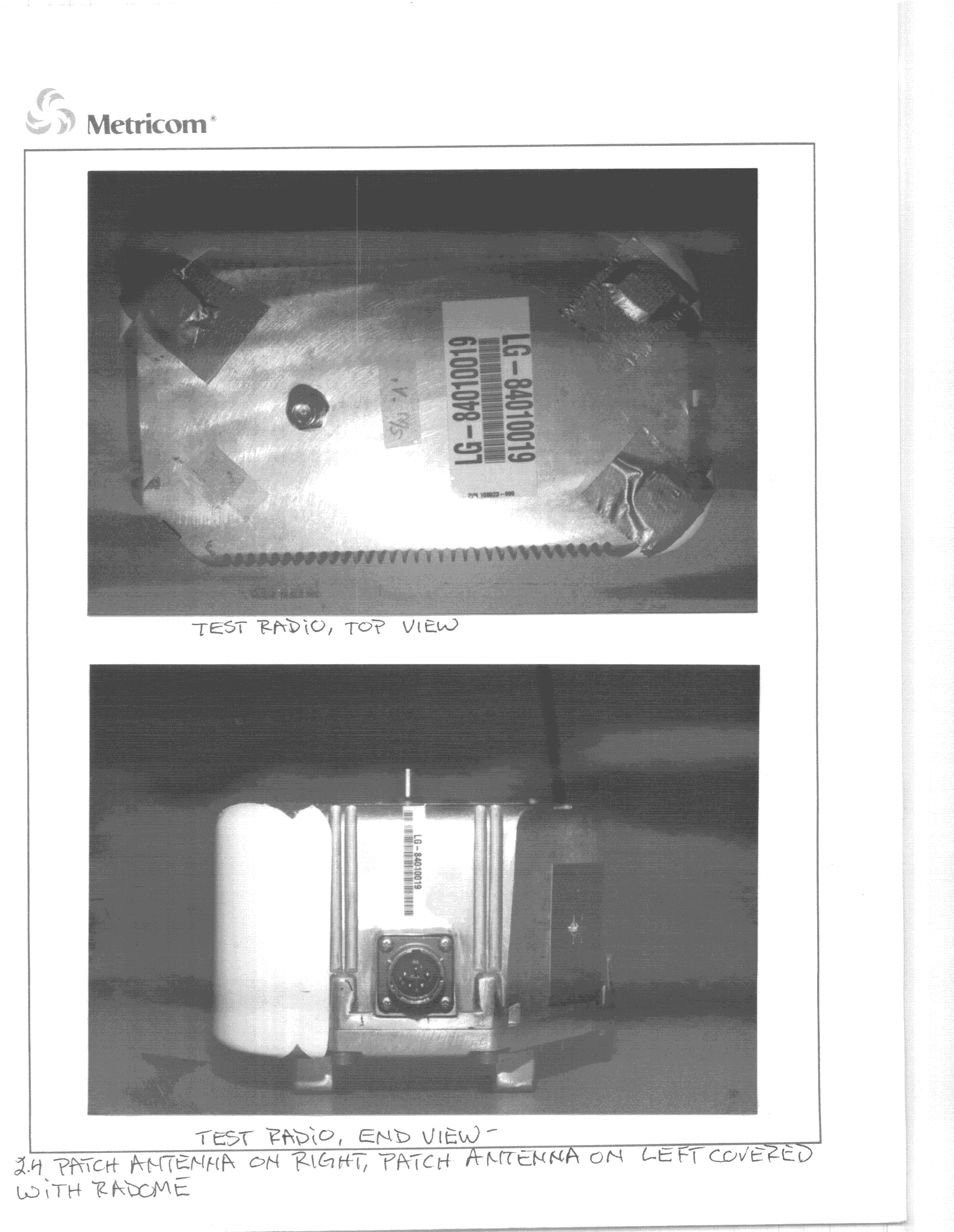
GNW24000
Jul 04, 2000DSS - Part 15 Spread Spectrum Transmitter
Equipment Class
DSS - Part 15 Spread Spectrum Transmitter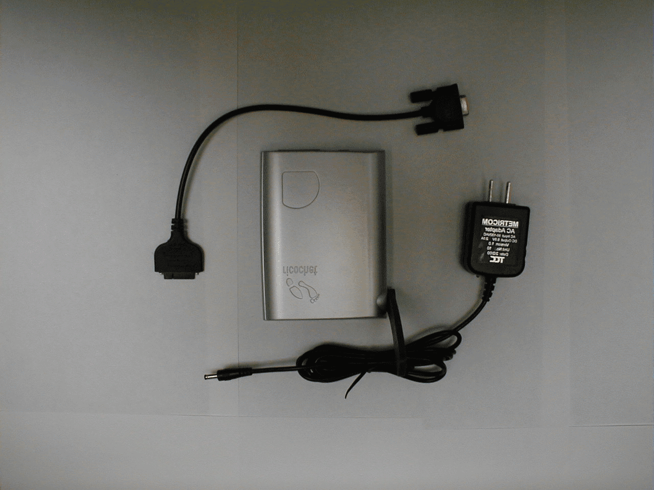
GNW22131
Jun 28, 2000Ricochet GT modem
Equipment Class
DSS - Part 15 Spread Spectrum Transmitter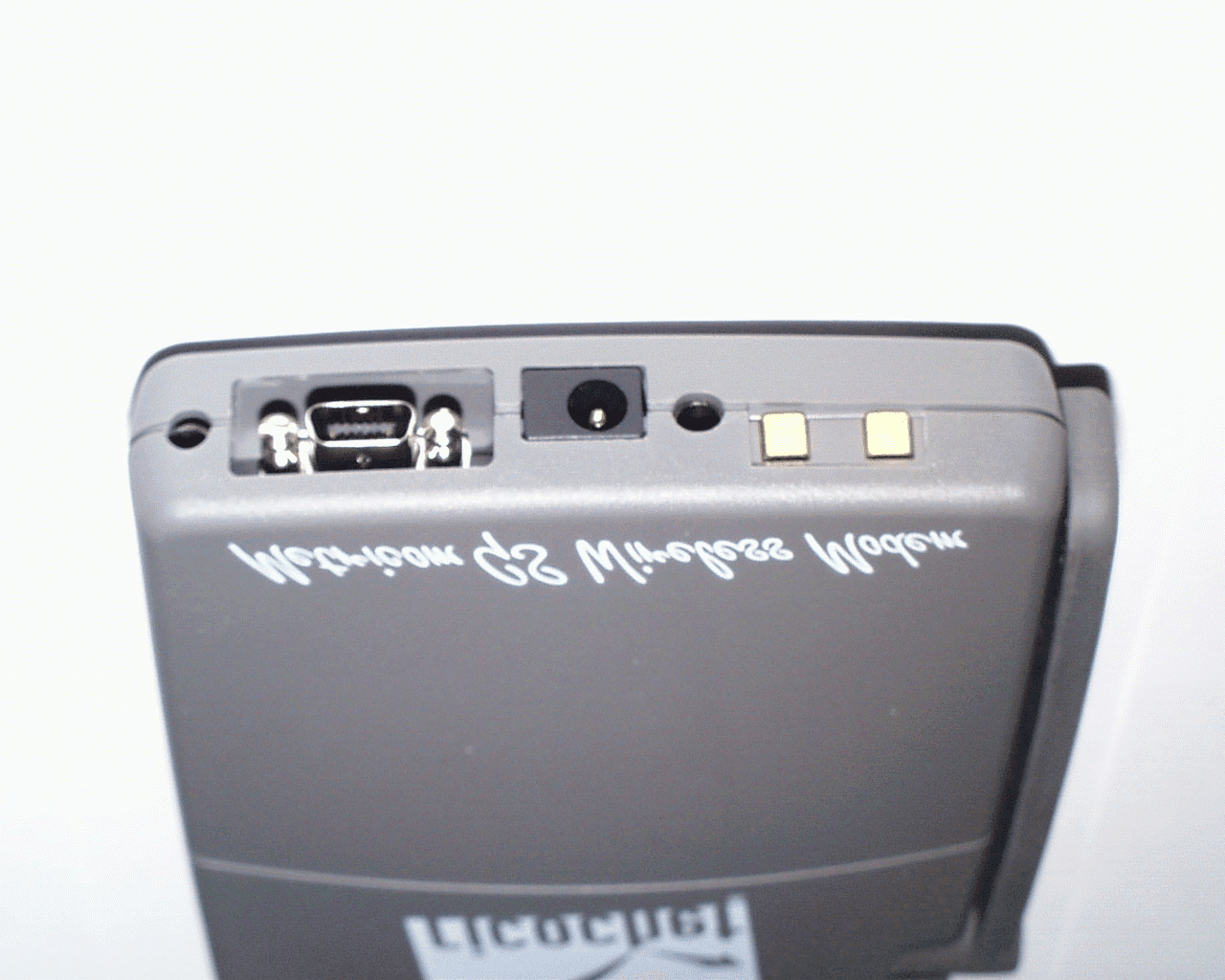
GNW21100
Mar 05, 2000Ricochet GS wireless Modem
Equipment Class
DSS - Part 15 Spread Spectrum TransmitterGNW21071
Oct 01, 1997Industrial Communications Radio Maximum output power: 1 W This device must be professionally installed.
Equipment Class
DSS - Part 15 Spread Spectrum TransmitterGNW21022
Dec 16, 1996Data Radio Module Maximum output power: 1 Watt
Equipment Class
DSS - Part 15 Spread Spectrum Transmitter