GNW24000
Ricochet Networks, Inc.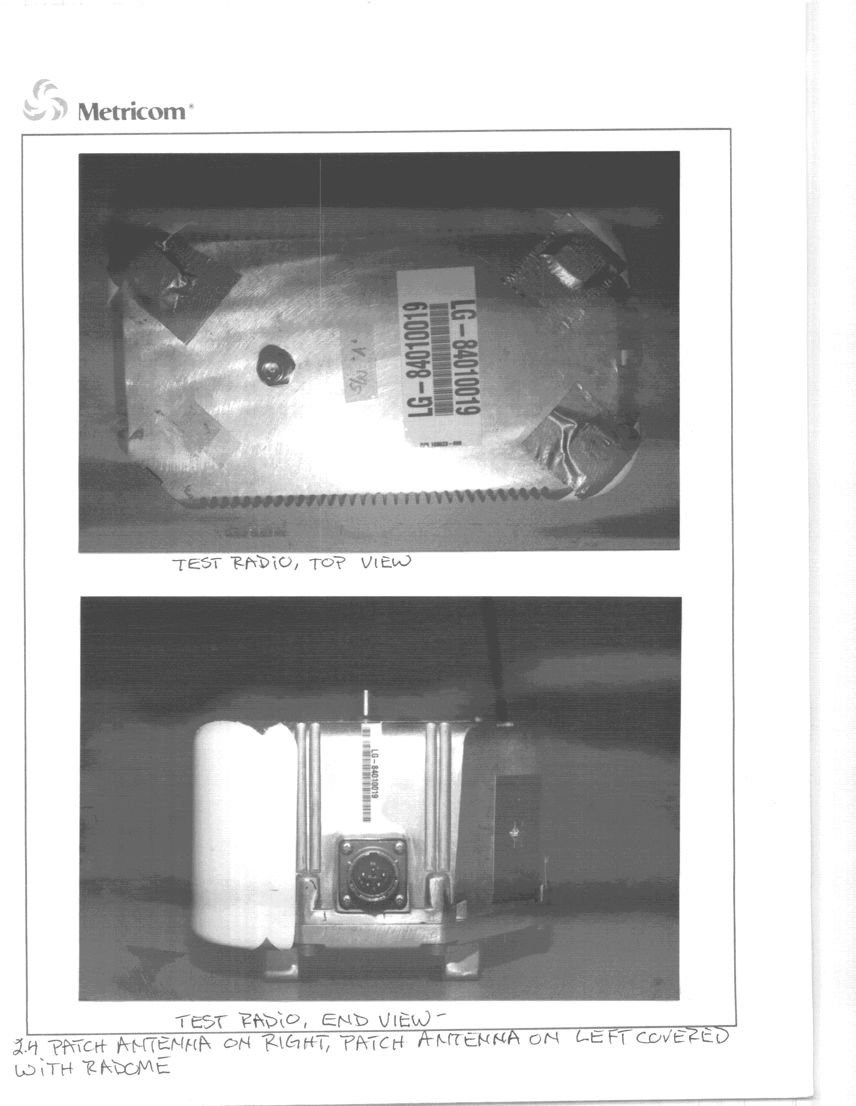
Click to zoom
Application Details
- Equipment Class
- DSS - Part 15 Spread Spectrum Transmitter
- Date of Grant
- Jul 04, 2000
- Application Purpose
- Original Equipment
- Date of Application
- Feb 01, 1999
- Frequency Range
- 2400.32000000 - 2483.20000000
- Company
- Ricochet Networks, Inc.
- Country
- United States
Documents & Files
Document Text
Text extracted from the exhibit documents filed with the FCC. Open a document above to read the original.
RF Exposure Info
Metricom, Inc. 980 University Avenue Los Gatos, CA, 93030 (Tel) 408-399-8200 (Fax) 408-354-1024 Federal Communications Commission Maximum Permissible Exposure Assessment for the Metricom Ethernet Radio, GNW 24000 In accordance with FCC REPORT AND ORDER 96-326 Adopted: August 1, 1996 Prepared by David Waitt Metricom, Inc. Background: Metricom has developed the second generation of its Microcellular Data Network (MCDN). In a broad sense this new network operates in a similar fashion to the current Metricom MCDN, (which is used to provide the Ricochet Wireless data service in the metropolitan areas of San Francisco, San Jose, Seattle and Washington D.C.) The most notable difference between the previous MCDN and the new MCDN is the speed of the network. The network radio is a frequency hopping spread spectrum radio that operates within the 902-928 MHz and the 2.4–2.4835 MHz band. The peak transmit output power of the radio is 1 Watt on each band. The radio is capable of communicating with either Micro-Cellular Data Network (MCDN) microcell radios (GNW 21000) that make up the infrastructure of the MCDN network or Ricochet modems. MPE Calculations. The operating environment for the network radio (the top of a utility pole or streetlight) is a fixed, controlled environment. It is reasonable to assume that professional linesmen who work on utility poles and utility workers who work on streetlights will be aware, via their training, of the hazards of RF exposure. However, to yield a worst case analysis, the limits for an uncontrolled environment are used in this document. The definitions of controlled and uncontrolled environments are included below from the FCC Report and Order 96-326: B. Definitions of Controlled and Uncontrolled Environments 35. The 1992 ANSI/IEEE guidelines specify two sets of exposure limits based on the "environment" in which the exposure takes place. These environments are classified as either "controlled" or "uncontrolled." Controlled environments are defined as locations where "there is exposure that may be incurred by persons who are aware of the potential for exposure as a concomitant of employment, by other cognizant persons, or as the incidental result of transient passage through areas where analysis shows the exposure levels may be above [the exposure and induced current levels permitted for uncontrolled environment but not those permitted for controlled environments]." Uncontrolled environments are defined as "locations where there is the exposure of individuals who have no knowledge or control of their exposure. The exposures may occur in living quarters or workplaces where there are no expectations that the exposure levels may exceed [the exposure and induced current levels permitted for uncontrolled environments]." Duty Cycle correction: Even though the duty cycle of the MCDN Network radio is source-based, to yield a worst case MPE distance, a duty cycle of 100 % is used in the following MPE calculations. From Part 2(d)(2) of the FCC Report and Order 96-326, General Rules and Regulations: (2) Time-averaging provisions may not be used in determining typical exposure levels for devices intended for use by consumers in general population/uncontrolled environments as defined in 1.1310 of this chapter. However, "source-based" time-averaging based on an inherent property or duty-cycle of a device is allowed. An example of this is the determination of exposure from a device that uses digital technology such as a time-division multiple-access (TDMA) scheme for transmission of a signal. In general, maximum average power levels must be used to determine compliance. Fixed, Uncontrolled Environment: Spec:900 MHz: f(MHz)/1500 mW/cm 2 = 902/1500 = .601 mW/cm 2 2.4 GHz: 1.0 mW/cm 2 Exposure (mW/cm 2 ) = Pout (mW)*Duty Cycle*(Antenna Gain(as a ratio)/(4*PI* Radius 2 (cm) ) ) Solving the above for Radius, General MPE Calculation Radius =Pout(mw)*Duty Cycle*(Antenna Gain(as a ratio) Exposure (mW/cm 2 ) * 4 * Pi MPE Calculation for two bands Radius =(900MHzP(mw)*900MHzAnt Gain(ratio))+(2.4GHzP(mw)*2.4GHzAnt Gain(ratio))* Duty Cycle Exposure (mW/cm 2 ) * 4 * Pi Radius = (900MHz EIRP(mw)+ 2.4GHz EIRP(mw))* Duty Cycle Exposure (mW/cm 2 ) * 4 * Pi Radius = (Total EIRP (mw))* Duty Cycle Exposure (mW/cm 2 ) * 4 * Pi 2.4 GHz EIRP: 2.4 GHzEIRP = Pout(dBm) + Antenna Gain (dBi) 27 dBm + 15 dBi = 42 dBm EIRP = 15848 mWatts EIRP 900 MHz EIRP EIRP = Pout(dBm) + Antenna Gain (dBi) 30 dBm + 6 dBi = 36 dBm EIRP = 4000 mWatts EIRP Total Watts EIRP 15848 mw EIRP + 4000 mw EIRP = 19848 mWatts EIRP 900MHz & 2.4 GHz Combined MPE Distance Calculation: (Note: The specification used in the calculation below is 900MHz specification, the lower of the two.) 19848mW * 1.019848 51.27 cm MPE =.601 * 4 * Pi7.55 Distance MPE =20.18 Inches Distance Conclusion: The MCDN Ethernet radios are to be located on the top of commercial rooftops, most likley with other RF transmitting equipment. Metricom personal installing the equipment will be made aware of the dangers of RF exposure via the Metricom Health and Safety program. As part of the Ethernet radio installation, signs warning of the dangers of RF radiation exposure will be installed to alert people who may have access to the rooftop of the danger. Exposure Limits from FCC96-326 Report and Order, Appendix C, Final Rules is given below. Table 1. Limits for Maximum Permissible Exposure (MPE) (A) Limits for Occupational/Controlled Exposure ______________________________________________________________________________ Frequency Electric Field Magnetic Field Range Strength Strength Power Density Averaging Time (MHz) (V/m) (A/m) (mW/cm2) (minutes) ______________________________________________________________________________ 0.3-3.0 614 1.63 (100)* 6 3.0-30 1842/f 4.89/f (900/f2)* 6 30-300 61.4 0.163 1.0 6 300-1500 -- -- f/300 6 1500-100,000 -- -- 5 6 ______________________________________________________________________________ f = frequency in MHz * = Plane-wave equi…
Text truncated - open the document above for the full version.
RF Exposure Info
Metricom, Inc. 980 University Avenue Los Gatos, CA, 93030 (Tel) 408-399-8200 (Fax) 408-354-1024 Federal Communications Commission Maximum Permissible Exposure Assessment for the Metricom Network Radio, GNW 24000 In accordance with FCC REPORT AND ORDER 96-326 Adopted: August 1, 1996 Prepared by David Waitt Metricom, Inc. Background: Metricom has developed the second generation of its Microcellular Data Network (MCDN). In a broad sense this new network operates in a similar fashion to the current Metricom MCDN, (which is used to provide the Ricochet Wireless data service in the metropolitan areas of San Francisco, San Jose, Seattle and Washington D.C.) The most notable difference between the previous MCDN and the new MCDN is the speed of the network. The network radio is a frequency hopping spread spectrum radio that operates within the 902-928 MHz and the 2.4–2.4835 MHz band. The peak transmit output power of the radio is 1 Watt on each band. The radio is capable of communicating with either Micro-Cellular Data Network (MCDN) microcell radios (GNW 21000) that make up the infrastructure of the MCDN network or Ricochet modems. MPE Calculations. The operating environment for the network radio (the top of a utility pole or streetlight) is a fixed, controlled environment. It is reasonable to assume that professional linesmen who work on utility poles and utility workers who work on streetlights will be aware, via their training, of the hazards of RF exposure. However, to yield a worst case analysis, the limits for an uncontrolled environment are used in this document. The definitions of controlled and uncontrolled environments are included below from the FCC Report and Order 96-326: B. Definitions of Controlled and Uncontrolled Environments 35. The 1992 ANSI/IEEE guidelines specify two sets of exposure limits based on the "environment" in which the exposure takes place. These environments are classified as either "controlled" or "uncontrolled." Controlled environments are defined as locations where "there is exposure that may be incurred by persons who are aware of the potential for exposure as a concomitant of employment, by other cognizant persons, or as the incidental result of transient passage through areas where analysis shows the exposure levels may be above [the exposure and induced current levels permitted for uncontrolled environment but not those permitted for controlled environments]." Uncontrolled environments are defined as "locations where there is the exposure of individuals who have no knowledge or control of their exposure. The exposures may occur in living quarters or workplaces where there are no expectations that the exposure levels may exceed [the exposure and induced current levels permitted for uncontrolled environments]." Duty Cycle correction: Even though the duty cycle of the MCDN Network radio is source-based, to yield a worst case MPE distance, a duty cycle of 100 % is used in the following MPE calculations. From Part 2(d)(2) of the FCC Report and Order 96-326, General Rules and Regulations: (2) Time-averaging provisions may not be used in determining typical exposure levels for devices intended for use by consumers in general population/uncontrolled environments as defined in 1.1310 of this chapter. However, "source-based" time-averaging based on an inherent property or duty-cycle of a device is allowed. An example of this is the determination of exposure from a device that uses digital technology such as a time-division multiple-access (TDMA) scheme for transmission of a signal. In general, maximum average power levels must be used to determine compliance. Fixed, Uncontrolled Environment: Spec:900 MHz: f(MHz)/1500 mW/cm 2 = 902/1500 = .601 mW/cm 2 2.4 GHz: 1.0 mW/cm 2 Exposure (mW/cm 2 ) = Pout (mW)*Duty Cycle*(Antenna Gain(as a ratio)/(4*PI* Radius 2 (cm) ) ) Solving the above for Radius, General MPE Calculation Radius =Pout(mw)*Duty Cycle*(Antenna Gain(as a ratio) Exposure (mW/cm 2 ) * 4 * Pi MPE Calculation for two bands Radius =(900MHzP(mw)*900MHzAnt Gain(ratio))+(900MHzP(mw)*900MHzAnt Gain(ratio))* Duty Cycle Exposure (mW/cm 2 ) * 4 * Pi Radius = (900MHz EIRP(mw)+ 2.4GHz EIRP(mw))* Duty Cycle Exposure (mW/cm 2 ) * 4 * Pi Radius = (Total EIRP (mw))* Duty Cycle Exposure (mW/cm 2 ) * 4 * Pi 2.4 GHz EIRP: EIRP = Pout(dBm) + Antenna Gain (dBi) 29 dBm + 8 dBi = 37dBm EIRP = 5011 mWatts EIRP 900 MHz EIRP EIRP = Pout(dBm) + Antenna Gain (dBi) 30 dBm + 6 dBi = 36 dBm EIRP = 4000 mWatts EIRP Total Watts EIRP 5011 mW EIRP + 4000 mW EIRP = 9011 mWatts EIRP 900MHz & 2.4 GHz Combined MPE Distance Calculation: (Note: The specification used in the calculation below is 900MHz specification, the lower of the two.) 9011mw * 1.09011 34.54 cm MPE =.601 * 4 * Pi7.552 Distance MPE =13.6 Inches Distance Conclusion: The MCDN network radios are to be located at, or near the top of telephone poles and streetlights. Given this location, the only personnel that will likely come within the MPE distance of the radio will be trained professional utility workers. These workers may be contracted by Metricom to replace or install a radio, or they may be contracted by the city in witch the pole is located to perform maintenance or repair on the utility pole or streetlight. It is safe to assume that these individuals will be familiar with the hazards of RF exposure. However, to be certain that no worker is exposed to levels of RF above the guidelines, Metricom will make the municipality in which the radio is installed aware, in writing, of these exposure issues such that the municipality can pass the information on to whomever they contract to work on the poles. With regards to contractors hired by Metricom, Metricom will modify the radio installation guide to warn about RF exposure. Exposure Limits from FCC96-326 Report and Order, Appendix C, Final Rules is given below. Table 1. Limits for Maximum Permissible Exposure (MPE) (A) Limits for Occupational/Controlled Exposure ______________________…
Text truncated - open the document above for the full version.
RF Exposure Info
Lock-Out/Tag-Out Protocols April 1999 METRICOM file: Section VI Page -17 Prepared for Metricom 16801 Greenspoint Park Dr., Suite 150 Houston, TX 77060 April 1999 METRICOM HEALTH AND SAFETY PROGRAM FOR EXPOSURE TO RADIO FREQUENCY RADIATION Argent Consulting Services, Inc. 11999 Katy Freeway, Suite 590 Houston, TX 77079 Lock-Out/Tag-Out Protocols April 1999 METRICOM file: Section VI Page -18 Project #2172 TABLE OF CONTENTS I. ..............................INTRODUCTION AND PURPOSE OF THE PROGRAM1 II. .........................................................SAFETY POLICY2 III. .....................................SAFETY OFFICER’S RESPONSIBILITIES4 IV. .......................DESCRIPTION OF THE RFR HEALTH AND SAFETY PROGRAM5 1.Utilization of installed RFR transmitters which meet applicable RFR and other safety standards during the time of use, including after any modifications5 2. RFR hazard identification and periodic surveillance.................5 3. Implementation of controls to insure RFR exposure levels are in compliance with applicable guidelines.................................................6 a.ADMINISTRATIVE CONTROLS...........................................6 b.SIGNS.............................................................6 c.RESTRICTED AREAS..................................................8 d. ENGINEERING CONTROLS..............................................8 i.RFR Monitors...............................................8 ii.RFR Survey Equipment.......................................9 e.WORK PROCEDURES...................................................9 f.RFR SAFETY AND HEALTH TRAINING...................................13 g.EMPLOYEE/TECHNICIAN/CONTRACTOR INVOLVEMENT.......................14 h.MEDICAL SURVEILLANCE PROGRAM AND FIRST AID FOR EXPOSURE TO EXCESSIVE RF RADIATION...........................................14 i.HAZARD ASSESSMENT................................................15 j.NON-ROUTINE TASKS................................................15 k.PROGRAM REVIEW...................................................15 l. COMPLIANCE.......................................................15 V. OSHA 29 CFR 1910.268: TELECOMMUNICATION STANDARDS.................16 LIST OF ENCLOSURES Enclosure 1.RFR “ Safety Program Guidelines” Sign Enclosure 2.RFR “Notice” Sign Enclosure 3.RFR “Caution” Sign Enclosure 4.RFR “Warning” Sign Enclosure 5.47 CFR Reference Enclosure 6.Lock-out/Tag-out Program Enclosure 7.Safety Inspection Checklist Enclosure 8.Maximum Permissible Exposure (MPE) Evaluations Lock-Out/Tag-Out Protocols April 1999 METRICOM file: Section VI Page -19 METRICOM SECTION I. I.INTRODUCTION AND PURPOSE OF THE PROGRAM As directed by the 1996 Telecommunications Act, the Federal Communications Commission (FCC) has revised guidelines for human exposure to RFR (Radio Frequency Radiation). The FCC adopted as their standard a combination of the ANSI/IEEE C95.1- 1992 and NCRP 1986 standards. This FCC standard is both preventative and precautionary in nature and applies to both “Controlled/Occupational” and “Uncontrolled/General Population” exposures of individuals- as defined in the FCC’s OET Bulletin No. 65. This safety program addresses the tower and rooftop antenna cell sites of METRICOM. The guidelines incorporated into the safety program will assist METRICOM employees, technicians, contractors, and consultants working in a “Controlled/Occupational” environment and the public in a “Uncontrolled/General Population environment in complying with RFR maximum permissible exposure (MPE) standards. Lock-Out/Tag-Out Protocols April 1999 METRICOM file: Section VI Page -20 METRICOM SECTION II. II. SAFETY POLICY In order to minimize the risk of overexposure to any individuals, it is the policy of METRICOM to: 1. Identify and control by engineering design, protective equipment, or administrative actions, hazardous RFR and other dangers associated with each antenna tower and/or roof-top antenna site and accompanying electronic equipment. This policy shall be adhered to during all phases of equipment design, acquisition, installation, operation, and maintenance. 2. Limit METRICOM and their customers’ employees, technicians, contractors and consultants exposure to RFR levels that are within the applicable MPE limits. 3. Assume maximum RFR exposure to individuals from all RF sources may exceed the MPE limits, and control exposure appropriately. 4. Ensure that individuals are aware of potential RFR at the METRICOM antenna tower sites and/or rooftop antenna sites and the control measures implemented to limit their exposure to RFR. Only authorized personnel are allowed entrance to the tower sites or rooftop sites. 5. Investigate and document all alleged RFR overexposure incidents. 6. Mandate that all employees, technicians, contractors, and consultants performing work or that enter the antenna tower sites and/or antenna roof-top sites for METRICOM or customers of METRICOM be required to sign a form prior to or upon entering the controlled area stating that: a.They have received and understand RFR awareness training. b. They understand how the RFR personal monitor works and why they are required to wear it. c. They are aware of the potential effects on medical implants and those individuals implanted with such devices enter the restricted area at their own risk. 7. Mandate that all employees, technicians, contractors, and consultants accessing the antenna tower sites and/or antenna roof-top sites for METRICOM or customers of METRICOM will: Lock-Out/Tag-Out Protocols April 1999 METRICOM file: Section VI Page -21 a. Report any encountered RFR effects to METRICOM. b.Test the RFR personal monitor according to manufacturer’s test procedures before and after usage to verify the RFR personal monitor was operating properly throughout the period that it was worn. c.Use the RFR personal monitor and employ the monitor with switch in “On” position during the period that they are in the controlled area. 8. The prov…
Text truncated - open the document above for the full version.
RF Exposure Info
Errol, Below is your latest comments and concerns regarding GNW-24000 ( EA93236) with Metricom’s reply and comments. Please let me know if there is anything else you require. David Waitt 408 399 8126 [email protected] ======================================================================= To:David Waitt, From:Errol Chang [email protected] FCC Application Processing Branch Re:FCC ID GNW24000 Applicant:Metricom Incorporated Correspondence Reference Number:10100 731 Confirmation Number:EA93236 Date of Original E-Mail:10/12/1999 1. The revised 731 form is indicating 794 mW output for the Network Radio operating at 2.4 GHz. The measured output data submitted around August 99 was showing 416-467 mW for the Network Radio at 2.4 GHz, therefore, 467 or 470 mW will be what the data can support. <METRICOM> Metricom will repeat the applicable tests on a network radio that has a higher transmit power and submit a permissive change request in the very near future. Until that time, the transmit power level stated above is acceptable. 2. Item #5 of previous correspondence - final version of installation instruction to be provided, please submit info. <METRICOM> It has become apparent that Metricom does not have an “Antenna Installation Guide” due to the fact that the installation of the Ethernet radio antennas at the Wired Access Points (WAPS) is a little different at each installation. (When I offered this document, I spoke to soon and offered something Metricom does not have.) Some of the antennas are hung over the front of a façade on the building rooftop others are mounted on poles secured to the roof in some manner, others are installed on communications towers which makes a What Metricom has done is to add a reference to Metricom’s Health and Safety plan for instructions as to what signs to place at the site and where to place them. The edited page is included in this document. Again, EVERYONE, who has access Metricom equipment at a WAP site will be made aware of the dangers of RF exposure as outlined in Metricom’s Health and Safety plan. The people installing the WAPS will be directed to installs the warning, caution and Danger signs as outlined in the Metricom Health and safety document. 3. Appropriate grant conditions for ensuring RF exposure compliance will be included, according to proposed conditions and installation instructions (to be provided). <METRICOM> See comments below regarding the proposed statement. 4. (FYI) In the future, please follow procedures similar to section 2 of 97-01 edition of OET Bulletin 65 (around page 35) to determine MPE compliance for multiple or co-locating transmitting sources. NOTE: As indicated in item #3 above the language similar to that given below will be placed on the grant following conditions will be placed on the grant. These conditions is based on Metricom's commitment up to this point and may change to reflect anything new. "This device includes Network Radio (NR) and Ethernet Radio (ER). NRs are for utility pole- mount only. ERs are for installation at the top of non-residential buildings and structures. Employees, contractors and consultants of Metricom must receive proper training to satisfy MPE requirements before gaining access to any active NR and ER. Metricom must inform all responsibility parties in writing to ensure persons gaining access to NR sites are required to maintain a minimum separation distance of 34.5 cm from active NR antennas to meet MPE requirements. RF exposure warning signs showing a minimum separation distance of 51 cm must be posted at access points to ER antennas; when ER antennas are co-located with other radio-frequency transmitting sources, the warning signs must include separation distances appropriate for meeting MPE requirements based on worst-case RF exposure conditions resulted from all RF transmitting sources located at the particular site." <METRICOM> Metricom feels that the wording of the statement above should be modified. The last sentence states: “RF exposure warning signs showing a minimum separation distance of 51 cm must be posted at access points to ER antennas; when ER antennas are co-located with other radio-frequency transmitting sources, the warning signs must include separation distances appropriate for meeting MPE requirements based on worst-case RF exposure conditions resulted from all RF transmitting sources located at the particular site." Metricom feels that it cannot comply with this statement. The Ethernet radios are installed as part of a Wired Access Point (WAP) installation. WAPs are installed on commercial building rooftops and on commercial communications towers. These types of communications sites typically have several antennas (paging transmitters, cell sites, amateur radio repeaters...) that are not under Metricom’s control and about which Metricom has no technical information. Therefore it is not possible for Metricom to install signs specifying a MPE distance for ALL of the transmitting sources at a particular site. Further, if Metricom were to install Ethernet radios at a site where no other communications equipment was present at the time of the installation and place signs stating a MPE distance at the access point to the site, the MPE distance on the sign would no longer be valid once additional communications equipment was placed at the site. Metricom advocates placing (OSHA approved) warning, caution and danger signs as called out in the Metricom Health and Safety plan and placement of a sign stating the MPE distance near Metricom’s antennas. Metricom proposes the last sentence be modified to: “RF exposure warning signs showing a minimum separation distance of 51 cm must be posted in close proximity to ER antennas” The items indicated above must be submitted before processing can continue on the above referenced application. Failure to provide the requested information within 60 days of the original e-mail date may result in application dismissal pursuant to Section 2.917 (c) an…
Text truncated - open the document above for the full version.
RF Exposure Info
Lock-Out/Tag-Out Protocols April 1999 METRICOM file: Section VI Page -17 Prepared for Metricom 16801 Greenspoint Park Dr., Suite 150 Houston, TX 77060 April 1999 METRICOM HEALTH AND SAFETY PROGRAM FOR EXPOSURE TO RADIO FREQUENCY RADIATION Argent Consulting Services, Inc. 11999 Katy Freeway, Suite 590 Houston, TX 77079 Lock-Out/Tag-Out Protocols April 1999 METRICOM file: Section VI Page -18 Project #2172 TABLE OF CONTENTS I. ..............................INTRODUCTION AND PURPOSE OF THE PROGRAM1 II. .........................................................SAFETY POLICY2 III. .....................................SAFETY OFFICER’S RESPONSIBILITIES4 IV. .......................DESCRIPTION OF THE RFR HEALTH AND SAFETY PROGRAM5 1.Utilization of installed RFR transmitters which meet applicable RFR and other safety standards during the time of use, including after any modifications5 2. RFR hazard identification and periodic surveillance.................5 3. Implementation of controls to insure RFR exposure levels are in compliance with applicable guidelines.................................................6 a.ADMINISTRATIVE CONTROLS...........................................6 b.SIGNS.............................................................6 c.RESTRICTED AREAS..................................................8 d. ENGINEERING CONTROLS..............................................8 i.RFR Monitors...............................................8 ii.RFR Survey Equipment.......................................9 e.WORK PROCEDURES...................................................9 f.RFR SAFETY AND HEALTH TRAINING...................................13 g.EMPLOYEE/TECHNICIAN/CONTRACTOR INVOLVEMENT.......................14 h.MEDICAL SURVEILLANCE PROGRAM AND FIRST AID FOR EXPOSURE TO EXCESSIVE RF RADIATION...........................................14 i.HAZARD ASSESSMENT................................................15 j.NON-ROUTINE TASKS................................................15 k.PROGRAM REVIEW...................................................15 l. COMPLIANCE.......................................................15 V. OSHA 29 CFR 1910.268: TELECOMMUNICATION STANDARDS.................16 LIST OF ENCLOSURES Enclosure 1.RFR “ Safety Program Guidelines” Sign Enclosure 2.RFR “Notice” Sign Enclosure 3.RFR “Caution” Sign Enclosure 4.RFR “Warning” Sign Enclosure 5.47 CFR Reference Enclosure 6.Lock-out/Tag-out Program Enclosure 7.Safety Inspection Checklist Enclosure 8.Maximum Permissible Exposure (MPE) Evaluations Lock-Out/Tag-Out Protocols April 1999 METRICOM file: Section VI Page -19 METRICOM SECTION I. I.INTRODUCTION AND PURPOSE OF THE PROGRAM As directed by the 1996 Telecommunications Act, the Federal Communications Commission (FCC) has revised guidelines for human exposure to RFR (Radio Frequency Radiation). The FCC adopted as their standard a combination of the ANSI/IEEE C95.1- 1992 and NCRP 1986 standards. This FCC standard is both preventative and precautionary in nature and applies to both “Controlled/Occupational” and “Uncontrolled/General Population” exposures of individuals- as defined in the FCC’s OET Bulletin No. 65. This safety program addresses the tower and rooftop antenna cell sites of METRICOM. The guidelines incorporated into the safety program will assist METRICOM employees, technicians, contractors, and consultants working in a “Controlled/Occupational” environment and the public in a “Uncontrolled/General Population environment in complying with RFR maximum permissible exposure (MPE) standards. Lock-Out/Tag-Out Protocols April 1999 METRICOM file: Section VI Page -20 METRICOM SECTION II. II. SAFETY POLICY In order to minimize the risk of overexposure to any individuals, it is the policy of METRICOM to: 1. Identify and control by engineering design, protective equipment, or administrative actions, hazardous RFR and other dangers associated with each antenna tower and/or roof-top antenna site and accompanying electronic equipment. This policy shall be adhered to during all phases of equipment design, acquisition, installation, operation, and maintenance. 2. Limit METRICOM and their customers’ employees, technicians, contractors and consultants exposure to RFR levels that are within the applicable MPE limits. 3. Assume maximum RFR exposure to individuals from all RF sources may exceed the MPE limits, and control exposure appropriately. 4. Ensure that individuals are aware of potential RFR at the METRICOM antenna tower sites and/or rooftop antenna sites and the control measures implemented to limit their exposure to RFR. Only authorized personnel are allowed entrance to the tower sites or rooftop sites. 5. Investigate and document all alleged RFR overexposure incidents. 6. Mandate that all employees, technicians, contractors, and consultants performing work or that enter the antenna tower sites and/or antenna roof-top sites for METRICOM or customers of METRICOM be required to sign a form prior to or upon entering the controlled area stating that: a.They have received and understand RFR awareness training. b. They understand how the RFR personal monitor works and why they are required to wear it. c. They are aware of the potential effects on medical implants and those individuals implanted with such devices enter the restricted area at their own risk. 7. Mandate that all employees, technicians, contractors, and consultants accessing the antenna tower sites and/or antenna roof-top sites for METRICOM or customers of METRICOM will: Lock-Out/Tag-Out Protocols April 1999 METRICOM file: Section VI Page -21 a. Report any encountered RFR effects to METRICOM. b.Test the RFR personal monitor according to manufacturer’s test procedures before and after usage to verify the RFR personal monitor was operating properly throughout the period that it was worn. c.Use the RFR personal monitor and employ the monitor with switch in “On” position during the period that they are in the controlled area. 8. The prov…
Text truncated - open the document above for the full version.
Contact Information
Applicant
Kathy Eberhart(Paralegal)
Technical Specifications
| # | Rule Parts | Frequency Range | Power Output | Tolerance |
|---|---|---|---|---|
| 2 | - | 2.40 GHz - 2.48 GHz | 500.00 mW | % |
Other Applications from Ricochet Networks, Inc.
GNW22131
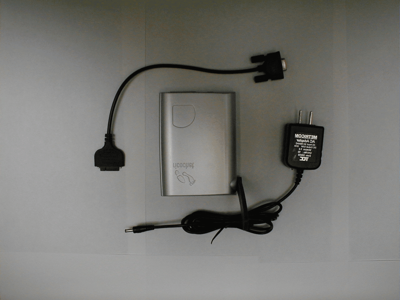
Jun 28, 2000Ricochet GT modem
Equipment Class
DSS - Part 15 Spread Spectrum Transmitter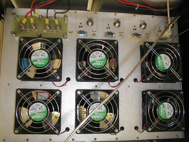
GNW70000
May 17, 2000Metricom WCS WAP
Equipment Class
TNB - Licensed Non-Broadcast Station Transmitter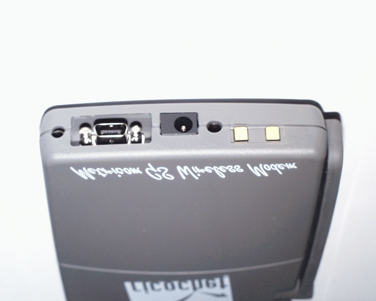
GNW21100
Mar 05, 2000Ricochet GS wireless Modem
Equipment Class
DSS - Part 15 Spread Spectrum TransmitterGNW21071
Oct 01, 1997Industrial Communications Radio Maximum output power: 1 W This device must be professionally installed.
Equipment Class
DSS - Part 15 Spread Spectrum TransmitterGNW21022
Dec 16, 1996Data Radio Module Maximum output power: 1 Watt
Equipment Class
DSS - Part 15 Spread Spectrum Transmitter