GNW22131Ricochet GT modem
Ricochet Networks, Inc.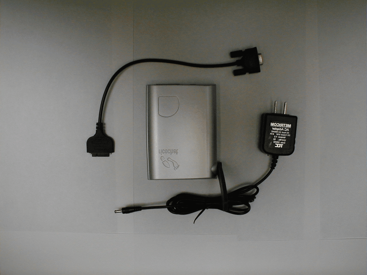
Click to zoom
Application Details
- Equipment Class
- DSS - Part 15 Spread Spectrum Transmitter
- Date of Grant
- Jun 28, 2000
- Application Purpose
- Original Equipment
- Date of Application
- May 14, 2000
- Equipment Note
- Ricochet GT modem
- Frequency Range
- 902.24000000 - 927.84000000
- Company
- Ricochet Networks, Inc.
- Country
- United States
Documents & Files
Document Text
Text extracted from the exhibit documents filed with the FCC. Open a document above to read the original.
Users Manual
To you computer Dual USB/Serial port on your modem 3 6 Hardware Installation(You will find that the battery is already plugged into the modem.)1 Plug the modem cable’s connector into the modem.2 Plug the other end of the cable into an available USB port in the computer. Note: USB port locations may differ on your particular computer. Installing your Ricochet Software/DriversWindows 98 should detect the device and ask for a device driver.Direct the installer to your Win98\metusb folder on this CD. Win-dows may ask for the Windows98 CD to be inserted or located forcertain Windows-supplied drivers. Point the installer to Win98 for allrelated requests.Follow the on-screen instructions.Add a dialup networking entry in the usual way, using the newlyinstalled USB modem.NOTE: Some PCs have issues and exhibit conflict between infrared /virtual devices and the USB modem. Try disabling the virtual driversin control panel → system → Device manager → Ports (com & lpt). To wall socketPower jack on your modem 4 5 Registering on the Ricochet Network1 Turn on the modem. You can switch to “silent” mode or “tone” mode. 2 Listen for a single beep, and wait for the modem’s red light to turn on, indicating that the modem has powered on. 3 Wait for the modem’s green light to blink, indicating that your modem has registered on the network. You will hear a two-tonebeep. Of course, if your modem is operating in silent mode, you will nothear the tones. “Tone”“ Silent Mode ” “ Off ” ^ Red Light: power _ Green light , blinking: registered on Ricochet Network Charging the battery1 You can charge the battery while the modem is in use.2 To charge the battery, connect the AC adapter to the modem.3 Plug the adapter into any household power outlet.The battery will continue to charge, even if you are using themodem. When the modem is not in use, the average charge time is2 hours. During use, the full charge time is longer. 7 2 Starting Your Ricochet Session(Your modem should already be on and blinking green.)1 You will be prompted to connect to the Ricochet wireless “777” Internet access. Click Connect . and Ending Your Ricochet Session...2 In the [Connected to Ricochet] window, select Disconnect. When the connection ends, you will hear a descending sequence of tones. FCC Compliance - DRAFTThis device complies with Part 15 of the FCC Rules. Operation is subjectto the following two conditions: (1) this device may not cause harmful inter-ference, and (2) this device must accept any interference received, includinginterference that may cause unwanted operation.This equipment complies with the limits for a Class B digitaldevice, pursuant to Part 15 of the FCC Rules. These limits are designed to pro-vide reasonable protection against radio frequency energy and, if not installedand used in acco rdance with the instructions, may cause ha r mful inte r ference to radio communications. However, there is no guarantee that interference willnot occur in a particular installation. If this equipment does cause ha rmful interference to radio or television reception, which can be determined by turn-ing the equipment off and on, the user is encouraged to try to correct the inter-ference by one or more of the following safety measures:• Reorient or relocate the receiving antenna.• Increase the separation between the equipment and receiver.• Consult the dealer or an experienced radio modem technician for help.This device is required to comply with FCC RF exposure requirements for mobiletransmitting devices. A separation distance of 12cm (5 inches) or mo re must be maintained between the antenna and all persons during device operations tosatisfy RF exposu re compliance. FCC ID: GNW22131 Patents:4,939,726, 5,903,566, 5,115,433, 5,130,987, 5,400,338, 5,453,977, 5,471,469,5,479,400, 5,488,608, 5,515,369, 5,570,084, 5,664,194 8 QuickStart Welcome to Ricochet! You are about to experience truefreedom for the first time. Ricochet sets you free fromthe office with mobile access to e-mail, the Internet andcompany networks from anywhere in our coverageareas—without being tied to a wall jack. This meansyou can work when, where, and how you want to withthe information you need just a few clicks away.Imagine responding to email from the back of a taxi ordownloading a presentation sitting in a client’s conferenceroom. Or staying online while waiting at thedoctor’s office. Or doing business from acoffee shop. You get the picture.We think you’ll agree that Ricochetchanges everything. ^_ _ Yellow light, blinking: Connected to Internet Getting on the Internet1 Make sure the modem is on and registered on the Ricochet network (blinking green light). 2 Double-click the [Dial Ricochet] icon. 3 Click the Connect button. The yellow light will blink and you will hear several two-tonebeeps (if your modem is not in silent mode). 4 Start your web browser.
Users Manual
Company Classified Attaching your Ricochet Modem to a Laptop Computer Your Ricochet modem can be attached to your laptop computer for convenience. The modem accesory kit includes adhesive-backed Velcro strips for this purpose. Use these instructions to attach your modem to your laptop correctly. 1. Remove the plastic backing from the hook side Velcro strips to expose the adhesive. 2. Affix these strips to rear of the modem, taking care not to obstruct any openings or labels. Press the strips to the modem firmly to ensure contact. 3. Attach the loop side Velcro strips to the hook strips. Remove the plastic backing from the loop side Velcro to expose the adhesive. 4. Align the top edge of the modem with the top edge of the com- puter screen for unrestriced antenna travel. Press the modem and exposed adhesive strips onto the back of your laptop com- puter screen. 5. Go to the Hardware Installation section of your QuickStart guide for further installation instructions. The modem can be removed and re-attched easily, using the velcro strips. Your modem can be used without attaching it to your computer: 1. Place the modem alongside the computer. 2. Make sure the antenna has an unrestricted range of movement. 3. Go to the Hardware Installation section of your QuickStart guide for further installation instructions. Laptop computer with a Ricochet modem attached. Laptop computer with a Ricochet modem unattached.
RF Exposure Info
MPE Assessment for the GT Wireless Modem, GNW 22131 GT_mpe_calc.doc GS Wireless Modem MPE Calculations 05/15/00 Metricom, Inc. 980 University Avenue Los Gatos, CA, 93030 (Tel) 408-399-8200 (Fax) 408-354-1024 Federal Communications Commission Maximum Permissible Exposure Assessment for the Metricom GT modem, GNW 22131 In accordance with FCC REPORT AND ORDER 96-326 Adopted: August 1, 1996 MPE Assessment for the GT Wireless Modem, GNW 22131 GT_mpe_calc.doc GS Wireless Modem MPE Calculations 05/15/00 Background: The Metricom GS wireless modem is a frequency hopping spread spectrum radio-modem that operates within the 902-928 MHz band. The peak transmit output power of the radio is 1 Watt. The modem is capable of communicating with either Micro-Cellular Data Network (MCDN) microcell radios (GNW 21000) that make up the MCDN network or other MCDN compatible wireless modems. The modem uses a 1 dBi gain omni-directional monopole antenna. Testing has determined that the typical Tx duty cycle for a modem communicating over the MCDN network is less than 5%. Even though the 5% level is at the upper limit of typical operation, a duty cycle of 100% is used here to yield a worst case analysis. The modem is a classified as a mobile device and is intended to be mounted to the back of a laptop computer display or sit on the desk next to the laptop computer. MPE Calculations. The environment in which the modem operates is “uncontrolled”. The definitions of controlled and uncontrolled environments are included below from the FCC Report and Order 96-326:B. Definitions of Controlled and Uncontrolled Environments 35. The 1992 ANSI/IEEE guidelines specify two sets of exposure limits based on the "environment" in which the exposure takes place. These environments are classified as either "controlled" or "uncontrolled." Controlled environments are defined as locations where "there is exposure that may be incurred by persons who are aware of the potential for exposure as a concomitant of employment, by other cognizant persons, or as the incidental result of transient passage through areas where analysis shows the exposure levels may be above [the exposure and induced current levels permitted for uncontrolled environment but not those permitted for controlled environments]." Uncontrolled environments are defined as "locations where there is the exposure of individuals who have no knowledge or control of their exposure. The exposures may occur in living quarters or workplaces where there are no expectations that the exposure levels may exceed [the exposure and induced current levels permitted for uncontrolled environments]." MPE Assessment for the GT Wireless Modem, GNW 22131 GT_mpe_calc.doc GS Wireless Modem MPE Calculations 05/15/00 Uncontrolled Environment Spec: f(MHz)/1500 mW/cm^2 902/1500 = .6 mW/cm^2 In this case the modem may be mounted behind the monitor of a laptop or sitting on the desk next to the laptop that it is connected to. If the modem is on the desk next to the laptop, then the minimum distance between the users hand would typically be 5 inches. If the unit were mounted on the back of a laptop display, the typical minimum distance would be approximately 12 to 15 inches. Calculation: MPE Dist(cm)= SQRT( (Ant Gain(Ratio)*Pout(mw)*Duty Cycle)/(Limit(mw/cm^2) *4 * PI) ) = SQRT( ( 1.25 * 1000 * 1 / .6 *4 * PI) ) = SQRT( ( 1046.25 / 7.534 ) ) = SQRT (165.870) MPE Dist(cm) = 12.87 cm MPE Dist(in) = 5.07 in Conclusion: The typical distance between the user of the modem is approximately 3 to 4 times greater than the MPE distance under typical use. Since the modem is a mobile device, and the MPE distance is below the minimum separation distance required of a mobile device, a statement will appear in the modem user manual that will require users to maintain a minimum 20 cm distance between the modem antenna and all persons, during modem operation. MPE Distance (cm) Antenna Gain (as a ratio) * Pout(mw) * Duty Cycle Exposure Limit ( mw/cm^2) * 4 * Π MPE Assessment for the GT Wireless Modem, GNW 22131 GT_mpe_calc.doc GS Wireless Modem MPE Calculations 05/15/00 Exposure Limits from FCC96-326 Report and Order, Appendix C, Final Rules is given below. Table 1. Limits for Maximum Permissible Exposure (MPE) (B) Limits for General Population/Uncontrolled Exposure ______________________________________________________________________________ Frequency Electric FieldMagnetic Field Range Strength Strength Power Density Averaging Time (MHz) (V/m) (A/m) (mW/cm2) (minutes) ______________________________________________________________________________ 0.3-1.34 614 1.63 (100)* 30 1.34-30 824/f 2.19/f (180/f2)* 30 30-300 27.5 0.073 0.2 30 300-1500 -- -- f/1500 30 1500-100,000 -- -- 1.0 30 ______________________________________________________________________________ f = frequency in MHz * = Plane-wave equivalent power density NOTE 1 TO TABLE 1: Occupational/controlled limits apply in situations in which persons are exposed as a consequence of their employment provided those persons are fully aware of the potential for exposure and can exercise control over their exposure. Limits for occupational/controlled exposure also apply in situations when an individual is transient through a location where occupational/controlled limits apply provided he or she is made aware of the potential for exposure. NOTE 2 TO TABLE 1: General population/uncontrolled exposures apply in situations in which the general public may be exposed, or in which persons that are exposed as a consequence of their employment may not be fully aware of the potential for exposure or can not exercise control over their exposure.
RF Exposure Info
To you computer Dual USB/Serial port on your modem 36 Hardware Installation (You will find that the battery is already plugged into the modem.) 1 Plug the modem cable’s connector into the modem. 2 Plug the other end of the cable into an available USB port in the computer. Note: USB port locations may differ on your particular computer. Installing your Ricochet Software/Drivers Windows 98 should detect the device and ask for a device driver. Direct the installer to your Win98\metusb folder on this CD. Win- dows may ask for the Windows98 CD to be inserted or located for certain Windows-supplied drivers. Point the installer to Win98 for all related requests. Follow the on-screen instructions. Add a dialup networking entry in the usual way, using the newly installed USB modem. NOTE: Some PCs have issues and exhibit conflict between infrared / virtual devices and the USB modem. Try disabling the virtual drivers in control panel→system→Device manager→Ports (com & lpt). To wall socket Power jack on your modem 45 Registering on the Ricochet Network 1 Turn on the modem. You can switch to “silent” mode or “tone” mode. 2 Listen for a single beep, and wait for the modem’s red light to turn on, indicating that the modem has powered on. 3 Wait for the modem’s green light to blink, indicating that your modem has registered on the network. You will hear a two-tone beep. Of course, if your modem is operating in silent mode, you will not hear the tones. “Tone” “Silent Mode” “Off” ^ Red Light: power _ Green light , blinking: registered on Ricochet Network Charging the battery 1 You can charge the battery while the modem is in use. 2 To charge the battery, connect the AC adapter to the modem. 3 Plug the adapter into any household power outlet. The battery will continue to charge, even if you are using the modem. When the modem is not in use, the average charge time is 2 hours. During use, the full charge time is longer. 72 Starting Your Ricochet Session (Your modem should already be on and blinking green.) 1 You will be prompted to connect to the Ricochet wireless “777” Internet access. Click Connect. and Ending Your Ricochet Session... 2 In the [Connected to Ricochet] window, select Disconnect. When the connection ends, you will hear a descending sequence of tones. FCC Compliance This device complies with Part 15 of the FCC Rules. Operation is subject to the following two conditions: (1) this device may not cause harmful inter- ference, and (2) this device must accept any interference received, including interference that may cause unwanted operation. This equipment complies with the limits for a Class B digital device, pursuant to Part 15 of the FCC Rules. These limits are designed to pro- vide reasonable protection against radio frequency energy and, if not installed and used in accordance with the instructions, may cause harmful interference to radio communications. However, there is no guarantee that interference will not occur in a particular installation. If this equipment does cause harmful interference to radio or television reception, which can be determined by turn- ing the equipment off and on, the user is encouraged to try to correct the inter- ference by one or more of the following safety measures: • Reorient or relocate the receiving antenna. • Increase the separation between the equipment and receiver. • Consult the dealer or an experienced radio modem technician for help. This device is required to comply with FCC RF exposure requirements for mobile transmitting devices. A separation distance of 20cm (8 inches) or more must be maintained between the antenna and all persons during device operations to satisfy RF exposure compliance. FCC ID: GNW22131 Patents: 4,939,726, 5,903,566, 5,115,433, 5,130,987, 5,400,338, 5,453,977, 5,471,469, 5,479,400, 5,488,608, 5,515,369, 5,570,084, 5,664,194 8 QuickStart Welcome to Ricochet! You are about to experience true freedom for the first time. Ricochet sets you free from the office with mobile access to e-mail, the Internet and company networks from anywhere in our coverage areas—without being tied to a wall jack. This means you can work when, where, and how you want to with the information you need just a few clicks away. Imagine responding to email from the back of a taxi or downloading a presentation sitting in a client’s conference room. Or staying online while waiting at the doctor’s office. Or doing business from a coffee shop. You get the picture. We think you’ll agree that Ricochet changes everything. ^_ _ Yellow light, blinking: Connected to Internet Getting on the Internet 1 Make sure the modem is on and registered on the Ricochet network (blinking green light). 2 Double-click the [Dial Ricochet] icon. 3 Click the Connect button. The yellow light will blink and you will hear several two-tone beeps (if your modem is not in silent mode). 4 Start your web browser.
RF Exposure Info
To: david waitt, Metricom, Inc From: Errol Chang [email protected] FCC Application Processing Branch Re: FCC ID GNW22131 Applicant: Metricom Incorporated Correspondence Reference Number: 14153 731 Confirmation Number: EA97597 Date of Original E-Mail: 05/19/2000 1. In the MPE report the gain of the antenna is listed as 1 dBi, while in the test report it is listed as 0 dBi. Please clarify. METRICOM: The typical gain is 0 dBi, the max gain at some points in the pattern may be as high as 1 dBi. Since 0 dBi is the typical; specified gain, it is called out in the report, but since 1dBi is the worst-case gain, I used that in the MPE calculation. The sketch at right shows a possible antenna pattern (of course the pattern varies slightly form antenna to antenna). The typical gain is 0 dBi but there are some peaks out to 1 dBi. 2. Please revise the RF Exposure statement in the manual so that the allowable usage configurations are specifically stated . I note that the MPE report lists mounting on the back of a laptop pc as a possible configuration, but this is not addressed in the manual, nor is any other allowable configuration. METRICOM: The manual that was included in the certification application is preliminary and usage configurations had not been included at that time. Metricom has since generated draft pages for the customer usage configurations. Pages similar to the ones included here will appear in the manual. 3. In addition, the actual distance listed in the current manual statement is 12 cm, and not 20 cm. Please correct. Also, please indicate, in the statement, why a minimum separation distance of 20 cm is required (e.g., in order to be classified as a mobile, instead of portable, device). We ask this because we do not have SAR data for the EUT, whereas, for instance, a Part 22 CDPD modem is required to submit SAR data for potential portable configurations. METRICOM: The typical distance between the user and the EUT antenna when the EUT used in the configurations specified in the manual is more than 20cm. Therefore, the statement in the manual has been edited to specify a minimum MPE distance of 20 cm, and thus we will classify the device as a mobile device. The edited, final version of the FCC statement and the preliminary pages showing customer configurations is included. Please revise accordingly, and make the statement more readily apparent in the manual. Please submit the FINAL version of the statement, as opposed to a draft. The items indicated above must be submitted before processing can continue on the above referenced application. Failure to provide the requested information within 60 days of the original e-mail date may result in application dismissal pursuant to Section 2.917 (c) and forfeiture of the filing fee pursuant to section 1.1108. 1 dBi 0 dBi Possible Pattern DO NOT reply to this e-mail by using the Reply button. In order for your response to be processed expeditiously, you must upload your response via the Internet at www.fcc.gov, Electronic Filing, OET Equipment Authorization Electronic Filing. If the response is submitted through Add Attachments, in order to expedite processing, a message which informs the processing staff that a new exhibit has been submitted must also be submitted via Submit Correspondence. Also, please note that partial responses increase processing time and should not be submitted. Any questions about the content of this correspondence should be directed to the e- mail address listed below the name of the sender.
RF Exposure Info
1 Quick Start Welcome to Ricochet! You are about to experience true freedom for the first time. Ricochet sets you free from the office with mobile access to e- mail, the Internet and company networks from anywhere in our coverage areas—without being tied to a phone jack. This means you can work when, where, and how you want to with the information you need, just a few clicks away. Imagine responding to e-mail from the back of a taxi, or downloading a presentation while sitting in a client’s conference room. Or stay- ing online while waiting at the doctor’s office. Or doing business from a coffee shop. You get the picture. We think you’ll agree that Ricochet changes everything. 2 This device complies with Part 15 of the FCC Rules. Operation is subject to the fol- lowing two conditions: (1) this device may not cause harmful interference, and (2) this device must accept any interference received, including interference that may cause unwanted operation. This equipment complies with the limits for a Class B digital device, pursuant to Part 15 of the FCC Rules. These limits are designed to provide reasonable protection against radio frequency energy and, if not installed and used in accordance with the instructions, may cause harmful interference to radio communications. However, there is no guarantee that interference will not occur in a particular installation. If this equipment does cause harmful interference to radio or television reception, which can be determined by turning the equipment off and on, the user is encouraged to try to correct the interference by one or more of the following safety measures: • Reorient or relocate the receiving antenna. • Increase the separation between the equipment and receiver. • Consult the dealer or an experienced radio modem technician for help. Caution: This device is required to comply with FCC RF exposure requirements for mobile transmitting devices. A separation distance of 20cm (8 inches) or more must be maintained between the antenna and all persons during device opera- tions to satisfy RF exposure compliance. FCC ID: GNW22131 Device covered by the following patents: 4,939,726; 5,903,566; 5,115,433; 5,130,987; 5,400,338; 5,453,977; 5,471,469; 5,479,400; 5,488,608; 5,515,369; 5,570,084; 5,664,194 FCC Compliance 3 Exit other programs before starting the Ricochet installer. Make sure your Ricochet modem is not connected to your computer before you begin the software installation. 1.Insert the Ricochet installation CD into your computer. 2.Double-click the My Computer icon. 3.Locate the icon for your CD-ROM. Right-click this icon and select Open. 4.Double-click the R2 Setup icon to begin the installation process. Fig. 1: The Ricochet Installer Welcome screen 5.Click Next to review the Ricochet software license agreement. Installing the Ricochet Software 4 •Read the license agreement. If you agree to the terms, click the Ye s but- ton. •Click No to refuse the terms of the agreement. R2Setup will exit, and no installation will take place. 6.Connect the modem to your PC. Turn the modem on. •Plug the modem cable’s connector into the modem. •Plug the free end of the cable into an available USB or serial port in the computer. Fig. 2: Ricochet modem and USB cable Installing the Ricochet Software 5 7.Turn on your Ricochet modem. Fig. 3: Power switch detail Fig. 4: Modem setup cable type •Select Ricochet Wireless USB modem to use a USB cable. •Select Ricochet Wireless Serial modem to use a serial cable. 8.Click Next to install the Ricochet connection software. Installation should take one to two minutes. 9.To use your Ricochet modem, you must restart your computer. Installing the Ricochet Software 6 Fig. 5: Final Setup screen On the final setup screen: •Select Ye s to restart your computer now. •Select No to restart your computer later. Click Finish to complete the installation. Installing the Ricochet Software 7 To fully charge your Ricochet modem battery: 1.Connect the AC adapter to the modem. 2.Plug the adapter into a 110v household power outlet. Fig. 6: Your Ricochet modem and power adapter •The modem battery will charge during use. •When the modem is switched off, the required charging time is about two hours. During use, charging time will be longer. Charging your Modem Battery 8 When your modem is turned on, it automatically seeks out the Ricochet net- work . Once the network is found, the modem signals with tones and a green light. To register on the network: 1.Extend the antenna on your modem. 2.Turn on the modem. Place the switch in Power On with tone position. You can also use Power on without tone mode. 3.Listen for a single beep, and wait for the modem’s red light to turn on, indicating that the modem is receiving power. 4.Wait a moment for the modem’s green light to blink, indicating that your modem has registered on the network. Fig. 7: Power switch detail Fig. 8: Tone key Registering on the Ricochet Network 9 1.Connect your modem, turn it on, and verify that it is registered on the Ricochet network. (See page 8) 2.Locate the Connect to Ricochet icon in your Dial-up networking folder. Double-click the icon. 3.Enter your name and Ricochet password in the Connect To dialog box. 4.Click the Connect button in the Connect To dialog box. Fig. 9: Connect To dialog box You will hear a short series of ascending tones, and the blinking green light on your modem will change to orange as your modem connects to the Inter- net. Once the modem is connected, you’ll be able to use your Internet applica- tions, like web browsers and e-mail, via the Ricochet wireless network. •To end your Ricochet session, click the Disconnect button in the Con- nect To dialog box, wait for the descending tones, and turn your modem off. Connecting to the Internet Metricom, Inc. P/N 109266-000 Rev.A
Test Report
Metricom, Inc. 980 University Avenue Los Gatos, CA, 93032 (Tel) 408-399-8200 (Fax) 408-354-1024 Part 15 Certification Application for FCC ID: GNW 22131 EMI Test Report and Technical Documentation on “GT” Wireless Modem for use on the Metricom MCDN Network Prepared by: Metricom, Inc 980 University Ave. Los Gatos, CA 95032 Test date(s): April / May 2000 Schematics, block diagrams and algorithm descriptions subject to enclosed confidentiality statement Metricom, Inc. GNW 22131 FCC Part 15 Certification Application May 2000 Gt_summary_report.doc (dw8) Page #:2 1.0 Verification of Compliance Description: Ricochet GT Wireless Modem Model Number: 22131 Serial Number(s): Pre-Production Models Applicant: Metricom Inc. Type of Test: FCC part 15.247 Application for Part 15 Certification under GNW 22131 Date(s) of test: April / May 2000 Tested By David Waitt (Metricom, Los Gatos, CA) Chris Byleckie (Elliott Labs, Sunnyvale,CA) The above equipment was tested by Metricom Inc. and Elliott Labs and found to be in compliance with the requirements set forth in Part 15 of the FCC Rules and Regulations. David Waitt Engineer Metricom, Inc. Metricom, Inc. GNW 22131 FCC Part 15 Certification Application May 2000 Gt_summary_report.doc (dw8) Page #:3 2.0 General Information Applicant: Metricom, Inc 980 University Ave Los Gatos, CA 95032 Contact Person David Waitt Equipment Under Test: Ricochet GT Wireless Modem Model Number: 22131 Serial Number(s): Pre-Production models Manufacturer: Metricom, Inc Type of Test: FCC Part 15.247 Certification, FCC ID GNW-22131 Reason for testing: Metricom Inc. has developed a new version of the Ricochet Wireless modem for use with the new high speed Ricochet wireless micro-cellular data network (MCDN). It is similar in general functionality to the current Ricochet Wireless modem (FCC ID: GNW 21100). The modem will be sold or rented to subscribers of Metricom’s Ricochet service. The Ricochet service allows subscribers to send / receive email, connect to the Internet, etc. without the necessity of a telephone line. The Ricochet GT modem (Model 22131) is a frequency hopping spread spectrum radio- modem that operates within the 902-928 MHz band. The modem transmits and receives digital packet data. The transmit power of the modem is just below 1 Watt. The modems are capable of communicating with MCDN radios that make up the MCDN network or other modems. A technical overview of the MCDN network is contained in the Appendix. The new GT Ricochet modem is capable for four different modulations. “GEN1” - To communicate with the older, first generation network (It is 2FSK w/ special info in the header of the packet) “2FSK” - 2 “position” frequency shift keying “4FSK” - 4 “position” frequency shift keying “pi/4 DPSK - 4 “position” phase shift keying These are referred to as MOD 0, 1, 2 and 3 respectively. The modulations are chosen automatically by the modem depending on the robustness of the communications link between itself and the Network Radio (GNW 24000) Metricom, Inc. GNW 22131 FCC Part 15 Certification Application May 2000 Gt_summary_report.doc (dw8) Page #:4 3.0 Results Summary Summary: Since this is a new certification request, a complete set of tests demonstrating compliance with FCC Part 15.247 was conducted. Compliance with the following Part 15 regulations was verified: Paragraph Test Results 15.247(b) Maximum Power Output at Antenna Terminals + 29.90 dBm Max 15.247(a)(1)(i) Minimum Number of Hopping Channels 50 Demonstrated 50 (Actual) 15.247(a)(1) Channel Frequency Separation 160 kHz (by design) 15.247(a)(1) Average Channel Occupancy Time 43.5 ms / 20 Sec Avg. 15.247(c) Out of Band Conducted Emissions - 27.8 dB @ band edge Out of Band Conducted Emissions (1 – 10 GHz) –69 dBc @ 931.84MHz . 15.205 (a) Radiated Emissions in Restricted bands .3 dB i…
Text truncated - open the document above for the full version.
Contact Information
Applicant
Kathy Eberhart(Paralegal)
Technical Contact
Metricom, Incdavid waitt
[email protected]408 399 8126
980 university ave · los gotos, California · United States
Non-Technical Contact
Metricom, incdavid waitt
[email protected]408 399 8126
Technical Specifications
| # | Rule Parts | Frequency Range | Power Output |
|---|---|---|---|
| 1 | 15C | 902.24 MHz - 927.84 MHz | 977.00 mW |
Other Applications from Ricochet Networks, Inc.
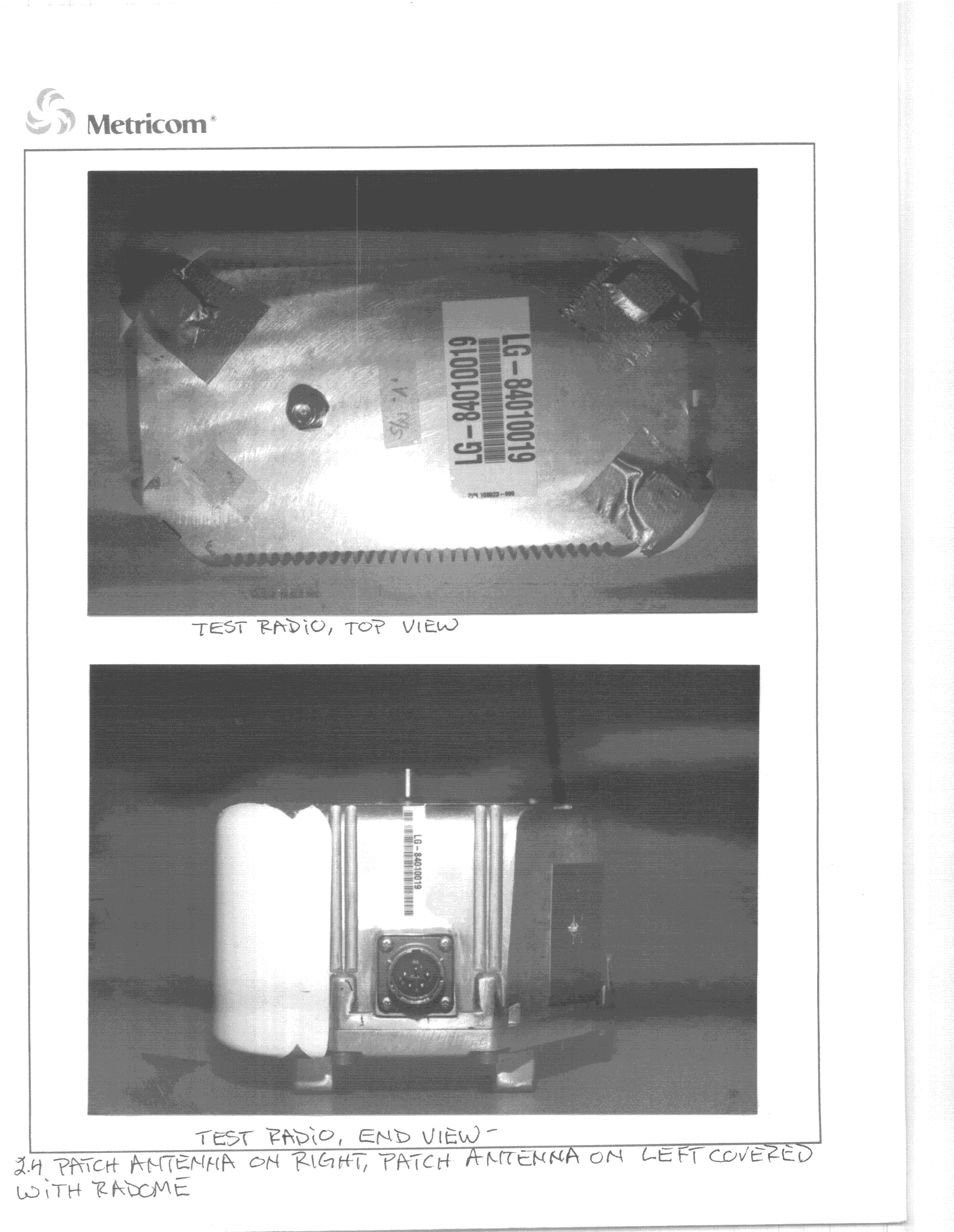
GNW24000
Jul 04, 2000DSS - Part 15 Spread Spectrum Transmitter
Equipment Class
DSS - Part 15 Spread Spectrum Transmitter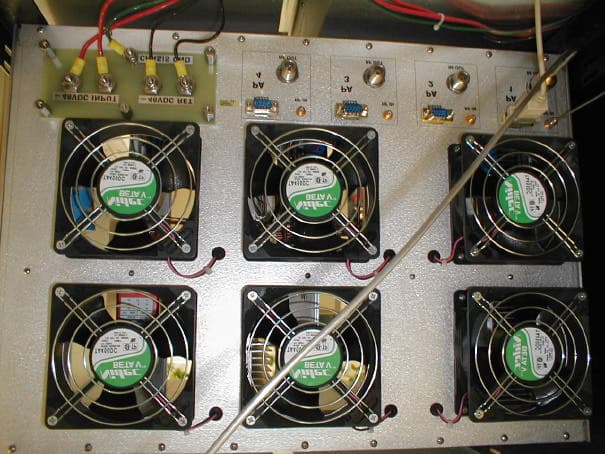
GNW70000
May 17, 2000Metricom WCS WAP
Equipment Class
TNB - Licensed Non-Broadcast Station Transmitter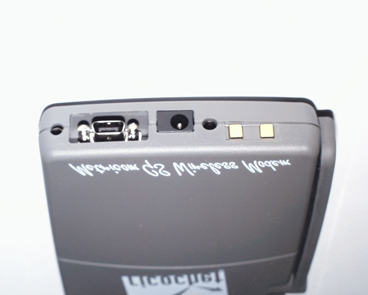
GNW21100
Mar 05, 2000Ricochet GS wireless Modem
Equipment Class
DSS - Part 15 Spread Spectrum TransmitterGNW21071
Oct 01, 1997Industrial Communications Radio Maximum output power: 1 W This device must be professionally installed.
Equipment Class
DSS - Part 15 Spread Spectrum TransmitterGNW21022
Dec 16, 1996Data Radio Module Maximum output power: 1 Watt
Equipment Class
DSS - Part 15 Spread Spectrum Transmitter