GTC-201705XL510 Lamp Controller
Honeywell International Inc.
Click to zoom
Application Details
- Equipment Class
- DTS - Digital Transmission System
- Date of Grant
- Mar 22, 2021
- Application Purpose
- Original Equipment
- Date of Application
- Mar 22, 2021
- Equipment Note
- L510 Lamp Controller
- Frequency Range
- 2405.00000000 - 2480.00000000
- Company
- Honeywell International Inc.
- Country
- United States
Documents & Files
Document Text
Text extracted from the exhibit documents filed with the FCC. Open a document above to read the original.
Users Manual
1 L510 Lamp Controller Overview The L510 Lamp Controller is designed for the hospitality industry to provide convenient switched and dimming control of several different load types, including; incandescent, CFL and LEDs. By doing this, it converts any standard lamp into a remotely controlled lamp with the ability to create scenic and mood lighting. The L510 is able to participate in Honeywell’s overall Energy Management System (EMS) to provide energy savings along with enhanced guest experience. A typical application would include a L510 controlling scenic lighting around a headboard of a guestroom bed. To provide this control, the L510 is equipped with an INNCOM WBI relay, Triac or FET actuator and communicates via the on-board 2.4Ghz radio over the INNCOM DeepMesh network. The L510 which is controlling the lamp can be controlled by an INNCOM MODEVA or EVORA switch as well as also be controlled locally. Other applications include; desk and floor lamp control as well as wall sconce control. . Part Numbers PART NUMBERS DESCRPTION 201-7050 Relay Actuator RF Lamp Controller, 120-240VAC, 500W 201-7051 Triac Dimmer RF Lamp Controller, 120VAC, 650W 201-7052 FET Dimmer RF Lamp Controller, 120VAC, 350W System Layout Figure 1 L510 Lamp Controller Load Ratings Model Rating Voltage Freq Power / Amperes Type of Load 201-7050 (Relay) 120-240 Vac 50/60 Hz 4.1 A Resistive 120-240 Vac 50/60 Hz 4.1 A General Purpose 120-240 Vac 50/60 Hz 500 W Tungsten / ELV 120-240 Vac 50/60 Hz 250 VA Electric Ballast 120-240 Vac 50/60 Hz 1/10 HP Motor 201-7051 (Triac) 120 Vac 60 Hz 2.9 A Resistive 120 Vac 60 Hz 2.9 A General Purpose 120 Vac 60 Hz 650W Tungsten / ELV 120 Vac 60 Hz 250 VA Electronic Ballast 120 Vac 60 Hz 1/10 HP Motor 201-7052 (FET) 120 Vac 60 Hz 2.9 A Resistive 120 Vac 60 Hz 2.9 A General Purpose 120 Vac 60 Hz 350 W Tungsten / ELV 120 Vac 60 Hz 250 VA Electronic Ballast Product Specification Parameter Specification Range / Value S5 Bus Data Rate 2550bps Range 50ft Max Nodes 20 DeepMesh RF Range 70ft Transmit Power +5dBm Receive Sensitivity -95dBm Protocol IEEE 802.15.4 Frequency Band 2405MHz – 2480MHz Channels 11-26 I/O Digital input / outputs 2 dry contact inputs / UART pins Power Input Voltage 120Vac Device Power Consumption 12VDC, 100mA Max DC Power 200mA (100mA available to power external device on 12Vdc) Environment Operating Temperature 0 -30C Storage Temperature -10 – 50C Humidity 10 – 90% RH, Non-condensing Approvals CFR47 FCC Part 15.247 Subpart C CR47 FCC Part 15 Subpart B RSS-247 Issue 2 ICES-003 Issue 6 RSS-Gen Issue 5 Rss-102 Issue 5 RJ-12 Low Voltage Connector RJ-9 Switch Connector Pin Typical Color* Function 1 White GND 2 Black +12V 3 Red S5 Bus 4 Green INPUT 1 / UART- Tx 5 Yellow INPUT 2 / UART - Rx 6 Blue NC *Wire colors may differ Conformance statement FCC ID: GTC-201705X This device complies with part 15 of the FCC Rules. Operation is subject to the following two conditions: (1) This device may not cause harmful interference, and (2) this device must accept any interference received, including interference that may cause undesired operation. CAUTION: changes or modifications not expressly approved by the party responsible for compliance could void the user's authority to operate the equipment. NOTE: This equipment has been tested and found to comply with the limits for a Class B digital device, pursuant to part 15 of the FCC Rules. These limits are designed to provide reasonable protection against harmful interference in a residential installation. This equipment generates, uses and can radiate radio frequency energy and, if not installed and used in accordance with the instructions, may cause harmful interference to radio communications. However, there is no guarantee that interference will not occur in a particular installation. If this equipment does cause harmful interference to radio or television reception, which can be determined by turning the equipment off and on, the user is encouraged to try to correct the interference by one or more of the following measures: Reorient or relocate the receiving antenna. Increase the separation between the equipment and receiver. Connect the equipment into an outlet on a circuit different from that to which the receiver is connected. Consult the dealer or an experienced radio/TV technician for help. Any changes or modifications not expressly approved by the party responsible for compliance could void the user's authority to operate this equipment. IC: 1609A-201705X This device contains licence-exempt transmitter(s)/receiver(s) that comply with Innovation, Science and Economic Development Canada’s licence-exempt RSS(s). Operation is subject to the following two conditions: 1. This device may not cause interference. 2. This device must accept any interference, including interference that may cause undesired operation of the device. L’émetteur/récepteur exempt de licence contenu dans le présent appareil est conforme aux CNR d’Innovation, Sciences et Développement économique Canada applicables aux appareils radio exempts de licence. L’exploitation est autorisée aux deux conditions suivantes : 1. L’appareil ne doit pas produire de brouillage; 2. L’appareil doit accepter tout brouillage radioélectrique subi, même si le brouillage est susceptible d’en compromettre le fonctionnement. Wiring CAUTION Only a trained, experienced service technician should install the L510. Before beginning, the installer should check the ratings given in the instructions and on the product to make sure the product is suitable for the application. The installer must disconnect the AC from the drape motor power supply before beginning the installation to prevent electrical shock or equipment damage. All wiring must comply with local codes and ordinances. The L510 is intended for INDOOR USE ONLY. It is important to read the instructions carefully. Failure to follow them could damage the product or cause a hazardous condition. Ordering Specifications Model …
Text truncated - open the document above for the full version.
Cover Letter(s)
Honeywell Internal January 29, 2021 Attention: Application Examiner RE: Request for Confidentiality Applicant: Honeywell International Inc. FCC ID: GTC-201705X To Whom It May Concern: Permanent Confidentiality Request is hereby submitted by Honeywell International Inc. to withhold permanently from public review certain portions of the application for equipment certification for the referenced FCC identifiers. This request for confidentiality is made pursuant to 47 CFR 0.457(d) and 0.459 of the FCC Rules. In particular, the following sections of the application are to be kept permanently confidential: • Schematics • Detailed Block Diagrams • Detailed Operational/Functional Description Short-term Confidentiality Request is hereby submitted by Honeywell International Inc. to withhold from public review for a period of 180 days from the date of the Grant of Equipment Authorization and prior to marketing, certain portions of the application for equipment certification for the referenced FCC identifiers. This request for confidentiality is made pursuant to 47 CFR 0.457(d) and 0.459 of the FCC Rules. In particular, the following sections of the application are to be kept confidential for a period of 180 days from the date of Authorization: • Test setup photos • External photos (NOTE: External photos can only be held for short-term confidentiality) • Internal photos Honeywell Internal Rationale for request for confidentiality: Honeywell International Inc. has invested considerable time and materials in research and development to produce the referenced product. Permanent confidentiality: Disclosure of the permanently confidential portions of this application to competitors would not only give them significant competitive advantages in developing similar products, but would also disclose successful implementation of unpublished, leading edge technology developed by us. Short term confidentiality: Disclosure of the short-term confidential portions of this application during the period of importation and/or distribution would reveal key aspects of proprietary technology to competitors and diminish the value of our investment in research and development. If you have questions or need further information, please contact the undersigned. Sincerely, Jeanne Enaux Sr. Engineering Manager Honeywell International Inc.
Test Report
Honeywell International, Inc. TEST REPORT SCOPE OF WORK EMISSIONS TESTING – L510 Lamp Controllers REPORT NUMBER 104161294BOX-001 ISSUE DATE [REVISED DATE] January 16, 2020 March 17, 2021 PAGES 92 DOCUMENT CONTROL NUMBER Non-Specific Radio Report Shell Rev. December 2017 © 2017 INTERTEK Non-Specific Radio Report Shell Rev. December 2017 Page 2 of 92 Client: Honeywell International, Inc. / L510 Lamp Controllers EMISSIONS TEST REPORT (FULL COMPLIANCE) Report Number: 104161294BOX-001 Project Number: G104161294 Report Issue Date: 01/16/2020 Report Revision Date: 03/17/2021 Model(s) Tested: Triac Model Number: 201-7051 Model(s) Partially Tested: Relay Model Number: 201-7050 FET Model Number: 201-7052 Model(s) Not Tested but declared equivalent by the client: None Standards: CFR47 FCC Part 15.247 Subpart C: 12/2019, CFR47 FCC Part 15 Subpart B: 12/2019, RSS-247 Issue 2 February 2017, ICES-003 Issue 6 Published: January 2016 Updated: April 2019, RSS-Gen Issue 5 April 2018, RSS-102 Issue 5 March 2015 Tested by: Client: Intertek Testing Services NA, Inc. 70 Codman Hill Road Boxborough, MA 01719 USA Honeywell International, Inc. 12 Clintonville Rd Northford, CT 06472 USA Report prepared by Report reviewed by Kouma Sinn / EMC Staff Engineer Vathana Ven / EMC Staff Engineer This report is for the exclusive use of Intertek's Client and is provided pursuant to the agreement between Intertek and its Client. Intertek's responsibility and liability are limited to the terms and conditions of the agreement. Intertek assumes no liability to any party, other than to the Client in accordance with the agreement, for any loss, expense or damage occasioned by the use of this report. Only the Client is authorized to permit copying or distribution of this report and then only in its entirety. Any use of the Intertek name or one of its marks for the sale or advertisement of the tested material, product or service must first be approved in writing by Intertek. The observations and test results in this report are relevant only to the sample tested. This report by itself does not imply that the material, product, or service is or has ever been under an Intertek certification program. Intertek Report Number: 104161294BOX-001 Issued: 01/16/2020 Revised: 03/17/2021 Non-Specific Radio Report Shell Rev. December 2017 Page 3 of 92 Client: Honeywell International, Inc. / L510 Lamp Controllers Table of Contents 1 Introduction and Conclusion .............................................................................................................. 4 2 Test Summary ...................................................................................................................................... 4 3 Client Information ................................................................................................................................ 5 4 Description of Equipment Under Test and Variant Models ............................................................. 5 5 System Setup and Method .................................................................................................................. 7 6 Maximum Peak Output Power and Human RF exposure ................................................................. 8 7 6 dB Bandwidth and Occupied Bandwidth ..................................................................................... 17 8 Maximum Power Spectral Density ................................................................................................... 23 9 Band Edge Compliance ..................................................................................................................... 27 10 Transmitter spurious emissions ................................................................................................... 36 11 Digital Device and Receiver Radiated Spurious Emissions ...................................................... 74 12 AC Mains Conducted Emissions .................................................................................................. 82 13 Revision History ............................................................................................................................. 92 Intertek Report Number: 104161294BOX-001 Issued: 01/16/2020 Revised: 03/17/2021 Non-Specific Radio Report Shell Rev. December 2017 Page 4 of 92 Client: Honeywell International, Inc. / L510 Lamp Controllers 1 Introduction and Conclusion The tests indicated in section 2.0 were performed on the product constructed as described in section 4.0. The remaining test sections are the verbatim text from the actual data sheets used during the investigation. These test sections include the test name, the specified test Method, a list of the actual Test Equipment Used, documentation Photos, Results and raw Data. No additions, deviations, or exclusions have been made from the standard(s) unless specifically noted. Based on the results of our investigation, we have concluded the product tested was found to Comply with the requirements of the standard(s) indicated. The results obtained in this test report pertain only to the item(s) tested. Intertek does not make any claims of compliance for samples or variants which were not tested. 2 Test Summary Section Test full name Result 3 Client Information -- 4 Description of Equipment Under Test and Variant Models -- 5 System Setup and Method -- 6 Maximum Peak Output Power and Human RF exposure CFR47 FCC Part 15 Subpart C:12/2019, Section 15.247 (b)(3) RSS-247 Issue 2 February 2017, RSS-102 Issue 5 March 2015 Pass 7 6 dB Bandwidth and Occupied Bandwidth CFR47 FCC Part 15 Subpart C: 12/2019, Section 15.247 (a)(2) RSS-247 Issue 2 February 2017 Pass 8 Maximum Power Spectral Density CFR47 FCC Part 15 Subpart C: 12/2019, Section 15.247 (e) RSS-247 Issue 2 February 2017 Pass 9 Band Edge Compliance CFR47 FCC Part 15 Subpart C: 12/2019, Section 15.247 (d) RSS-247 Issue 2: 02/2017) Pass 10 Transmitter spurious emissions CFR47 FCC Part 15 Subpart C: 12/2019, Sec…
Text truncated - open the document above for the full version.
Test Setup Photos
Test Setup Photos Client: Honeywell Model: L510 Client: Honeywell International, Inc. / L510 Lamp Controllers Page 1 of 7 Antenna Port Conducted Setup Test Setup Photos Client: Honeywell Model: L510 Client: Honeywell International, Inc. / L510 Lamp Controllers Page 2 of 7 Radiated Emissions Test Setup, 30-1000 MHz Test Setup Photos Client: Honeywell Model: L510 Client: Honeywell International, Inc. / L510 Lamp Controllers Page 3 of 7 Radiated Emissions Test Setup (EUT Flat), 1-9 GHz Test Setup Photos Client: Honeywell Model: L510 Client: Honeywell International, Inc. / L510 Lamp Controllers Page 4 of 7 Radiated Emissions Test Setup (EUT on its side), 1-9 GHz Test Setup Photos Client: Honeywell Model: L510 Client: Honeywell International, Inc. / L510 Lamp Controllers Page 5 of 7 Radiated Emissions Test Setup (EUT Straight Up), 1-9 GHz Test Setup Photos Client: Honeywell Model: L510 Client: Honeywell International, Inc. / L510 Lamp Controllers Page 6 of 7 Radiated Emissions Worst-case Test Setup (Manual Testing), 9-18 GHz Test Setup Photos Client: Honeywell Model: L510 Client: Honeywell International, Inc. / L510 Lamp Controllers Page 7 of 7 Radiated Emissions Test Setup (Manual Testing), 18-25 GHz
Contact Information
Applicant
Jeanne Enaux(Sr. Quality Engineering Manager)
Technical Contact
Honeywell International Inc.Ravi Sagar
[email protected]2034846367
12 Clintonville Road · Northford, Connecticut · United States
Non-Technical Contact
Honeywell International Inc.Grant Patterson
[email protected]8606949212
Test Firm
Intertek Testing Services NA Inc.Yaqing Liu
[email protected]978 635 8662
Technical Specifications
| # | Rule Parts | Frequency Range | Power Output |
|---|---|---|---|
| 1 | 15C | 2.40 GHz - 2.48 GHz | 1.20 mW |
Other Applications from Honeywell International Inc.
GTC202153TXR
Aug 27, 2014Battery Powered Thermostat
Equipment Class
DXX - Part 15 Low Power Communication Device Transmitter
GTC201104TXR
Aug 26, 2014B578 Ethernet to RF Protocol Converter
Equipment Class
DXX - Part 15 Low Power Communication Device Transmitter
GTC202125TXR
Aug 17, 2014Wireless Repeater Module
Equipment Class
DTS - Digital Transmission System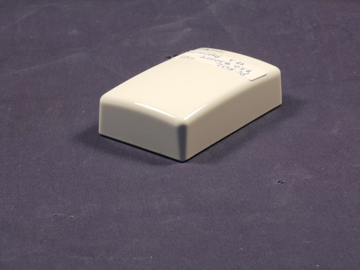
GTC202124TXR
Sep 18, 2013Repeater
Equipment Class
DXX - Part 15 Low Power Communication Device Transmitter
GTC202516TXR
Mar 19, 2013Lamp Controller
Equipment Class
DXX - Part 15 Low Power Communication Device Transmitter