GTC202153TXRBattery Powered Thermostat
Honeywell International Inc.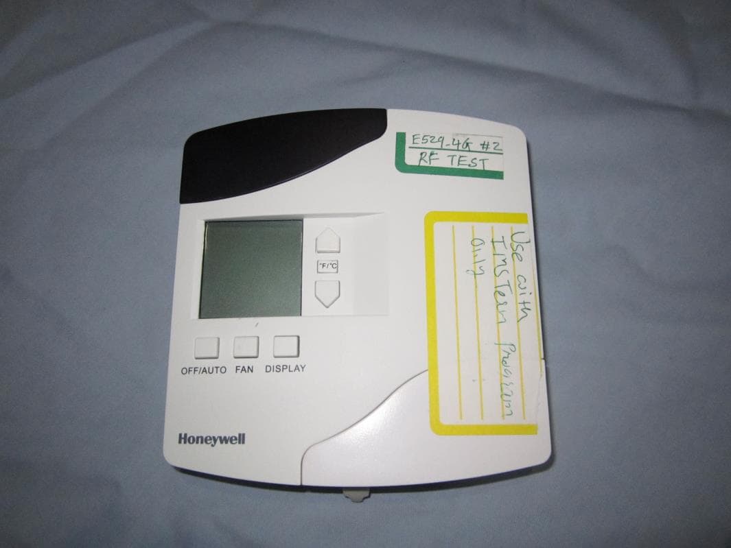
Click to zoom
Application Details
- Equipment Class
- DXX - Part 15 Low Power Communication Device Transmitter
- Date of Grant
- Aug 27, 2014
- Application Purpose
- Original Equipment
- Date of Application
- Aug 26, 2014
- Equipment Note
- Battery Powered Thermostat
- Frequency Range
- 2400.00000000 - 2483.50000000
- Company
- Honeywell International Inc.
- Country
- United States
Documents & Files
Document Text
Text extracted from the exhibit documents filed with the FCC. Open a document above to read the original.
Users Manual
PN 292-120 Copyright 2013 INNCOM by Honeywell E529.RF Thermostat Installation Guide The e529.RF battery- operated thermostat is designed to work in conjunction with an HVAC controller to monitor and maintain room temperature (other devices may also be controlled from the e529.RF). There are three general scenarios for using the e529.RF: A basic IRAS application with the e529.RF communicating wirelessly to another device An IRAS application with RF communication to a network backbone An IRAS application with wired communication to a network backbone Installation CAUTION! The e529.RF is intended for indoor use only. The E529.RF installer must be a trained, experienced service technician. All wiring must comply with local codes and ordinances. Failure to follow the instructions provided with the product could damage the product or cause a hazardous condition. Placement Without the need for power input, the e529.RF affords great placement options for optimal performance with virtually any fan coil unit, heat pump, or packaged terminal air conditioner found in guestrooms. Since RF is critical to the e529.RF’s operation, placement of the device and careful consideration of possible sources of radio interference are important. For instance, the unit should not be placed close to floor or ceiling or near pipe or other metal pieces. To minimize external conditions interference with room temperature measurement, locate the e529.RF away from external doors or windows and areas in direct sunlight. Mounting Instructions Separate the e529.RF body and the mounting plate by pulling the bottom of the mounting plate away from the e529.RF body and then pull the mounting plate down. NOTE: If the back- mounting plate is rotated more than 2 or 3 degrees, the plastic tabs at the top of the plate may fracture or break off. Attach the mounting plate to the wall or electrical box with the arrow embossed on the mounting plate pointing upward. The e529.RF is provided with four 6-32 ¾” sheet metal screws for mounting the plate to an existing 4” × 4” electrical box. If attaching the mounting plate to sheetrock or a similar wall surface, install four 6-8 × ¾ anchors. The four holes on the mounting plate can be used to mark the location for the anchors. Install the four AA alkaline batteries (NOTE: Use alkaline batteries only) provided into the battery compartment located on the rear of the e529.RF. Depress the battery clamp latch at the top of the battery compartment and then swing open the battery clamp. Insert the 4 AA alkaline batteries, matching the “+” terminals on the batteries to the “+” symbols in the battery compartment. Close the battery clamp and verify the latch is securely fastened. Verify that the e529.RF display is now showing information. If the display is blank, verify that the batteries are completely installed with the right polarities and that the batteries are not dead. ! PN 292-120 2 Copyright 2013 INNCOM by Honeywell Hook the tabs at the top rear of the e529.RF housing into the matching depressions at the top of mounting plate and rotate the bottom of the e529.RF housing toward the wall until it snaps into the place on the mounting plate. Secure the e529.RF housing to the mounting plate with the two small screws provided with the e529.RF. The screws thread into two small holes on the bottom of the e529.RF housing (see figure above). Service Mode The installation technician must enters the e529.RF’s Service Mode to set parameters for uniquely identifying a room, binding the INNCOM devices in the room to that identity, setting the operational characteristics of the devices, and, if necessary, connecting the room to floor- or building- wide network. Entering Service Mode To enter Service Mode 1. Press and hold the °F/°C button on the e529.RF 2. Press and release the OFF/AUTO button 3. Press and release the DISPLAY button 4. Release the °F/°C button Entering Values in Service Mode rId— Sets Room ID, a number that uniquely identifies the room to other device or on a network. Room ID consists of 5 digits divided into 3 bytes of data labeled HI_MED_LO (default is 6_55_35). The number will be included on the commissioning list and generally corresponds to the actual room number. o Enter Service Mode o At rId, press OFF/AUTO; the Room ID scrolls across the LCD, then the first digit (HI) appears o Use the UP/DOWN arrow to scroll to the first number of the Room ID entry from the commissioning list (HI values can be from 0 to 6) o Accept the HI number by pressing DISPLAY. The MED value will now show on the LCD o Enter the MED 2 digits in the same manner (value 0–99). LCD shows LO o Enter the LO 2-digit value (0–99). On pressing DISPLAY, the new rId will scroll across the LCD, then the e529.RF returns to the menu list PAn—The ID number of a network coordinating device, e.g., a B574, in a network bridge application. The number will be included on the commissioning list. o Enter Service Mode if not already there o Scroll to PAn and press OFF/AUTO o Use the UP/DOWN arrows to find the PAN ID on the commissioning list o Press DISPLAY. The e529.RF beeps to confirm the Pan ID value is stored, and the LCD returns to the menu list rF—Selects the RF channel for IRAS communication. The number will be included on the commissioning list. o Enter Service Mode if not already there o Scroll to rF and enter using OFF/AUTO o Use UP/DOWN to set the RF channel between 11 and 26 o Press DISPLAY. The e529.RF beeps to confirm the value is stored and the LCD returns to menu Adr—Used to “teach” IRAS devices the unique identification information (e.g., Room ID, PAN ID, I/O map for a room) that binds them to a room or network. o Enter Service Mode if not already there o Scroll to Adr and enter using OFF/AUTO o Prepare the partner device to learn from the e529.RF o Scroll to the Address for the device to be taught (from the commissioning list) o Press DISPLAY. The unit will send the teach command on al…
Text truncated - open the document above for the full version.
Cover Letter(s)
To: Federal Communications Commission 7435 Oakland Mills Road Columbia, MD 21046-1609 Curtis-Straus LLC TCB One Distribution Center Circle, #1 Littleton, MA 02702 Re: Confidentiality Request Gentlemen: This letter is to comply with 47 CFR 0.457(d)(2) pertaining to confidential material. INNCOM by Honeywell requests that the following documents regarding this submission for FCC ID GTC202153TXR be kept confidential: 1. Schematics 2. Block Diagram 3. Circuit/Technical Description The material above contains technical data, which would customarily be guarded from competitors. Sincerely, Ryan Gardner Engineering Manager INNCOM by Honeywell 6/10/2014
Cover Letter(s)
Agent’s Authorization Letter 04/21/2014 I, an officer of INNCOM by Honeywell. do hereby authorize, until further notice, Chris Reynolds of Curtis-Straus LLC, One Distribution Center Circle, #1, Littleton, MA 01460, to act on our behalf in dealings before the Federal Communications Commission with respect to all matters relating to equipment authorizations under 47 CFR. This authorization includes, but is not limited to, the signing of Form 731. I certify that no party (as defined in 47 CFR 1.2002) to this application, including myself, is subject to a denial of federal benefits, that include FCC benefits, pursuant to section 5301 of the Anti-Drug Abuse Act of 1988, 21 U.S.C., 853A. Certified By: __________________ Ryan Gardner Engineering Manager INNCOM by Honeywell 06/10/2014
Test Report
Curtis-Straus LLC is accredited by the American Association for Laboratory Accreditation for the specific scope of accreditation under Certificate Number 1627-01. This report may contain data which is not covered by the A2LA accreditation. ____________________________________________________________ Curtis-Straus LLC, a wholly owned subsidiary of BV CPS One Distribution Center Circle, #1 Littleton, MA TEL (978) 486-8880 FAX (978) 486-8828 page 1 of 17 Test Report Curtis-Straus LLC, a wholly owned subsidiary of BV CPS Report No EN1170-1 Client Inncom Ryan Gardner Address 277 West Main Street Niantic, CT 06357 Phone 860-739-4468 Items tested E529 Battery Powered Thermostat FCC ID GTC202153TXR IC ID 1609A-202153TXR FRN 0017924150 Equipment Type Low Power Communication Device Transmitter Equipment Code DXX Emission Designator 2M49G1D Standards 47CFR 15.249, RSS 210 Issue 8 and RSS GEN Issue 3 Test Dates September 10, 12, 13, & 25, 2013 and May 19, 2014 Results As detailed within this report Prepared by Tuyen Truong – Test Engineer Authorized by Christopher Reynolds – EMC Supervisor Issue Date 6/20/2014 Conditions of Issue This Test Report is issued subject to the conditions stated in the ‘Conditions of Testing’ section on page 16 of this report. Test Report for Inncom Report No. EN1170-1 June 20, 2014 ______________________________________________________________________ ____________________________________________________________ Curtis-Straus LLC, a wholly owned subsidiary of BV CPS One Distribution Center Circle, #1 Littleton, MA TEL (978) 486-8880 FAX (978) 486-8828 page 2 of 17 Contents Contents .................................................................................................................................. 2 Product Tested - Configuration Documentation ....................................................................... 3 Summary ................................................................................................................................. 4 Test Methodology ................................................................................................................ 4 Compliance Statement ............................................................................................................ 5 Test Results ............................................................................................................................ 6 Fundamental Measurements................................................................................................ 6 Radiated Spurious Emissions .............................................................................................. 8 AC Line Conducted Emissions ........................................................................................... 12 Duty Cycle Correction Calculation ...................................................................................... 13 Occupied Bandwidth .......................................................................................................... 14 Measurement Uncertainty...................................................................................................... 15 Conditions Of Testing ............................................................................................................ 16 Form Final Report REV 2-16-07 (DW) Test Report for Inncom Report No. EN1170-1 June 20, 2014 ______________________________________________________________________ Issue No. Reason for change Date Issued 1 Original Release June 20, 2014 _____________________________________________________________ Curtis-Straus LLC, a wholly owned subsidiary of BV CPS One Distribution Center Circle, #1 Littleton, MA TEL (978) 486-8880 FAX (978) 486-8828 page 3 of 17 Product Tested - Configuration Documentation EUT Configuration Work Order: N1170 Company: Inncom Company Address: 277 West Main Street Niantic, CT 06357 Contact: Ryan Gardner MN SN EUT: E529 not listed EUT Description: E529 Battery Powered Thermostat EUT Tx Frequency: 2405-2480MHz Support Equipment: MN SN X529 Application Tester X529 Not Listed X529 RF X529.RF Not Listed EUT Ports: Port Label Port Type No. of ports No. Populated Cable Type Shielded Ferrites Length Max Length In/Out NEBS Type Unpopulated Reason ISP Signal 1 0 Setup only H1 Signal 1 0 Not Used Software / Operating M ode Description: EUT is transmitting to X529.RF Test Report for Inncom Report No. EN1170-1 June 20, 2014 ______________________________________________________________________ Issue No. Reason for change Date Issued 1 Original Release June 20, 2014 _____________________________________________________________ Curtis-Straus LLC, a wholly owned subsidiary of BV CPS One Distribution Center Circle, #1 Littleton, MA TEL (978) 486-8880 FAX (978) 486-8828 page 4 of 17 Summary This test report supports an application for certification of a transmitter operating pursuant to 47 CFR 15.249, RSS GEN Issue 3, and RSS-210, Issue 8. The product is the E529 Battery Powered Thermostat. It is a transmitter that operates in the range 2400 – 2483.5 MHz. We found that the product met the above requirements. The test sample was received in good condition. Test Methodology Radiated emission and AC Line conducted testing was performed according to the procedures specified in ANSI C63.4 (2003) and RSS-GEN. Radiated Emissions were maximized by rotating the device around three orthogonal axes as well as varying the test antenna’s height and polarity. The device antenna cannot be maximized separately. The product was tested with modulation on and peak readings were compared against the average limit presented in section CFR 15.249. The EUT operating voltage is 6VDC. The following bandwidths were used during radiated spurious and line conducted emissions. Frequency RBW VBW 0.15-30MHz 9kHz 30kHz 30-1000MHz 120kHz 1MHz 1-25GHz 1MHz 3MHz Test Report for Inncom Report No. EN1170-1 June 20, 2014 _______________________________…
Text truncated - open the document above for the full version.
Test Setup Photos
EMI-Radiated – Fundamental Measurement, EMI Spurious, Occupied BW
Contact Information
Applicant
Jeanne Enaux(Sr. Quality Engineering Manager)
Test Firm
BUREAU VERITAS CONSUMER PRODUCTS SERVICES, INC.Ozgur Ozturk
[email protected]978-486-8880
Technical Specifications
| # | Rule Parts | Frequency Range | Power Output |
|---|---|---|---|
| 1 | 15C | 2.40 GHz - 2.48 GHz | 6.83 mW |
Other Applications from Honeywell International Inc.
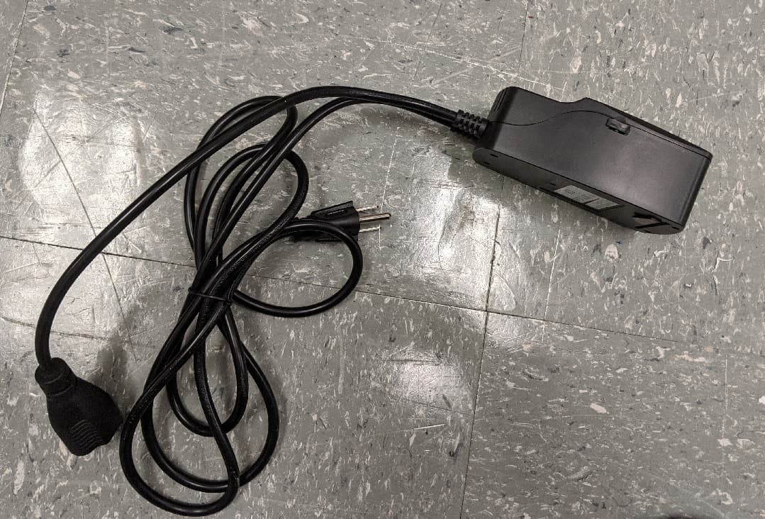
GTC-201705X
Mar 22, 2021L510 Lamp Controller
Equipment Class
DTS - Digital Transmission System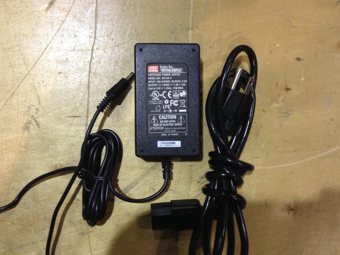
GTC201104TXR
Aug 26, 2014B578 Ethernet to RF Protocol Converter
Equipment Class
DXX - Part 15 Low Power Communication Device Transmitter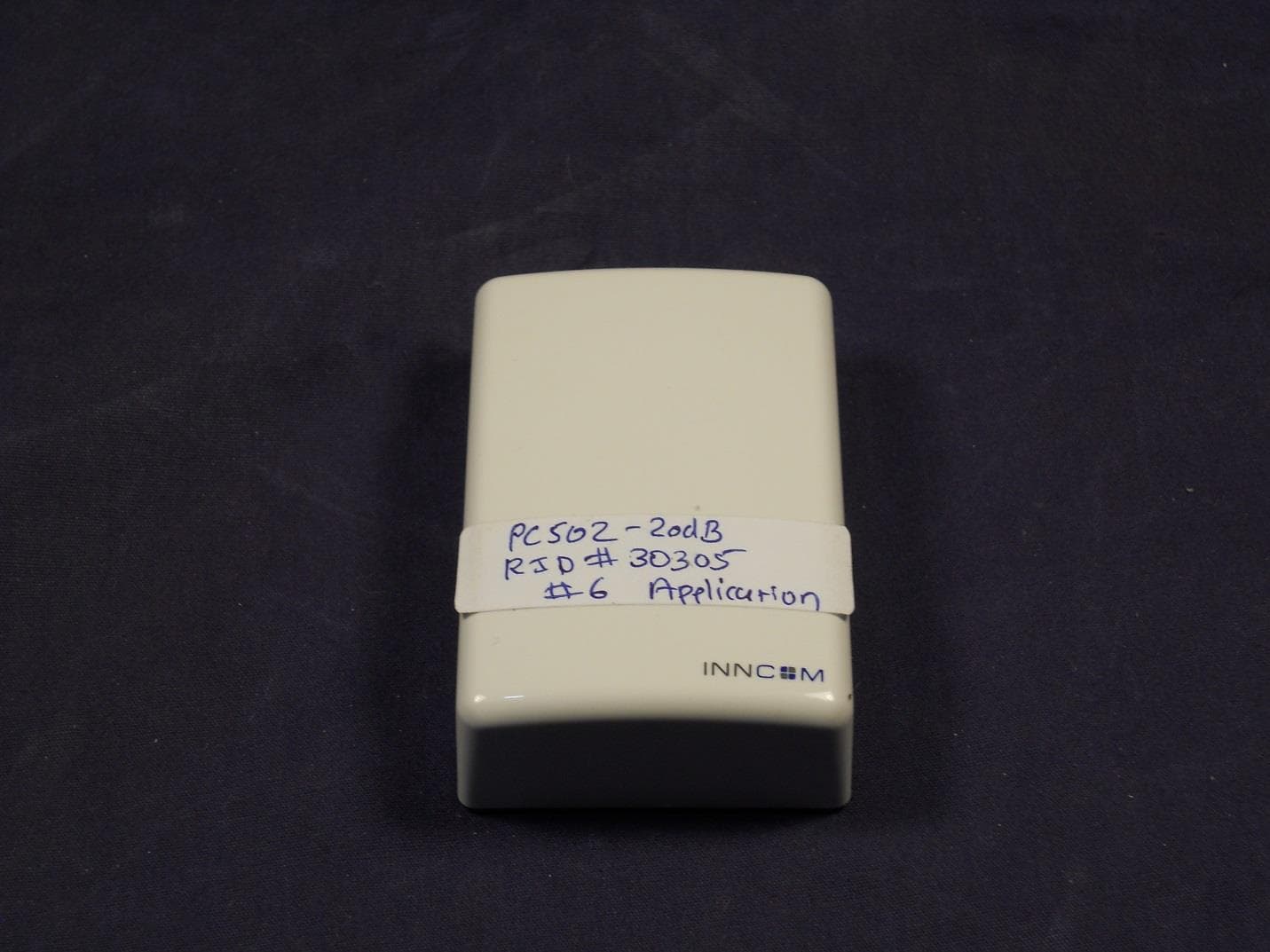
GTC202125TXR
Aug 17, 2014Wireless Repeater Module
Equipment Class
DTS - Digital Transmission System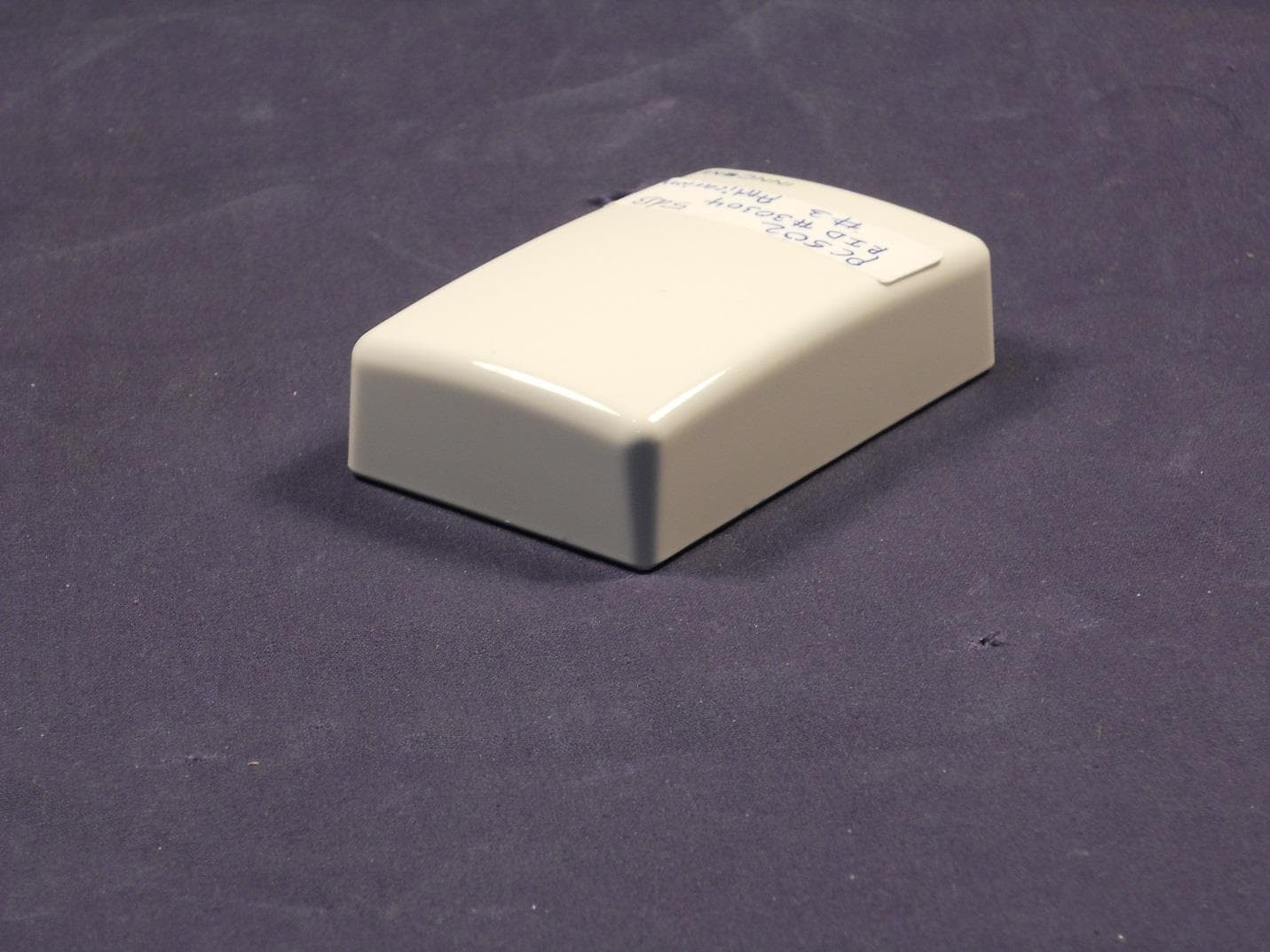
GTC202124TXR
Sep 18, 2013Repeater
Equipment Class
DXX - Part 15 Low Power Communication Device Transmitter
GTC202516TXR
Mar 19, 2013Lamp Controller
Equipment Class
DXX - Part 15 Low Power Communication Device Transmitter