GTC201104TXRB578 Ethernet to RF Protocol Converter
Honeywell International Inc.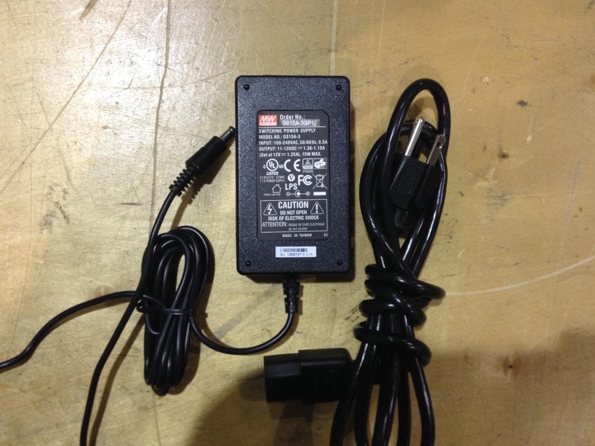
Click to zoom
Application Details
- Equipment Class
- DXX - Part 15 Low Power Communication Device Transmitter
- Date of Grant
- Aug 26, 2014
- Application Purpose
- Original Equipment
- Date of Application
- Aug 26, 2014
- Equipment Note
- B578 Ethernet to RF Protocol Converter
- Frequency Range
- 2400.00000000 - 2483.50000000
- Company
- Honeywell International Inc.
- Country
- United States
Documents & Files
Document Text
Text extracted from the exhibit documents filed with the FCC. Open a document above to read the original.
Users Manual
1 Copyright 2014 INNCOM by Honeywell INNCOM B578 Datasheet Overview INNCOM’s multifunctional controller works in three configurations to facilitate different Integrated Room Automation System (IRAS) operations: As the B578S Edge Router, it networks Ethernet to INNCOM’s Deep Mesh RF network. It provides backhaul networks with up to 200* rooms per PAN ID. It supports multiple IP protocols (UDP, ICMP). The expanded addressing facilitates transport reliability and multicasting. The Edge Router enhances security and offers RF-to-Ethernet protocol conversion, with the availability of a PoE power supply for Power over Ethernet applications. As the B578N, the Edge Router interfaces with the Tridium Niagara JACE (Java Application Control Engine) controller to provide connectivity to numerous common network protocols such as LonWorks and BACNet, as well as proprietary networks. As the PC-803, the device acts as a protocol converter, converting in-room RF traffic to Ethernet towards the server. Note: The device will generally be referred to as the “B578” throughout this document. Statements specific to a particular configuration will be noted accordingly. Features Supports CBL32 control algorithms RS485 System Interface dongle 10MBit Ethernet Available in PoE and +12VDC powered models 128 bit AES encryption (Ethernet link and RF network) Typical indoor RF range up to 100ft Supports 2.4Ghz IEEE 802.15.4 compliant RF transceiver Supports S5bus (through external adapter) Compact physical dimension DIN rail mounting option (Figure 1) Wall or ceiling mount on standard 2-gang ring (Figure 2) Supports up to 200 rooms depending on the guestroom application deployed and the selected RF environment at the site. 4 kBytes mailbox memory usable as a relay-buffer for battery operated devices (Edge Router) IPv6 support (Edge Router) * The 200 device limit is based on timing considerations used by the communication protocols of a Deep Mesh network. Local RF interference sources, conditions, and device placement can decrease this number. Figure 2 B578 Wall/Ceiling Mountable Figure 1 B578 DIN 2 Copyright 2014 INNCOM by Honeywell Specifications Parameter B578 RF Data Rate 250kbps Indoor/Urban RF range 100ft RF Transmit Power 50mW (+17dBm) RF Receive Sensitivity -97.7dBm Frequency Band 2.4Ghz Encryption AES-128 Protocol 802.15.4 Frequency Channels 11–26 Network Topology Mesh Maximum devices per IP network segment 50 B578 PAN coordinators; 2000 PC-803 room gateways; 200 Edge Routers Maximum devices per RF mesh network Up to 200 (depending on application profile and site situation) Maximum in-room devices per room Up to 50 Supply Voltage 12VDC Current Consumption 200mA peak, 100mA RMS Operating Ambient Temperature 0–40 °C Dimensions 86mm x 78mm x 40mm (DIN rail mount); 20.65mm x 22.25mm (wall mount) Agency Approvals FCC Part 15, CE Mark ETSI, RoHS This device contains FCC ID: GTC201104TXR. This device complies with part 15 of the FCC Rules. Operation is subject to the following two conditions: (1) This device may not cause harmful interference, and (2) this device must accept any interference received, including interference that may cause undesired operation. This equipment has been tested and found to comply with the limits for a Class B digital device, pursuant to Part 15 of the FCC Rules. These limits are designed to provide reasonable protection against harmful interference in a residential installation. This equipment generates, uses, and can radiate radio frequency energy and, if not installed and used in accordance with the instructions, may cause harmful interference to radio communications. However, there is no guarantee that interference will not occur in a particular installation. If this equipment does cause harmful interference to radio or television reception, which can be determined by turning the equipment off and on, the user is encouraged to try to correct the interference by one of the following measures: Reorient or relocate the receiving antenna. Increase the separation between the equipment and receiver. Connect the equipment into an outlet on a circuit different from that to which the receiver is connected. Consult the dealer or an experienced radio/TV technician for help. Modifications not expressly approved by INNCOM International Inc. could void the user’s authority to operate the equipment. 3 Copyright 2014 INNCOM by Honeywell Mounting Considerations The B578 Network Controllers are designed for mounting in a variety of applications. The bottom housing is equipped with a channel and tab for DIN rail mounting and therefore does not require any additional screws or hardware for installation. For screw-mounted applications, there are 4 countersunk holes located in the bottom housing that can be accessed by removing the top cover and Printed Circuit Board Assembly (PCBA). Figure 3 B578 Network The B578 can be attached to an X-type DIN rail. To attach the B578 to a DIN rail, pull the tab (Figure 3) down and attach the bottom of the housing to the DIN rail (always mount the DIN rail with the tab at the bottom). Once the unit is sitting flush on the rail, release the tab. To remove the B578 from the DIN rail, pull the tab down and lift the bottom edge of the unit off the DIN rail first. This ensures that the cable, cable channels, and connections are always aligned in the correct orientation in a daisy-chained application. Please note that the above picture is from the INNCOM QC lab. In field deployment, B578s will typically be distributed throughout the building. Figure 2 DIN Rail Mounting 4 Copyright 2014 INNCOM by Honeywell Figure 4 Top Housing Removal To gain access to headers and connectors located on the PCBA, remove the B578 from the DIN rail or NEMA box enclosure. Using a flat screw driver, lift the top housing away from the snap tangs on the bottom housing. Figure 5 Mounting Screw Locations To screw mount the B578, open the B578 as described above and…
Text truncated - open the document above for the full version.
Cover Letter(s)
To: Federal Communications Commission 7435 Oakland Mills Road Columbia, MD 21046-1609 Curtis-Straus LLC TCB One Distribution Center Circle, #1 Littleton, MA 02702 Re: Confidentiality Request Gentlemen: This letter is to comply with 47 CFR 0.457(d)(2) pertaining to confidential material. INNCOM by Honeywell requests that the following documents regarding this submission for FCC ID GTC201104TXR be kept confidential: 1. Schematics 2. Block Diagram 3. Circuit/Technical Description The material above contains technical data, which would customarily be guarded from competitors. Sincerely, Ryan Gardner Engineering Manager INNCOM by Honeywell 4/21/2014
Cover Letter(s)
Agent’s Authorization Letter 04/21/2014 I, an officer of INNCOM by Honeywell. do hereby authorize, until further notice, Chris Reynolds of Curtis-Straus LLC, One Distribution Center Circle, #1, Littleton, MA 01460, to act on our behalf in dealings before the Federal Communications Commission with respect to all matters relating to equipment authorizations under 47 CFR. This authorization includes, but is not limited to, the signing of Form 731. I certify that no party (as defined in 47 CFR 1.2002) to this application, including myself, is subject to a denial of federal benefits, that include FCC benefits, pursuant to section 5301 of the Anti-Drug Abuse Act of 1988, 21 U.S.C., 853A. Certified By: __________________ Ryan Gardner Engineering Manager INNCOM by Honeywell 04/21/2014
ID Label/Location Info
FCC ID: GTC201104TXR IC ID: 1609A-202153TXR
Test Report
Curtis-Straus LLC is accredited by the American Association for Laboratory Accreditation for the specific scope of accreditation under Certificate Number 1627-01. This report may contain data which is not covered by the A2LA accreditation. ____________________________________________________________ Curtis-Straus LLC, a wholly owned subsidiary of BV CPS One Distribution Center Circle, #1 Littleton, MA TEL (978) 486-8880 FAX (978) 486-8828 page 1 of 17 Test Report Curtis-Straus LLC, a wholly owned subsidiary of BV CPS Report No EO0953-1 Client InnCom Ryan Gardner Address 277 West Main Street Niantic, CT 06357 Phone 860-739-4468 Items tested B578 FCC ID IC ID GTC201104TXR 1609A-201104TXR FRN 0017924150 Equipment Type Low Power Communication Device Transmitter Equipment Code DXX Standards 47CFR 15.249,RSS 210 Issue 8, RSS GEN Issue 3 Test Dates April 21 – 23, 2014 and May 19, 2014 Results As detailed within this report Prepared by Tuyen Truong A. – Test Engineer Authorized by Christopher Reynolds – EMC Supervisor Issue Date 6/17/2014 Conditions of Issue This Test Report is issued subject to the conditions stated in the ‘Conditions of Testing’ section on page 16 of this report. Test Report for InnCom Report No. EO0953-1 June 12, 2014 ______________________________________________________________________ ____________________________________________________________ Curtis-Straus LLC, a wholly owned subsidiary of BV CPS One Distribution Center Circle, #1 Littleton, MA TEL (978) 486-8880 FAX (978) 486-8828 page 2 of 17 Contents Contents .................................................................................................................................. 2 Product Tested - Configuration Documentation ....................................................................... 3 Summary ................................................................................................................................. 4 Test Methodology ................................................................................................................ 4 Compliance Statement ............................................................................................................ 5 Test Results ............................................................................................................................ 6 AC Line Conducted Emission Measurements ...................................................................... 6 Fundamental Measurements................................................................................................ 7 Radiated Spurious Emissions ............................................................................................ 10 Duty Cycle Correction Calculation ...................................................................................... 12 Occupied Bandwidth .......................................................................................................... 13 Conditions Of Testing ............................................................................................................ 16 Form Final Report REV 2-16-07 (DW) Test Report for InnCom Report No. EO0953-1 June 12, 2014 ______________________________________________________________________ Issue No. Reason for change Date Issued 1 Original Release June 12, 2014 _____________________________________________________________ Curtis-Straus LLC, a wholly owned subsidiary of BV CPS One Distribution Center Circle, #1 Littleton, MA TEL (978) 486-8880 FAX (978) 486-8828 page 3 of 17 Product Tested - Configuration Documentation EUT Configuration Work Order: O0953 Company: Inncom Company Address: 277 West Main Street Niantic, CT 06357 Contact: Ryan Gardner Person Present: Ryan Gardner, Ravi MN SN EUT: 201-104 #1 MW Switching Power Supply GS15A-3 -- EUT Description: B578 Ethernet to RF Protocol Converter EUT Max Frequency: 32 MHz EUT Min Frequency: 8 MHz EUT TX Frequency: 2400 - 2483.5MHz Support Equipment: MN SN Dell PC Dimension 4550 00920 Dell LCD Monitor Ultrasharp -- Keyboard RTD20 -- Mouse M028U 23060285086 EUT Ports: Port Label Port Type No. of ports No. Populated Cable Type Shielded Ferrites Length Max Length In/Out NEBS Type Comments AD/DC Power Power Input 1 1 3-wires to 2-wires No No 3m >3m Indoor Ethernet RJ45 1 1 cat5 No No 10m 100m Indoor Not configured in RF sample IMS Terminal Terminal 1 0 Only for Setup ES1 Header 5pin 1 0 Not used at this time Software / Operating M ode Description: EUT is set to transmit on Low, Mid and High channels from 2.4 to 2.4835GHz frequency range. Test Report for InnCom Report No. EO0953-1 June 12, 2014 ______________________________________________________________________ Issue No. Reason for change Date Issued 1 Original Release June 12, 2014 _____________________________________________________________ Curtis-Straus LLC, a wholly owned subsidiary of BV CPS One Distribution Center Circle, #1 Littleton, MA TEL (978) 486-8880 FAX (978) 486-8828 page 4 of 17 Summary This test report supports an application for certification of a transmitter operating pursuant to 47 CFR 15.249. The product is B578. It is a transmitter that operates in the range 2402 - 2480MHz. We found that the product met the above requirements. The test samples were received in good condition. Test Methodology Radiated emission testing was performed according to the procedures specified in ANSI C63.4 (2003) and RSS-GEN. Radiated Emissions were maximized by rotating the device around three orthogonal axes (x, y and z) as well as varying the test antenna’s height and polarity. The device antenna cannot be maximized separately. AC Main conducted emission was performed with a 50Ω/50μH LISN. The product was tested with modulation on and peak readings were compared against the average limit presented in section CFR 15.249. The EUT operating voltage is 120Vac/60Hz. The following bandwidths were used during radiated spurious and line conducted emissions. F…
Text truncated - open the document above for the full version.
Contact Information
Applicant
Jeanne Enaux(Sr. Quality Engineering Manager)
Test Firm
BUREAU VERITAS CONSUMER PRODUCTS SERVICES, INC.Ozgur Ozturk
[email protected]978-486-8880
Technical Specifications
| # | Rule Parts | Frequency Range | Power Output |
|---|---|---|---|
| 1 | 15C | 2.40 GHz - 2.48 GHz | 29.80 mW |
Other Applications from Honeywell International Inc.
GTC-201705X
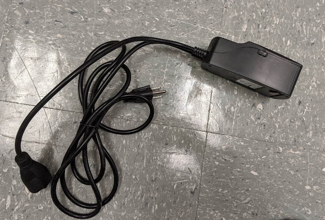
Mar 22, 2021L510 Lamp Controller
Equipment Class
DTS - Digital Transmission System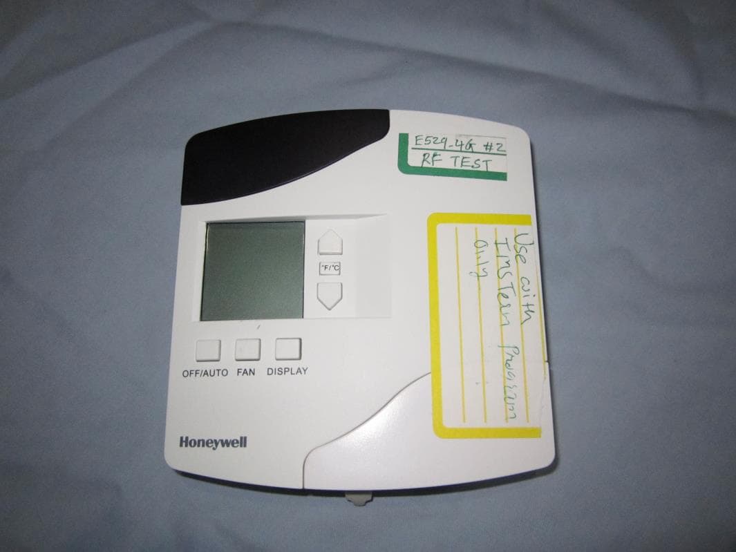
GTC202153TXR
Aug 27, 2014Battery Powered Thermostat
Equipment Class
DXX - Part 15 Low Power Communication Device Transmitter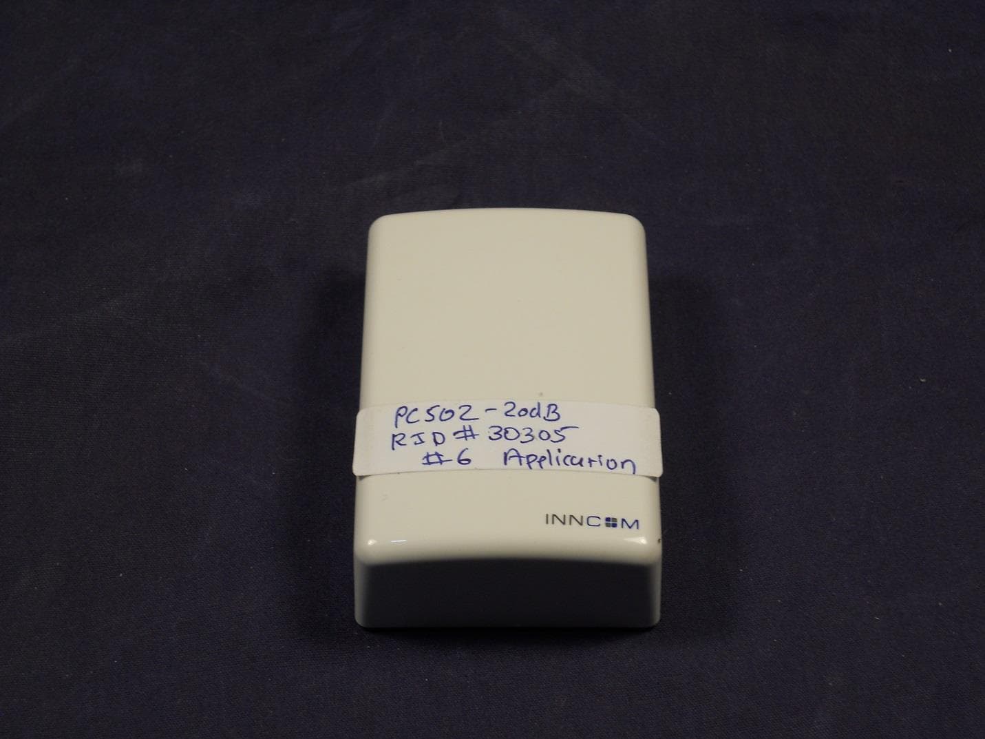
GTC202125TXR
Aug 17, 2014Wireless Repeater Module
Equipment Class
DTS - Digital Transmission System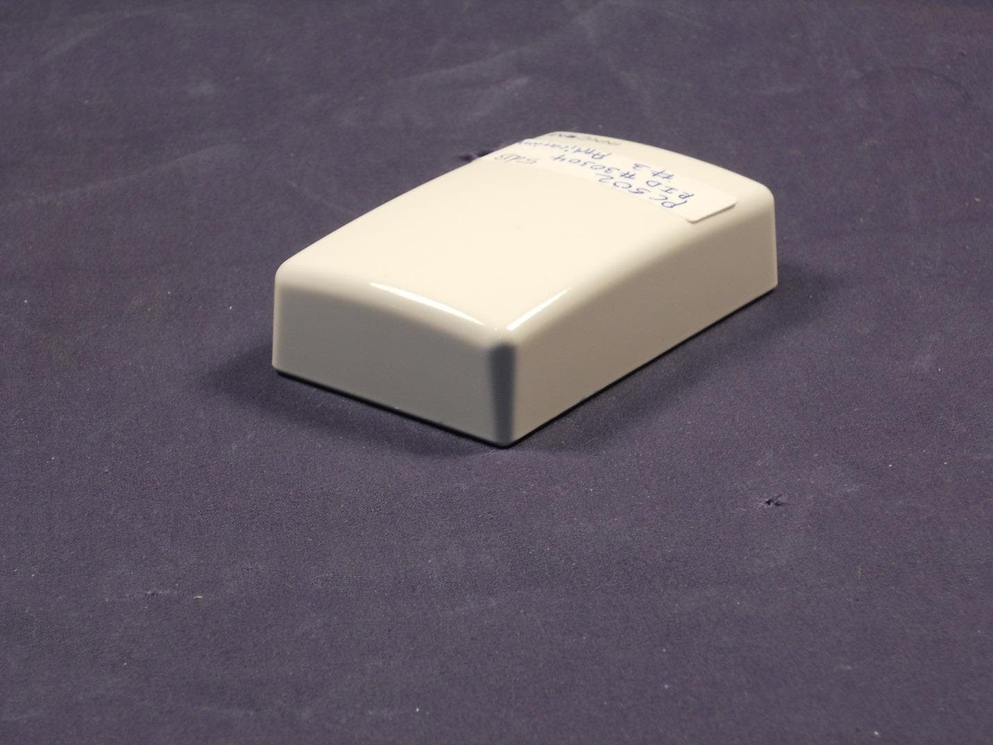
GTC202124TXR
Sep 18, 2013Repeater
Equipment Class
DXX - Part 15 Low Power Communication Device Transmitter
GTC202516TXR
Mar 19, 2013Lamp Controller
Equipment Class
DXX - Part 15 Low Power Communication Device Transmitter