GXZE10647Remote Control Transmitter
Telemotive Industrial Controls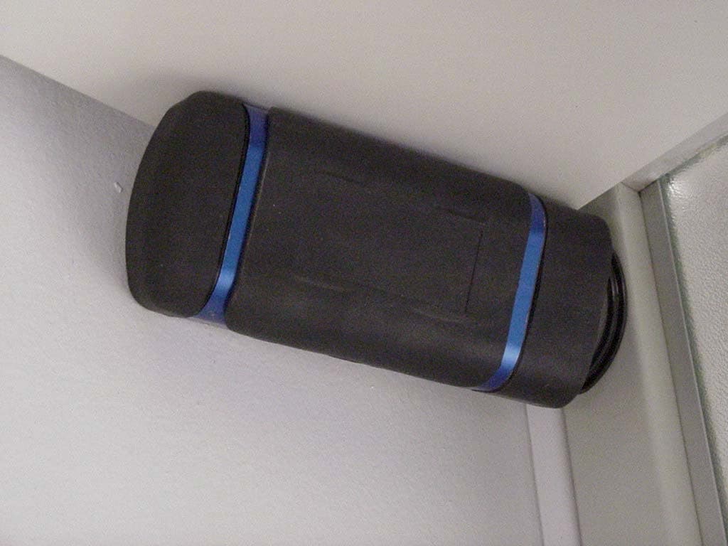
Click to zoom
Application Details
- Equipment Class
- DSC - Part 15 Security/Remote Control Transmitter
- Date of Grant
- Oct 25, 2001
- Application Purpose
- Original Equipment
- Date of Application
- Oct 25, 2001
- Equipment Note
- Remote Control Transmitter
- Frequency Range
- 433.10000000 - 439.80000000
- Country
- United States
Documents & Files
Document Text
Text extracted from the exhibit documents filed with the FCC. Open a document above to read the original.
Users Manual
TR12 AND TX12 10/19/2001 I I N N S S T T A A L L L L A A T T I I O O N N A A N N D D U U S S E E R R S S M M A A N N U U A A L L TELEMOTIVE telePilot TM SERIES TR12 AND TX12 R R A A D D I I O O C C O O N N T T R R O O L L S S Y Y S S T T E E M M telemotive ® Industrial Controls 175 Wall Street Glendale Heights, IL 60139-1985 Phone: 630-582-1111, Toll Free: 888-687-4400 Website: www.telemotive.com This page intentionally left blank. Table of Contents 1 1- Service Information...........................................................................................................................2 2- Radio Controlled Safety ....................................................................................................................3 3- General System Information .............................................................................................................9 4- Installation Procedure......................................................................................................................11 5- Operation ..................................................................................................................14 6- Wiring Diagram...............................................................................................................................18 7- Programming ...................................................................................................................................21 8- Servicing .........................................................................................................................................21 9- Spare Parts.......................................................................................................................................29 Section 1 – Service Information 2 1-1. Service Information. For questions regarding service or technical information or ordering replacement parts, ask for Telemotive Customer Care. Telemotive’s normal business hours are Monday through Friday 8:00 AM to 5:00 PM Central Standard Time. After hours emergency technical service is available. For new product orders or quotations, ask for Telemotive Sales. Telemotive Industrial Controls 175 Wall Street Glendale Heights, IL 60139-1985 USA Telephone: (630) 582-1111 In the USA toll free: (888) 687-4400 Website: http://www.telemotive.com/ Manuals for downloading are available for many products at the Telemotive website. E-mail [email protected] Telemotive Fax Numbers: Main: (630) 582-1195 Sales: (630) 582-1204 Customer Care: (630) 582-1205 Section 2 – Radio Controlled Safety 3 2-1. Warnings, Cautions and Notes. Through out this document WARNING, CAUTION and NOTE statements have been deliberately placed to highlight items critical to the protection of personnel and equipment. WARNING – A warning highlights a essential operating or maintenance procedure, practice, etc. which if not strictly observed, could result in injury or death of personnel, or long term physical hazards. Warnings are highlighted as shown below: WARNING CAUTION – A caution highlights an essential operating or maintenance procedure, practice, etc. which if not strictly observed, could result in damage to, or destruction of equipment, or loss of functional effectiveness. Cautions are highlighted as shown below: CAUTION NOTE – A note highlights an essential operating or maintenance procedure, condition or statement. Notes are shown as below: NOTE WARNINGS, CAUTIONS AND NOTES SHOULD NEVER BE DISREGARDED. The safety rules in this section are not intended to replace any rules or regulations of any applicable local, state, or federal governing organizations. The following information is intended to be used in conjunction with other rules or regulations already in existence. It is important to read all of the safety information contained in this section before installing or operating the Radio Control System. 2-2. Critical Installation Considerations. WARNING ALL EQUIPMENT MUST HAVE A MAINLINE CONTACTOR INSTALLED AND ALL TRACKED CRANES AND SIMILAR EQUIPMENT MUST HAVE A BRAKE INSTALLED. FAILURE TO FOLLOW THIS WARNING COULD RESULT IN SERIOUS INJURY OR DEATH AND DAMAGE TO EQUIPMENT. WARNING ON ALL REMOTE CONTROLLED CRANES AN AUDIBLE AND/OR VISUAL WARNING MEANS MUST BE PROVIDED. THESE AUDIBLE AND/OR VISUAL WARNING DEVICES MUST MEET ALL GOVERNMENTAL REQUIRE- MENTS. FAILURE TO FOLLOW THIS WARN- ING COULD RESULT IN SERIOUS INJURY OR DEATH AND DAMAGE TO EQUIPMENT. WARNING REMOVE ALL ELECTRICAL POWER FROM THE CRANE OR MACHINERY BEFORE AT- TEMPTING ANY INSTALLATION PROCE- DURES. DE-ENERGIZE AND TAG OUT ALL SOURCES OF ELECTRICAL POWER BEFORE TOUCH TESTING ANY EQUIPMENT. FAILURE TO FOLLOW THIS WARNING COULD RESULT IN SERIOUS INJURY OR DEATH AND DAM- AGE TO EQUIPMENT. Section 2 – Radio Controlled Safety (Continued) 4 WARNING THE DIRECT OUTPUTS OF THIS PRODUCT ARE NOT DESIGNED TO INTERFACE DI- RECTLY TO TWO STATE SAFETY CRITICAL MAINTAINED FUNCTIONS, I.E., MAGNETS, VACUUM LIFTS, PUMPS, EMERGENCY EQUIPMENT, ETC. A MECHANICALLY LOCK- ING INTERMEDIATE RELAY SYSTEM WITH SEPARATE POWER CONSIDERATIONS MUST BE PROVIDED. FAILURE TO FOLLOW THIS WARNING COULD RESULT IN SERIOUS IN- JURY OR DEATH AND DAMAGE TO EQUIP- MENT. 2-3. General. Radio controlled overhead cranes and other material handling equipment operate in several directions. They are large, bulky pieces of equipment that handle heavy loads efficiently at high speeds. Quite frequently, the equipment is operated in areas where people are working on the floor below. The crane operator must exercise extreme caution at all times. Workers must constantly be alert to avoid accidents. The following rules have been included to indicate how your careful and thoughtful actions may prevent injuries, damage to equipment, or even save a life. If radio controlled material-handling equipment is operated from the cab, special care must be taken to secure the transmitter. Refer to section titled Section 2-10. Boarding The Crane for spe…
Text truncated - open the document above for the full version.
Block Diagram
telePilot Block Diagram POWER SUPPLY RF SYTHESIZER CPU MEMORY MAPPED IO DEVICE VCTCXO RF SWITCH KEYPAD FM DEVIATION ADJUST SWITCH LEDsOFF ON TX MASK BIT 10.000MHz 3.6864MHz XTAL IR PORT 3.6864MHz XTAL
External Photos
Exhibit C 1 telePilot External Front Photo Exhibit C 2 telePilot External Back Photo
ID Label/Location Info
MODEL # telePilot SERIAL # FOR SAFETY ALWAYS TURN UNIT “OFF” WHEN NOT BEING USED. NEVER STAND UNDERNEATH A LOAD. AVOID AND REPORT CONDI- TIONS WHICH APPEAR UNSAFE OR UNUSUAL. ALWAYS READ MANUAL BEFORE OPERATING. FCC ID: GXZE10647 MADE IN USA. THIS DEVICE COMPLIES WITH PART 15 OF THE FCC RULES. OPERA- TION IS SUBJECT TO THE FOLLOWING TWO CONDITIONS: (1) THIS DEVICE MAY NOT CAUSE HARMFUL INTERFERENCE, AND (2) THIS DEVICE MUST ACCEPT ANY INTERFERENCE RECEIVED, INCLUDING INTERFERENCE THAT MAY CAUSE UNDESIRED OPERATION.
Internal Photos
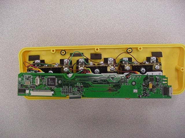
Exhibit C 3 telePilot Internal Front Photo Exhibit C 4 telePilot Internal Back Photo
Operational Description
Exhibit B 1 telePilot Operational Description The E10647-0 Radio Control Transmitter Unit is a hand-held unit with built-in antenna. The transmitter is powered by two AA batteries. The transmitter operates in 433 ñ 439.8 Mhz UHF frequency band on one of twenty-nine channels. The signal is direct frequency modulated and keyed-on in short bursts. The unit transmits when one of the controls is operated. The controls are manually operated and must be held in place to transmit a signal. The transmission ceases when the control is released. The antenna is a component on the printed circuit board. The unit is microprocessor controlled to provide logic for the synthesizer IC, keypad, LEDs, switches, and timing for Uarts for Data transmission and IR (infra-red) serial programming. The serial data output is fed to an analog switch that is switched between low and high deviation points set by a dual DAC(digital-to-analog converter). The DAC is fed to a VCTCXO running at 10.00MHz. The VCTCXO is fed into the synthesizer IC that produces the 433 ñ 439.8 Mhz UHF frequency band. Tune-up procedure: None, auto-tuned. Exhibit B 2 telePilot Block Diagram POWER SUPPLY RF SYTHESIZER CPU MEMORY MAPPED IO DEVICE VCTCXO RF SWITCH KEYPAD FM DEVIATION ADJUST SWITCH LEDsOFF ON TX MASK BIT 10.000MHz 3.6864MHz XTAL IR PORT 3.6864MHz XTAL Exhibit B 3
Contact Information
Applicant
Jim Mueller
Fax: 630-582-1217
Test Firm
Elite Electronic Engineering Co.Daniel Crowder
Technical Specifications
| # | Rule Parts | Frequency Range | Power Output |
|---|---|---|---|
| 1 | 15.231 | 433.1 MHz - 439.8 MHz | - |
Other Applications from Telemotive Industrial Controls
GXZE10738
Nov 10, 2003Remote Control Transmitter
Equipment Class
DSC - Part 15 Security/Remote Control Transmitter
GXZE10647B
Aug 14, 2002Remote Control Transmitter
Equipment Class
DSC - Part 15 Security/Remote Control Transmitter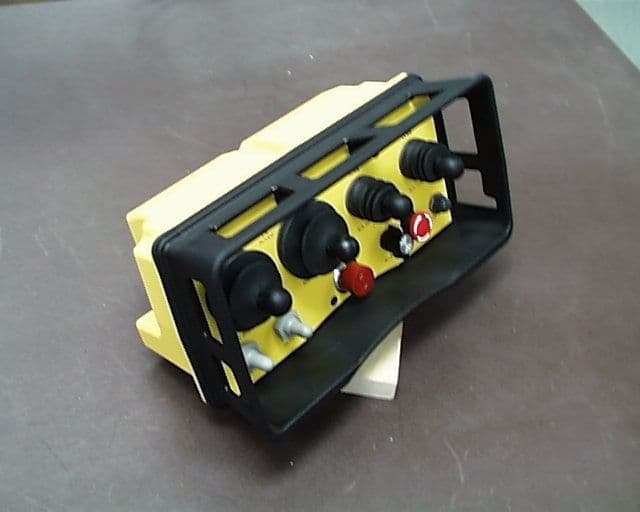
GXZE13653-JLTX
Oct 17, 1999Industrial Crane Remote Control
Equipment Class
DSC - Part 15 Security/Remote Control Transmitter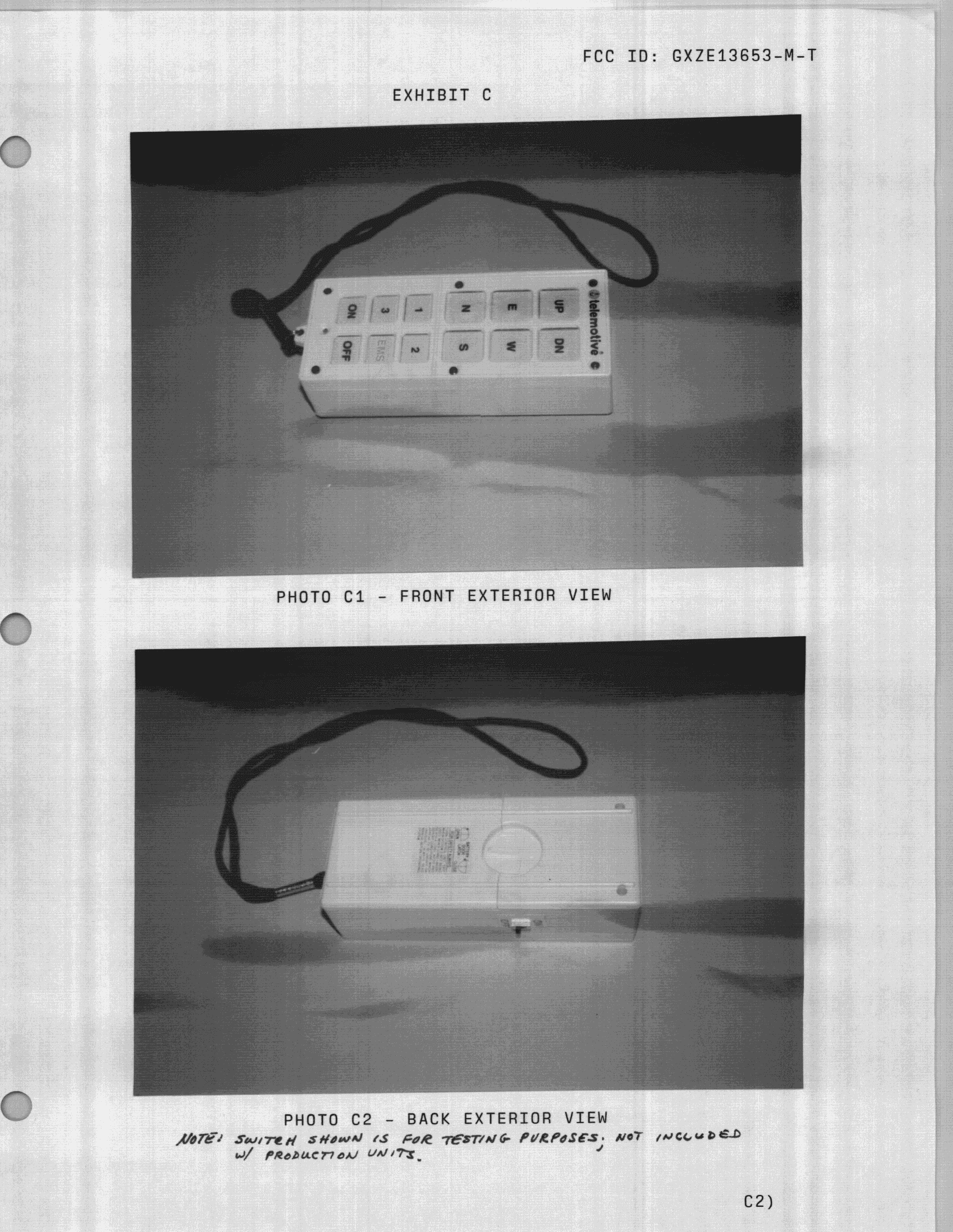
GXZE13653-M-T
Nov 29, 1998R/C Crane Transmitter
Equipment Class
DSC - Part 15 Security/Remote Control Transmitter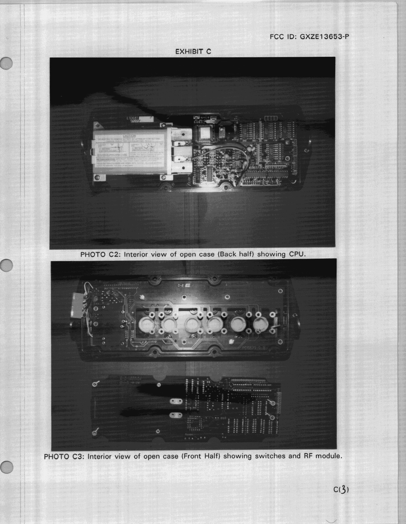
GXZE13653-P
Nov 03, 1998R/C Crane Transmitter
Equipment Class
DSC - Part 15 Security/Remote Control Transmitter