GXZE13653-JLTXIndustrial Crane Remote Control
Telemotive Industrial Controls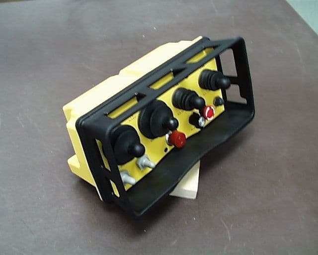
Click to zoom
Application Details
- Equipment Class
- DSC - Part 15 Security/Remote Control Transmitter
- Date of Grant
- Oct 17, 1999
- Application Purpose
- Original Equipment
- Date of Application
- Sep 26, 1999
- Equipment Note
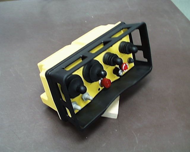
- Industrial Crane Remote Control
- Frequency Range
- 436.00000000 - 439.80000000
- Country
- United States
Documents & Files
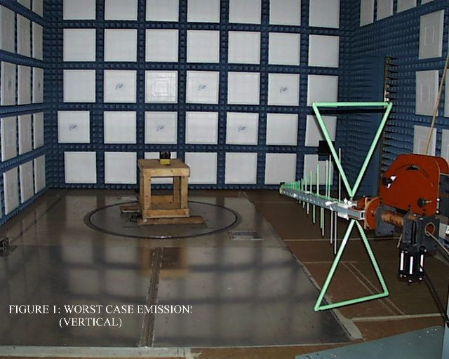
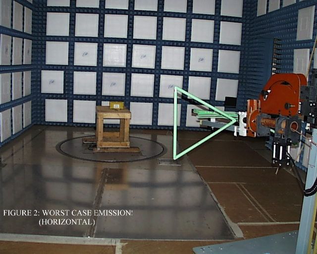
Document Text
Text extracted from the exhibit documents filed with the FCC. Open a document above to read the original.
Users Manual
Table of Contents i Section 1 - Service Information Heading . . . . . . . . . . . . . . . . . . . . . . . . . . . . . . . . . . . . . . . . . . . . . . . . . . . . . . . . . . . . . . . . . 1-1 1-1. Service Information . . . . . . . . . . . . . . . . . . . . . . . . . . . . . . . . . . . . . . . . . . . . . . . . . . . . . . . . . . . . . . . . . . . . . 1-1 Section 2 - Radio Controlled Crane Safety . . . . . . . . . . . . . . . . . . . . . . . . . . . . . . . . . . . . . . . . . . . . . . . . . . . . . . . . . . . . . . . . 2-1 2-1. Introduction . . . . . . . . . . . . . . . . . . . . . . . . . . . . . . . . . . . . . . . . . . . . . . . . . . . . . . . . . . . . . . . . . . . . . . . . . . . 2-1 2-2. General . . . . . . . . . . . . . . . . . . . . . . . . . . . . . . . . . . . . . . . . . . . . . . . . . . . . . . . . . . . . . . . . . . . . . . . . . . . . . . . 2-1 2-3. Persons Authorized To Operate Radio Controlled Cranes. . . . . . . . . . . . . . . . . . . . . . . . . . . . . . . . . . . . . . . . 2-1 2-4. Training Checklist For Crane Operators . . . . . . . . . . . . . . . . . . . . . . . . . . . . . . . . . . . . . . . . . . . . . . . . . . . . . 2-1 2-5. Operating Area . . . . . . . . . . . . . . . . . . . . . . . . . . . . . . . . . . . . . . . . . . . . . . . . . . . . . . . . . . . . . . . . . . . . . . . . . 2-1 2-6. Transmitter Unit . . . . . . . . . . . . . . . . . . . . . . . . . . . . . . . . . . . . . . . . . . . . . . . . . . . . . . . . . . . . . . . . . . . . . . . . 2-1 2-7. Operating The Crane . . . . . . . . . . . . . . . . . . . . . . . . . . . . . . . . . . . . . . . . . . . . . . . . . . . . . . . . . . . . . . . . . . . . 2-2 2-8. Boarding The Crane . . . . . . . . . . . . . . . . . . . . . . . . . . . . . . . . . . . . . . . . . . . . . . . . . . . . . . . . . . . . . . . . . . . . . 2-3 2-9. Crane Repair. . . . . . . . . . . . . . . . . . . . . . . . . . . . . . . . . . . . . . . . . . . . . . . . . . . . . . . . . . . . . . . . . . . . . . . . . . . 2-3 2-10. Using The Crane As a Work Platform . . . . . . . . . . . . . . . . . . . . . . . . . . . . . . . . . . . . . . . . . . . . . . . . . . . . . . 2-3 2-11. Condition Of The Radio Controlled Crane . . . . . . . . . . . . . . . . . . . . . . . . . . . . . . . . . . . . . . . . . . . . . . . . . . 2-4 2-12. Battery Disposal . . . . . . . . . . . . . . . . . . . . . . . . . . . . . . . . . . . . . . . . . . . . . . . . . . . . . . . . . . . . . . . . . . . . . . . 2-4 Section 3 - General System Information . . . . . . . . . . . . . . . . . . . . . . . . . . . . . . . . . . . . . . . . . . . . . . . . . . . . . . . . . . . . . . . . . . 3-1 3-1. General System Information . . . . . . . . . . . . . . . . . . . . . . . . . . . . . . . . . . . . . . . . . . . . . . . . . . . . . . . . . . . . . . 3-1 3-2. Transmitter Unit . . . . . . . . . . . . . . . . . . . . . . . . . . . . . . . . . . . . . . . . . . . . . . . . . . . . . . . . . . . . . . . . . . . . . . . . 3-1 3-3. Receiver Unit . . . . . . . . . . . . . . . . . . . . . . . . . . . . . . . . . . . . . . . . . . . . . . . . . . . . . . . . . . . . . . . . . . . . . . . . . . 3-1 3-4. System Specifications. . . . . . . . . . . . . . . . . . . . . . . . . . . . . . . . . . . . . . . . . . . . . . . . . . . . . . . . . . . . . . . . . . . . 3-1 3-5. Time Multiplex Shared (TMS) System Software. . . . . . . . . . . . . . . . . . . . . . . . . . . . . . . . . . . . . . . . . . . . . . . 3-1 Section 4 - Installation Information. . . . . . . . . . . . . . . . . . . . . . . . . . . . . . . . . . . . . . . . . . . . . . . . . . . . . . . . . . . . . . . . . . . . . . 4-1 4-1. Pre-Installation Considerations . . . . . . . . . . . . . . . . . . . . . . . . . . . . . . . . . . . . . . . . . . . . . . . . . . . . . . . . . . . . 4-1 4-2. Receiver Unit Mounting Location Considerations. . . . . . . . . . . . . . . . . . . . . . . . . . . . . . . . . . . . . . . . . . . . . . 4-1 4-3. Line Input Considerations . . . . . . . . . . . . . . . . . . . . . . . . . . . . . . . . . . . . . . . . . . . . . . . . . . . . . . . . . . . . . . . . 4-1 4-4. EZ Setup . . . . . . . . . . . . . . . . . . . . . . . . . . . . . . . . . . . . . . . . . . . . . . . . . . . . . . . . . . . . . . . . . . . . . . . . . . . . . . 4-1 4-5. Receiver Unit Cabinet Mounting . . . . . . . . . . . . . . . . . . . . . . . . . . . . . . . . . . . . . . . . . . . . . . . . . . . . . . . . . . . 4-1 4-6. Receiver Installation. . . . . . . . . . . . . . . . . . . . . . . . . . . . . . . . . . . . . . . . . . . . . . . . . . . . . . . . . . . . . . . . . . . . . 4-1 4-7. Special Receiver Functions . . . . . . . . . . . . . . . . . . . . . . . . . . . . . . . . . . . . . . . . . . . . . . . . . . . . . . . . . . . . . . . 4-2 4-7.1. Master Control Relay (MCR) Enable (S1) . . . . . . . . . . . . . . . . . . . . . . . . . . . . . . . . . . . . . . . . .4-2 4-7.2. Auxiliary Functions General . . . . . . . . . . . . . . . . . . . . . . . . . . . . . . . . . . . . . . . . . . . . . . . . . . . . 4-2 4-7.3. System Functions Selection . . . . . . . . . . . . . . . . . . . . . . . . . . . . . . . . . . . . . . . . . . . . . . . . . . . . 4-4 4-7.4. Auto Alarm and EMS Alarm . . . . . . . . . . . . . . . . . . . . . . . . . . . . . . . . . . . . . . . . . . . . . . . . . . . 4-4 4-7.4.1. Auto Alarm (S2-1) . . . . . . . . . . . . . . . . . . . . . . . . . . . . . . . . . . . . . . . . . . . . . . . . . 4-4 4-7.4.1.1. Description . . . . . . . . . . . . . . . . . . . . . . . . . . . . . . . . . . . . . . . . . . . . 4-4 4-7.4.1.2. To Enable. . . . . . . . . . . . . . . . . . . . . . . . . . . . . . . . . . . . . . . . . . . . . . 4-4 4-7.4.2. Emergency Stop (EMS) Alarm (S2-2) . . . . . . . . . . . . . . . . . . . . . . . . . . . . . . . . . . 4-4 4-7.4.2.1. Description . . . . . . . . . . . . . . . . . . . . . . . . . . . . . . . . . . . . . . . . . . . . 4-4 4-7.4.2.2. To Enable. . . . . . . . . . . . . . . . . . . . . .…
Text truncated - open the document above for the full version.
Operational Description
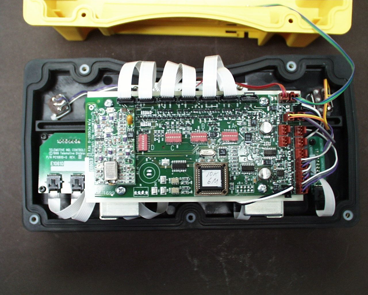
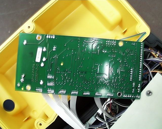
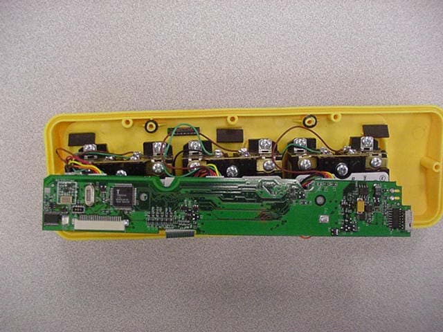
Exhibit B - Technical Description B1.0 Product Description: The Telemotive transmitter Model E13653-JLTX is a joystick version of their remote control for industrial overhead cranes and other material handling equipment. The transmitter operates over the frequency range from 436.0 to 439.8 MHz. The signal is direct frequency modulated and keyed-on in short bursts. The unit transmits when one of the controls is operated. The controls are manually operated and must be held in place to transmit a signal. The transmission ceases when the control is released. A 7.5 Vdc battery is used to power the transmitter. The antenna is an integral part of the printed circuit board. The transmitter operates with its companion receiver FCC ID: GXZE13151 B2.0 Block Diagram: The block diagram is presented in Figure B-1. B3.0 Schematic: The schematic is presented in Figure B-2. B4.0 RF Module Circuit Description: The purpose of the RF Module is to provide an RF output carrier frequency which is direct frequency modulated. This carrier is keyed-on in short burst of data to provide Time Multiplex Sharing (TMS) systems operation. The regulated voltage is maintained at 5 Vdc by means of U1. U1 also provides the on-off control. Oscillator circuit Q1 is crystal controlled by Y1 which operates near 16.2 MHz and depends on the channel frequency trimmer capacitor C1 used to set the oscillator center frequency. The data input level of 0 to +5 peak volts is applied across the varicap diode CR1, which pulls the crystal controlled oscillator above and below the center frequency. This results in a slight FM deviation which is multiplied along with the oscillator center frequency to provide a total 80 kHz deviation bandwidth. Transistor Q2 acts as a tuned frequency tripler resulting in an output near 49 MHz. This circuit is keyed-on by switching transistor Q5 which provides the TMS data operation. Components C11 through C16, L3 and L4 provide a 49 MHz bandpass filter. Transistor Q3 is a second tripler and output amplifier at a frequency of 438 MHz. The harmonics generated by the amplifier are attenuated by the filter made through C28, L7, L8 and L9. The output to the antenna is matched to approximately 50 ohms by the coil tap at the end of L9.
Contact Information
Applicant
Jim Mueller
Fax: 630-582-1217
Test Firm
Elite Electronic Engineering Co.Daniel Crowder
Technical Specifications
| # | Rule Parts | Frequency Range | Power Output |
|---|---|---|---|
| 1 | 15C | 436 MHz - 439.8 MHz | - |
Other Applications from Telemotive Industrial Controls
GXZE10738
Nov 10, 2003Remote Control Transmitter
Equipment Class
DSC - Part 15 Security/Remote Control Transmitter
GXZE10647B
Aug 14, 2002Remote Control Transmitter
Equipment Class
DSC - Part 15 Security/Remote Control Transmitter
GXZE10647
Oct 25, 2001Remote Control Transmitter
Equipment Class
DSC - Part 15 Security/Remote Control Transmitter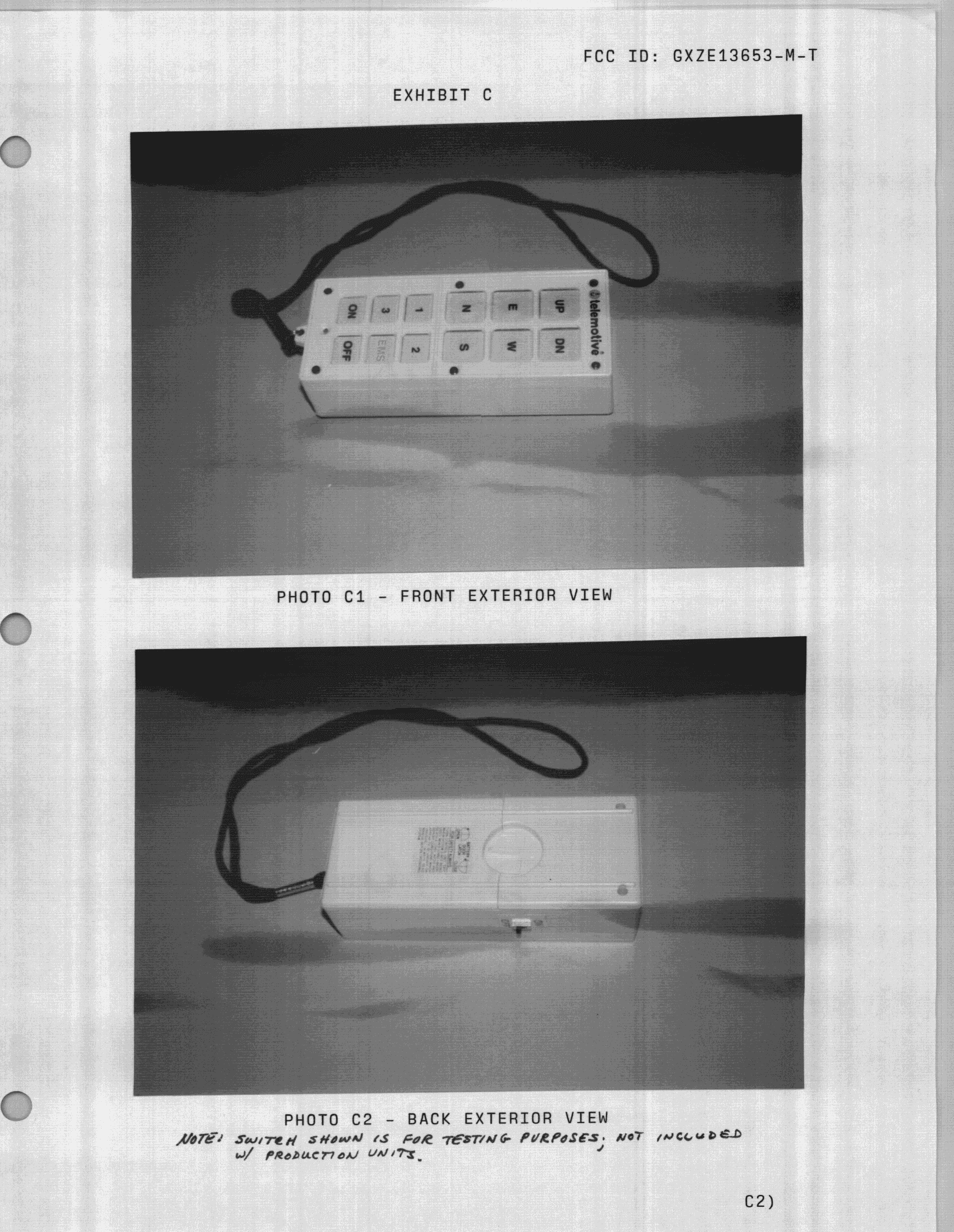
GXZE13653-M-T
Nov 29, 1998R/C Crane Transmitter
Equipment Class
DSC - Part 15 Security/Remote Control Transmitter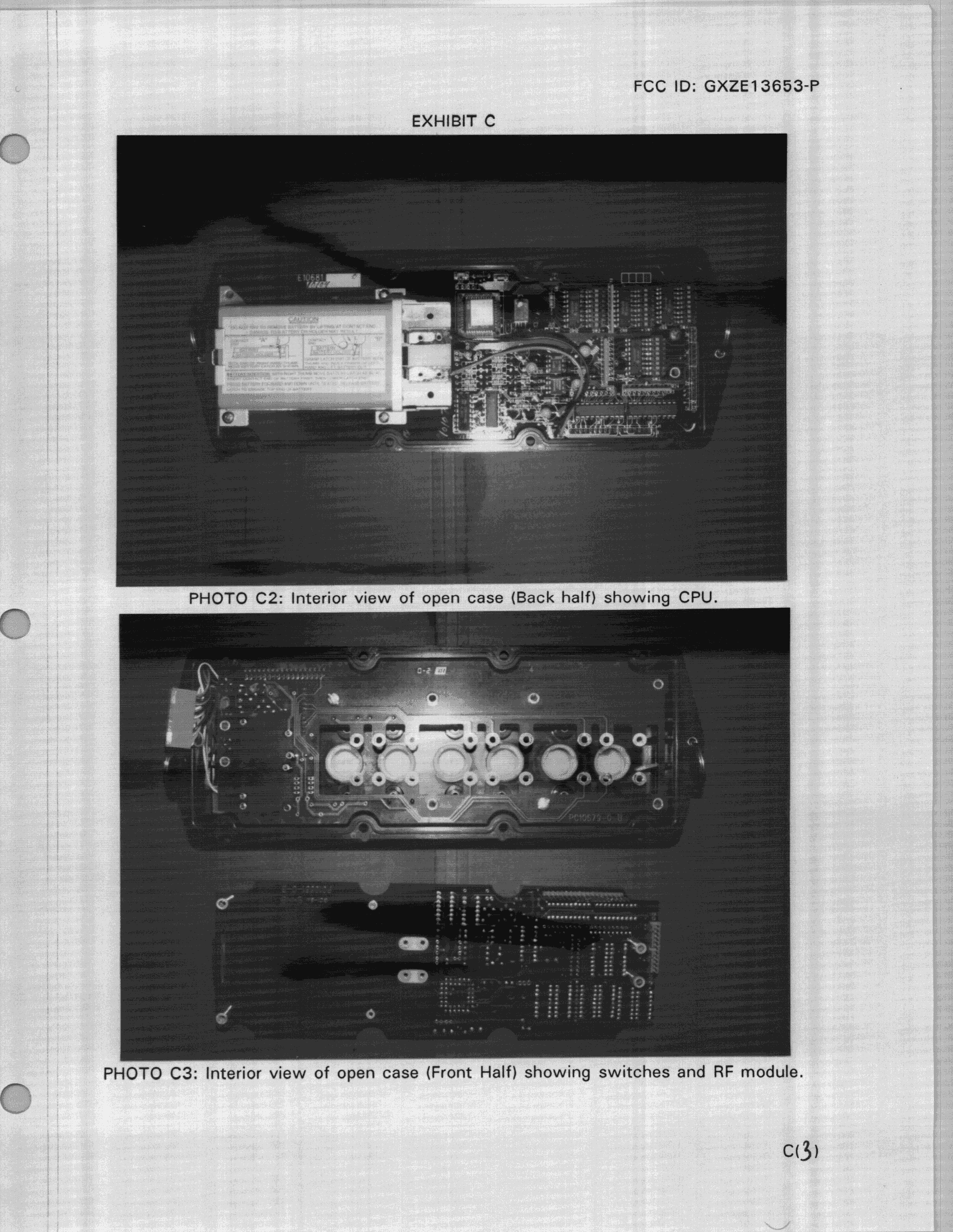
GXZE13653-P
Nov 03, 1998R/C Crane Transmitter
Equipment Class
DSC - Part 15 Security/Remote Control Transmitter