GXZE10647BRemote Control Transmitter
Telemotive Industrial Controls
Click to zoom
Application Details
- Equipment Class
- DSC - Part 15 Security/Remote Control Transmitter
- Date of Grant
- Aug 14, 2002
- Application Purpose
- Original Equipment
- Date of Application
- Aug 14, 2002
- Equipment Note
- Remote Control Transmitter
- Frequency Range
- 433.10000000 - 450.00000000
- Country
- United States
Documents & Files
Document Text
Text extracted from the exhibit documents filed with the FCC. Open a document above to read the original.
Users Manual
TCTX12/TR12-0Rev. F I I N N S S T T A A L L L L A A T T I I O O N N A A N N D D U U S S E E R R S S M M A A N N U U A A L L TELEMOTIVE telePilot TM SERIES TR12 & TX12M-1, -2 R R A A D D I I O O C C O O N N T T R R O O L L S S Y Y S S T T E E M M telemotive ® Industrial Controls 175 Wall Street Glendale Heights, IL 60139-1985 Phone: 630-582-1111, Toll Free: 888-687-4400 Website: http://www.telemotive.com/ tele Pilot Programming is found on page 62. This page intentionally left blank. Table of Contents 3 1- Service Infor ma tion............................................................................................................................3 2- Radio Controlled Crane Safety...........................................................................................................4 1. Warnings, Cautions and Notes......................................................................................4 2. Critical Installation Considerations...............................................................................4 3. General..........................................................................................................................5 4. Persons Authorized To Operate Radio Controlled Cranes...........................................5 5. Training Checklist For Crane Operators.......................................................................5 6. Operating Area..............................................................................................................6 7. Transmitter Unit............................................................................................................6 8. Operating The Crane.....................................................................................................6 9. Boarding The Crane......................................................................................................7 10. Crane Maintenance and Repair.....................................................................................7 11. Using The Crane As A Work Platform.........................................................................8 12. Condition Of The Radio Controlled Crane...................................................................8 13. Batteries........................................................................................................................9 3- General System Information.............................................................................................................11 1. General System Information.......................................................................................11 2. TMS Low Power Signaling........................................................................................11 3. Channel Designations.................................................................................................11 4. System Specifications.................................................................................................11 5. Transmitter Unit..........................................................................................................11 6. Receiver Unit..............................................................................................................12 4- Installation Procedure.......................................................................................................................13 1. Pre-Installation Considerations...................................................................................13 2. Receiver Unit Mounting Location Considerations.....................................................13 3. Antenna Mounting Considerations.............................................................................13 4. Li ne Inp ut Co nsiderations...........................................................................................13 5. Wiring Considerations................................................................................................13 6. Receiver Receiver/Equipment Interface Considerations............................................14 7. Receiver Unit Cabinet Mounting................................................................................14 8. Receiver Installation...................................................................................................14 Figure 4-1. Input Power Connections................................................................................15 Figure 4-2A. Receiver Mounting Details Horizontal with Mounting Brackets.................15 Figure 4-2B. Receiver Mounting Details Vertical with Mounting Brackets.....................16 5- Operation..........................................................................................................................................17 Figure 5-1. tele Pilot, Penda nt and Me mbrane Tra ns mitters. ...........................................17 1. Transmitter Buttons....................................................................................................17 2. ON/OFF LED Indicator..............................................................................................18 3. Low Battery Indicator.................................................................................................18 4. Optional 4 th Motor Select Indicator. ..........................................................................18 5. Operation.....................................................................................................................18 6. Additional tele Pilot Transmitter Operational Features..............................................19 7. Batter y Replacement...................................................................................................18 6- Wiring Diagram................................................................................................................................23 1. Wiring Diagrams.....................................................................................…
Text truncated - open the document above for the full version.
Block Diagram
EXHIBIT B telePilot Block Diagram POWER SUPPLY RF SYTHESIZER CPU MEMORY MAPPED IO DEVICE VC TCX ORF SWITCH KEYPAD FM DEVIATION ADJUST SWI TCH LEDsOFF ON TX MASK BIT 10.000MHz 3.6864MHz XTAL IR PORT 3.6864MHz XTAL
External Photos
C3-EXTERNAL FRONT PHOTO C4-EXTERNAL REAR PHOTO
ID Label/Location Info
B
ID Label/Location Info
MODEL # telePilo t SERIAL # FO R S AFET Y ALWAYS TURN UNIT “OFF” WHEN NOT BEING USED. NEVER STAND UNDERNEATH A LOAD. AVOID AND REPORT CONDI- TIONS WHICH APPEAR UNSAFE OR UNUSUAL. ALWAYS READ MANUAL BEFORE OPERATING. FCC ID: GXZE10647B MA D E I N US A . T HIS DEVICE COM PLIES WIT H PART 15 OF THE FCC RULES. OPERA- TION IS SUBJECT TO THE FOLLOWING TWO CONDITIONS: (1) THIS DEVICE M AY NOT CAUSE HARM FUL INTERFERENCE, AND (2) THIS DEVICE M UST ACCEPT ANY INTERFERENCE RECEIVED, INCLUDING INTERFERENCE THAT MAY CAUSE UNDESIRED OPERATION. Actual size
Internal Photos
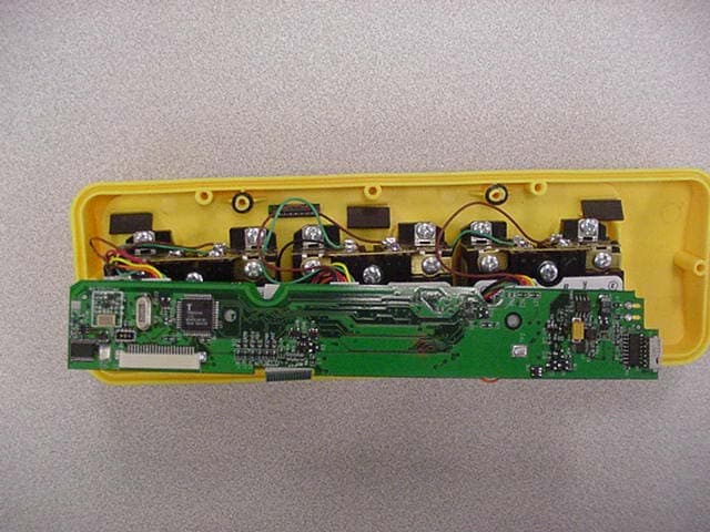
C1-INTERNAL FRONT PHOTO C2-INTERNAL REAR PHOTO
Operational Description
Exhibit B 1 telePilot Operational Description The E10647-0 Radio Control Transmitter Unit is a hand-held unit with built-in antenna. The transmitter is powered by two AA batteries. The transmitter operates in 433 – 450 Mhz UHF frequency band on one of twenty-nine channels. The signal is direct frequency modulated and keyed-on in short bursts. The unit transmits when one of the controls is operated. The controls are manually operated and must be held in place to transmit a signal. The transmission ceases when the control is released. The antenna is a component on the printed circuit board. The unit is microprocessor controlled to provide logic for the synthesizer IC, keypad, LEDs, switches, and timing for Uarts for Data transmission and IR (infra-red) serial programming. The serial data output is fed to an analog switch that is switched between low and high deviation points set by a dual DAC(digital-to-analog converter). The DAC is fed to a VCTCXO running at 10.00MHz. The VCTCXO is fed into the synthesizer IC that produces the 433 – 450 Mhz UHF frequency band. Tune-up procedure: None, auto-tuned. Exhibit B 2 telePilot Block Diagram POWER SUPPLY RF SYTHESIZER CPU MEMORY MAPPED IO DEVICE VC TCX ORF SWITCH KEYPAD FM DEVIATION ADJUST SWI TCH LEDsOFF ON TX MASK BIT 10.000MHz 3.6864MHz XTAL IR PORT 3.6864MHz XTAL Exhibit B 3
Contact Information
Applicant
Jim Mueller
Fax: 630-582-1217
Technical Contact
Elite Electronic Engineering Inc.Daniel E Crowder
[email protected]630 495-9770
1516 Centre Circle · Downers Grove, Illinois · United States
Test Firm
Elite Electronic Engineering Co.Daniel Crowder
Technical Specifications
| # | Rule Parts | Frequency Range | Power Output |
|---|---|---|---|
| 1 | 15.231,15.231 | 433.1 MHz - 450 MHz | - |
Other Applications from Telemotive Industrial Controls
GXZE10738
Nov 10, 2003Remote Control Transmitter
Equipment Class
DSC - Part 15 Security/Remote Control Transmitter
GXZE10647
Oct 25, 2001Remote Control Transmitter
Equipment Class
DSC - Part 15 Security/Remote Control Transmitter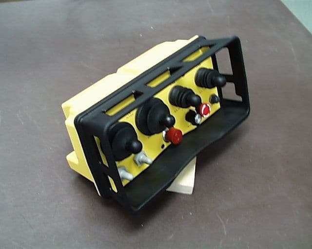
GXZE13653-JLTX
Oct 17, 1999Industrial Crane Remote Control
Equipment Class
DSC - Part 15 Security/Remote Control Transmitter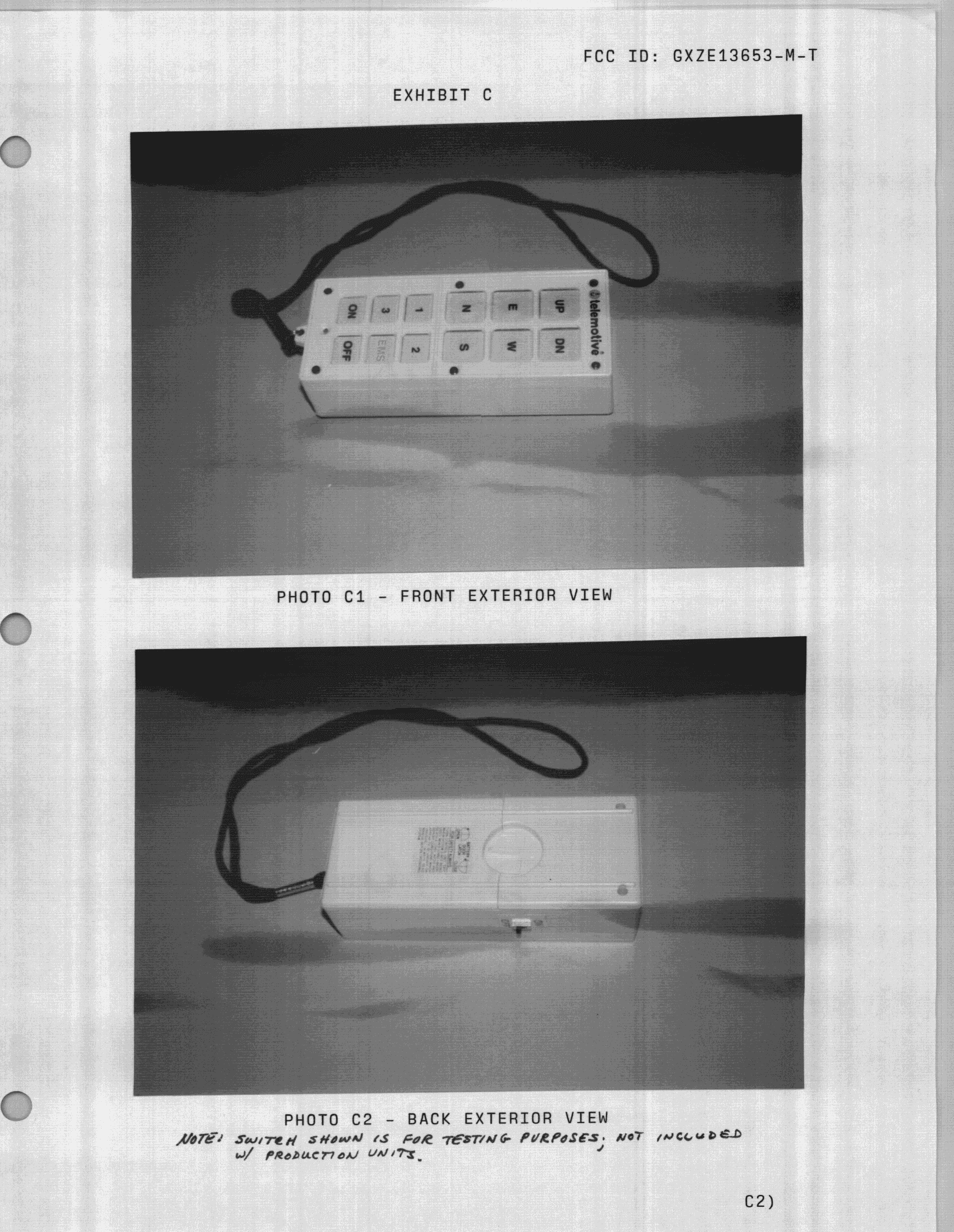
GXZE13653-M-T
Nov 29, 1998R/C Crane Transmitter
Equipment Class
DSC - Part 15 Security/Remote Control Transmitter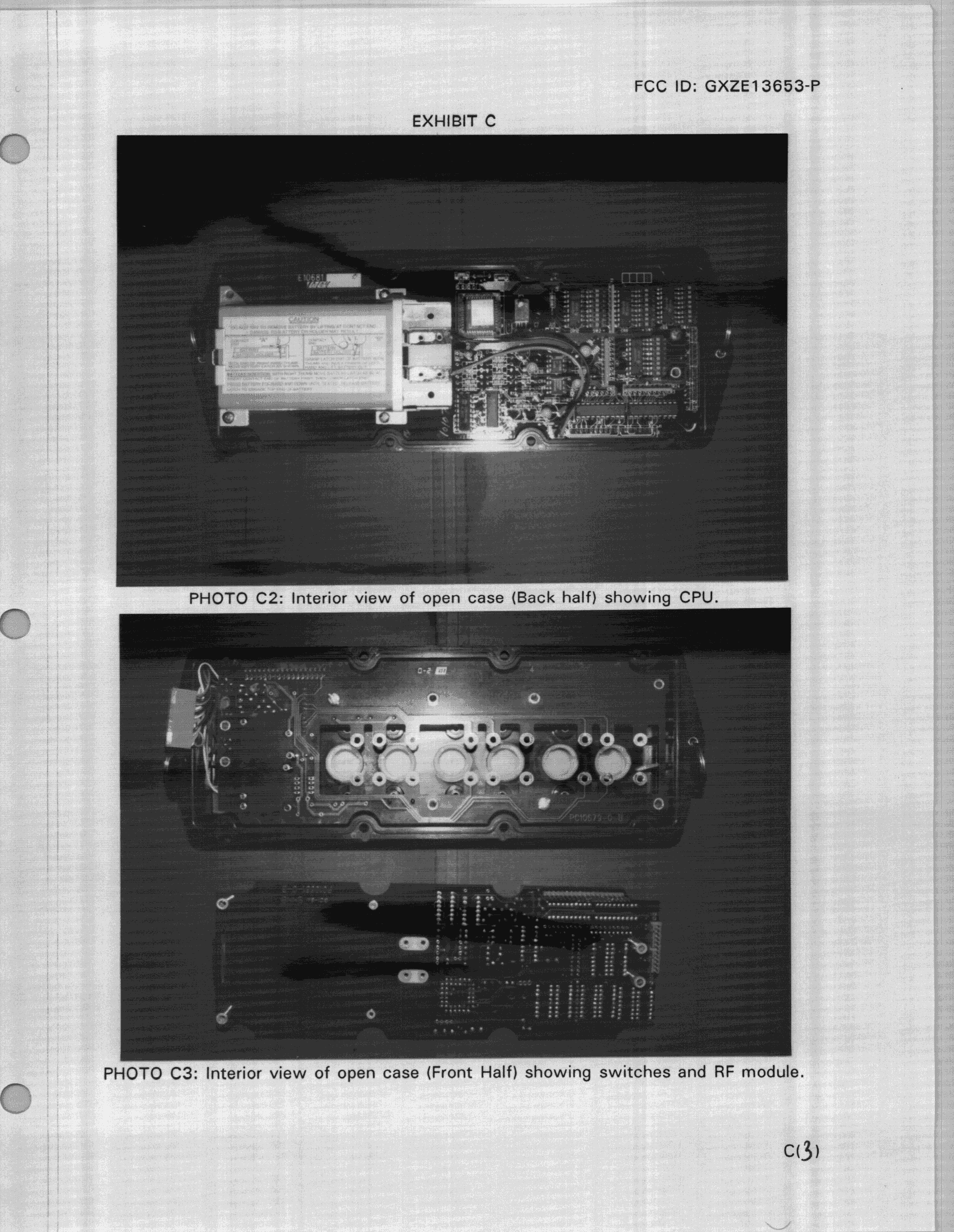
GXZE13653-P
Nov 03, 1998R/C Crane Transmitter
Equipment Class
DSC - Part 15 Security/Remote Control Transmitter