H4JAMP-3-150AMP-3/140-30 & AMP-3/160-30
Zetron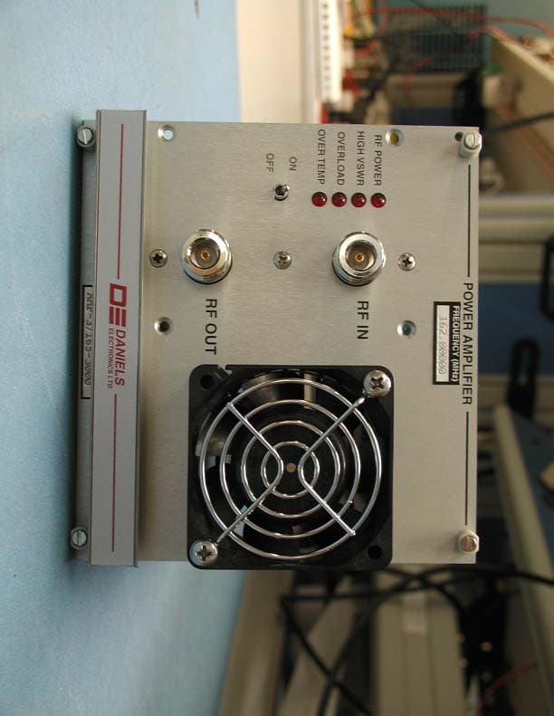
Click to zoom
Application Details
- Equipment Class
- AMP - Amplifier
- Date of Grant
- Dec 11, 2003
- Application Purpose
- Original Equipment
- Date of Application
- Dec 11, 2003
- Equipment Note
- AMP-3/140-30 & AMP-3/160-30
- Frequency Range
- 136.00000000 - 174.00000000
- Company
- Zetron
- Country
- Canada
Documents & Files
Document Text
Text extracted from the exhibit documents filed with the FCC. Open a document above to read the original.
Users Manual
Copyright © 2003 Daniels Electronics Ltd. All rights reserved. No part of this publication may be reproduced, stored in a retrieval system or transmitted in any form or by any means, electronic, mechanical, photocopying, recording or otherwise, without the prior written consent of Daniels Electronics Ltd. DE™ is a registered trademark of Daniels Electronic Ltd. registered in the U.S. Patent and Trademark Offi ce. Document Number: Revision: Revision Date: Daniels Electronics Ltd. Victoria, BC PRINTED IN CANADA VHF 30W POWER AMPLIFIER INSTRUCTION MANUAL AMP-3/150 136-174 MHZ Covers Models: AMP-3/140-30 AMP-3/160-30 IM71-AMP3150-30 1-1-0 Nov 2003 VHF 30W Power Amplifi er Instruction Manual IM71-AMP3150-30 ii This document has been produced, verifi ed and controlled in accordance with Daniels Electronics’ Quality Management System requirements. Please report any errors or problems to Daniels Electronics’ Customer Service Department. The user’s authority to operate this equipment could be revoked through any changes or modifi cations not expressly approved by Daniels Electronics Ltd. The design of this equipment is subject to change due to continuous development. This equipment may incorporate minor changes in detail from the information contained in this manual. DOCUMENT CONTROL NOTE VHF 30W Power Amplifi er Instruction Manual IM71-AMP3150-30 iii RF Exposure Warning Exposure to radio frequency (RF) energy has been identifi ed as a potential environmental factor that must be considered before a radio transmitter can be authorized or licensed. The FCC has therefore developed maximum permissible exposure (MPE) limits for fi eld strength and power density, listed in FCC 47 CFR § 1.1310. The FCC has furthermore determined that determination of compliance with these exposure limits, and preparation of an Environmental Assessment (EA) if the limits are exceeded, is necessary only for facilities, operations and transmitters that fall into certain risk categories, listed in FCC 47 CFR § 1.1307 (b), Table 1. All other facilities, operations and transmitters are categorically excluded from making such studies or preparing an EA, except as indicated in FCC 47 CFR §§ 1.1307 (c) and (d). Revised FCC OET Bulletin 65 (Edition 97-01) provides assistance in determining whether a proposed or existing transmitting facility, operation or device complies with RF exposure limits. In accordance with OET Bulletin 65 and FCC 47 CFR § 1.1307 (b), this Daniels Electronics Ltd. transmitter is categorically excluded from routine evaluation or preparing an EA for RF emissions and this exclusion is suffi cient basis for assuming compliance with FCC MPE limits. This exclusion is subject to the limits specifi ed in FCC 47 CFR §§ 1.1307 (b) and 1.1310. Daniels Electronics Ltd. has no reason to believe that this excluded transmitter encompasses exceptional characteristics that could cause non-compliance. Notes: • The FCC’s exposure guidelines constitute exposure limits, not emission limits. They are relevant to locations that are accessible to workers or members of the public. Such access can be restricted or controlled by appropriate means (i.e. fences, warning signs, etc.). • The FCC’s limits apply cumulatively to all sources of RF emissions affecting a given site. Sites exceeding these limits are subject to an EA and must provide test reports indicating compliance. RF Safety Guidelines and Information Base and Repeater radio transmitters are designed to generate and radiate RF energy by means of an external antenna, typically mounted at a signifi cant height above ground to provide adequate signal coverage. The following antenna installation guidelines are extracted from Appendix A to OET Bulletin 65 and must be adhered to in order to ensure RF exposure compliance: Non-building-mounted Antennas: Height above ground level to lowest point of antenna ≥ 10 m or Power ≤ 1000W ERP (1640 W EIRP) Building-mounted Antennas: Power ≤ 1000 W ERP (1640 W EIRP) The following RF Safety Guidelines should be observed when working in or around transmitter sites: • Do not work on or around any transmitting antenna while RF power is applied. • Before working on an antenna, disable the appropriate transmitter and ensure a “DO NOT USE” or similar sign is placed on or near the PTT or key-up control. • Assume all antennas are active unless specifi cally indicated otherwise. • Never operate a transmitter with the cover removed. • Ensure all personnel entering a transmitter site have electromagnetic energy awareness training. For more information on RF energy exposure and compliance, please refer to the following: 1) FCC Code of Regulations; 47 CFR §§ 1.1307 and 1.1310. 2) FCC OET Bulletin 65, Edition 97-01, “Evaluating Compliance with FCC Guidelines for Human Exposure to Radiofrequency Electromagnetic Fields”. 3) http://www.fcc.gov/oet/rfsafety / VHF 30W Power Amplifi er Instruction Manual IM71-AMP3150-30 v Contents General Information ...............................................................1 Introduction ................................................................................................1 Performance Specifi cations .......................................................................2 Physical Specifi cations ..............................................................................3 Theory of Operation ...............................................................5 General ......................................................................................................5 Amplifi er PCB Circuitry ..............................................................................5 Control PCB Circuitry .................................................................................6 Alignment & Installation .........................................................9 Recommended Test Equipment .................................................................9 Amplifi er Board Alignment.......................................…
Text truncated - open the document above for the full version.
Block Diagram
VHF 30W Power Amplifi er Instruction Manual IM71-AMP3150-30 Illustrations and Schematics 14 VHF 30W POWER AMPLIFIER BLOCK DIAGRAM FRONT PANEL CONTROL BOARD AMPLIFIER BOARD Fan -6dB ATT. Driver Controller / Circuit Breaker RF AmpDir. Coupler LPF Thrm. Sensor Gate & Volt. Control Fwd Pwr Sampler RF Detector ON OFF RF POWER HIGH VSWR OVERLOAD OVER TEMP RF IN RF OUT REMOTE RF POWER REMOTE HIGH VSWR +9.5VDC +13.8VDC (Fan active only when temperature over +40 O C) VHF 30W POWER AMPLIFIER – BLOCK DIAGRAM REAR CONNECTOR
Cover Letter(s)
DANIELS ELECTRONICS LTD. TM Telephone: (250) 382-8268 43 ERIE ST., VICTORIA, BC FAX: (250) 382-6139 CANADA, V8V 1P8 Website: www.danelec.com RADIO COMMUNICATION MANUFACTURER November 12, 2003 Curtis-Straus LLC 527 Great Road Littleton, MA 01460 Attention : Barry Quinlan Certification of Single Channel Power Amplifier Family Daniels Electronics Ltd. is seeking certification for its AMP-3/150 Family of VHF FM 30 Watt Single Channel RF Power Amplifiers. This family covers the LMR VHF frequency band of 136 MHz to 174 MHz in two models: 1. AMP-3/140-30 VHF 30 Watt Power Amplifier (136 - 150 MHz sub-band); and 2. AMP-3/160-30 VHF 30 Watt Power Amplifier (150 - 174 MHz sub-band); The two models within this family correspond to the sub-bands of the LMR VHF frequency band in the USA and Canada. The two models are electrically identical, utilizing identical controller and RF sub- modules. The models differ from each other by a limited number of frequency-select discrete components that optimize RF output coupling for the particular sub-band of interest. A summary of these frequency-select components follows: Model Frequency- select Component AMP-3/140-30 (136 - 150MHz) AMP-3/160-30 (150 - 174MHz) C6 150pF 120pF C7 150pF 120pF C8 150pF 68pF C9 100pF 68pF C11 10pF Not Installed C48 5.6nF Not Installed L5 4 Turns 3 Turns L6 4 Turns 3 Turns L7 4 Turns 3 Turns L8 4 Turns 3 Turns R33 221R Not Installed Page 2 of 2 For reasons of economy, test report results for the AMP-3/160-30 model have been chosen as representative of the AMP-3/150 Family of VHF FM Power Amplifiers, since electrical performance of both models is identical. Dated this 12 th day of November, 2003 By: Ron Backlund, MEng Manager, Projects & Regulatory Strategy Daniels Electronics Ltd. 43 Erie Street Victoria, BC, Canada V8V 1P8 Phone: (250) 382-8268 or (800) 664-4066 Fax: (250) 382-6139 or (877) 750-0004 E-mail: [email protected]
Cover Letter(s)
DANIELS ELECTRONICS LTD. TM Telephone: (250) 382-8268 43 ERIE ST., VICTORIA, BC Fax: (250) 382-6139 CANADA, V8V 1P8 E-Mail: [email protected] Website: www.danelec.com RADIO COMMUNICATION MANUFACTURER FCC ID: H4JAMP-3-150 November 12, 2003 Curtis-Straus LLC 527 Great Road Littleton, MA 01460 Attention : Barry Quinlan REQUEST FOR CONFIDENTIALITY Reference : FCC ID: H4JAMP-3-150 In accordance with 47 CFR§ 0.457(d)(ii) and pursuant to 47 CFR§ 0.459(a), Daniels Electronics Ltd requests that the following exhibits submitted in support of this application for equipment authorization not be made routinely available to the public: Exhibits : Operational Description Schematics and Illustrations Parts Lists The above-mentioned exhibits contain trade secret information which is not made routinely available to the public or to our competitors. Disclosure of this information could result in an unfair advantage to our competitors. This information should be treated as confidential for the duration of effectiveness of the Grant of Authorization. Ron Backlund, M.Eng. Manager, Projects & Regulatory Strategy Daniels Electronics Ltd. 43 Erie Street Victoria, BC V8V 1P8 Phone: (250) 382-8268 Fax: (250) 382-6139 E-Mail: [email protected] Web: www.danelec.com
ID Label/Location Info
FRONT PANEL BOTTOM TOP LEFT SIDE COVER EQUIPMENT ID LABEL FORMAT & LOCATION AMP-3/150 30 Watt VHF Power Amplifier Family VR-3H045-S 10001 9/03 N/A (DoC) 142A-VR3X0X5S MODEL: IC: FCC ID: VICTORIA , B.C. CANADA SERIAL #: DATE: AMP-3/160-30 H4JAMP-3-150 10001 10/03 142A-AMP3150 DANIELS TM ELECTRONICS LTD
Parts List/Tune Up Info
VHF 30W Power Amplifi er Instruction Manual IM71-AMP3150-30 21 PARTS LIST AMPLIFIER BOARD ELECTRICAL PARTS LIST Ref Desig Description Part No C1 CAP., SM,330pF PORCEL.,5%,200V 1036-2B2331J2 C2 CAP., SM,43pF PORCEL.,5%,500V 1036-1B2430J5 C4 CAP., SM,150pF PORCEL.,5%,300V 1036-2B2151J3 C5 CAP., SM,220pF PORCEL.,5%,200V 1036-2B2221J2 C6 CAP., SM,120pF PORCEL.,5%,300V 1036-2B2121J3 C7 CAP., SM,120pF PORCEL.,5%,300V 1036-2B2121J3 C8 CAP., SM,68pF PORCEL., 5%,500V 1036-1B2680J5 C9 CAP., SM,68pF PORCEL., 5%,500V 1036-1B2680J5 C10 CAP., SM,39pF PORCEL.,+-5%500V 1036-1B2390J5 C12 CAP.,TRIM. 1-20pF, STAND. >12T 1082-A1R0020K C13 CAP., SM,330pF PORCEL.,5%,200V 1036-2B2331J2 C14 CAP., SM,20pF PORCEL., 5%,500V 1036-1B2200J5 C15 CAP., SM,39pF PORCEL.,+-5%500V 1036-1B2390J5 C16 CAP., SM,39pF PORCEL.,+-5%500V 1036-1B2390J5 C17 CAP., SM,39pF PORCEL.,+-5%500V 1036-1B2390J5 C18 CAP., SM,20pF PORCEL., 5%,500V 1036-1B2200J5 C19 CAP., SM, 2.2pF CER., 0805,C0G 1008-0A229J1G C20 CAP., SM, 100pF CER., 0805,C0G 1008-2A101J1G C21 CAP., SM,100nF CER,0805,X7R,50 1008-5A104K5R C22 CAP., SM, 330pF CER., 1206,C0G 1008-2B331J1G C23 CAP., SM, 680pF CER., 1206,C0G 1008-2B681J1G C24 CAP., SM, 1nF CER,0805,X7R,50V 1008-3A102K5R C25 CAP., SM,10nF CER,0805,X7R,50V 1008-4A103K5R C26 CAP., SM,100nF CER,0805,X7R,50 1008-5A104K5R C27 CAP., SM, 330pF CER., 0805,C0G 1008-2A331J1G C28 CAP., SM,330pF PORCEL.,5%,200V 1036-2B2331J2 C29 CAP., SM, 22uF TANT., 20%, 20V 1055-6D226M20 C30 CAP., SM, 22uF TANT., 20%, 20V 1055-6D226M20 C31 CAP., SM, 1nF CER., 1206, C0G 1008-3B102K1G C32 CAP., SM, 1.0uF TANT., 20%,16V 1055-5A105M16 C33 CAP., SM, 330pF CER., 0805,C0G 1008-2A331J1G C34 CAP.,SM,330nF CER,0805,X7R,25V 1008-5A334M3R C35 CAP., SM, 330pF CER., 0805,C0G 1008-2A331J1G C36 CAP., SM, 330pF CER., 0805,C0G 1008-2A331J1G C37 CAP., SM, 1nF CER,0805,X7R,50V 1008-3A102K5R C38 CAP.,SM,1.0uF CER,1206,X7R,25V 1008-6B105K3R VHF 30W Power Amplifi er Instruction Manual IM71-AMP3150-30 Parts List 22 Ref Desig Description Part No C39 CAP., SM, 330pF CER., 0805,C0G 1008-2A331J1G C40 CAP., SM, 1nF CER,0805,X7R,50V 1008-3A102K5R C41 CAP., SM,3.0pF PORCEL.,+-.25pF 1036-0B2309C5 C42 CAP., SM,10nF CER,0805,X7R,50V 1008-4A103K5R C43 CAP., SM, 220pF CER., 0805,C0G 1008-2A221J1G C44 CAP., SM, 220pF CER., 0805,C0G 1008-2A221J1G C45 CAP., SM, 1.0uF TANT., 20%,35V 1055-5B105M35 C46 CAP., SM, 1nF CER,0805,X7R,50V 1008-3A102K5R C47 CAP., SM, 330pF CER., 0805,C0G 1008-2A331J1G D1 DIODE, MMBD701,HOT CARR.,SOT23 2105-MMBD7010 D2 DIODE, MMBD701,HOT CARR.,SOT23 2105-MMBD7010 D3 DIODE/ZEN,BZV55-C6V2,6.2V,SD80 2102-BZV556V2 D4 DIODE, MMBD701,HOT CARR.,SOT23 2105-MMBD7010 D5 DIODE, MMBD701,HOT CARR.,SOT23 2105-MMBD7010 D6 DIODE, MMBD701,HOT CARR.,SOT23 2105-MMBD7010 J1 CABLE, TYPE N JACK-OPEN, 9.7cm 7910-NJ603009 J2 CABLE, TYPE N JACK-OPEN, 7.7cm 7910-NJ602007 J3 SOCKET,SM,.2”,4CCT,LK CLIP,15A 5023-S004SLCT J4 SOCKET, 4 POS, DBL ROW/VERT,LC 5010-SS04DV1S L1 INDUCTOR/AIR CORE,SM,17.5nH,6T 1254-1B17N01G L10 CHOKE/RF, FERRITE, 2.5 TURNS 1211-43061025 L2 INDUCTOR/AIR CORE,SM,5nH,2TURN 1254-0A05N01G L3 COIL, 1 TURN, 18AWG,6.40 mm ID 1220-1T001822 L4 COIL, 1 TURN, 18AWG, 6.40mm ID 1220-1T001818 L5 COIL, 3 TURNS,18AWG,6.35 mm ID 1220-3T001823 L6 COIL, 3 TURNS,18AWG,6.35 mm ID 1220-3T001823 L7 COIL, 3 TURNS,18AWG,6.35 mm ID 1220-3T001823 L8 COIL, 3 TURNS,18AWG,6.35 mm ID 1220-3T001823 L9 COIL, 4 TURNS,18AWG, 4.80mm ID 1220-4T001816 PCB PCB, AMP, VHF/FM 30 WATT AMP 4321-80011103 Q1 MOSFET,RF,MRF1535T1,35W,TO-272 2043-MRF1535T Q2 TRANSISTOR, BC817-25,NPN,SOT23 2120-BC817025 Q3 MOSFET, VP0610T,P CHAN.,SOT-23 2142-VP0610T0 Q4 MOSFET, 2N7002LT1,N-CHAN,SOT23 2142-2N7002L0 R1 RES., SM, 301R 2512, 1%,100ppm 1150-2E3010FP R2 RES., SM, 301R 2512, 1%,100ppm 1150-2E3010FP R3 RES., SM, 75R0 2512, 1%,100ppm 1150-1E75R0FP R4 RES., SM, 75R0 2512, 1%,100ppm 1150-1E75R0FP R5 RES., SM, 150R 2512, 1%,100ppm 1150-2E1500FP R6 RES., SM, 49R9 0805, 1%,100ppm 1150-1A49R9FP R7 RES., SM, 12R1 1206, 1%,100ppm 1150-1B12R1FP R8 RES., SM, 12R1 1206, 1%,100ppm 1150-1B12R1FP R9 RES., SM, 49K9 0805, 1%,100ppm 1150-4A4992FP R10 RES., SM, 100K 0805, 1%,100ppm 1150-5A1003FP R11 RES., SM, 2K21 0805, 1%,100ppm 1150-3A2211FP R12 RES., SM, 475R 0805, 1%,100ppm 1150-2A4750FP R13 RES., SM, 2K00 0805, 1%,100ppm 1150-3A2001FP R14 RES., SM, 3K01 0805, 1%,100ppm 1150-3A3011FP R15 RES., SM, 18K2 0805, 1%,100ppm 1150-4A1822FP R17 RES., SM, 11K3 0805, 1%,100ppm 1150-4A1132FP R18 RES., SM, 100K 0805, 1%,100ppm 1150-5A1003FP R19 RES., SM, 10K0 0805, 1%,100ppm 1150-4A1002FP R20 RES., SM, 10K0 0805, 1%,100ppm 1150-4A1002FP R21 RES., SM, 10K0 0805, 1%,100ppm 1150-4A1002FP VHF 30W Power Amplifi er Instruction Manual IM71-AMP3150-30 Parts List 23 Ref Desig Description Part No R22 RES., SM, 1K00 0805, 1%,100ppm 1150-3A1001FP R23 RES., SM, 10K0 0805, 1%,100ppm 1150-4A1002FP R24 RES., SM, 18K2 0805, 1%,100ppm 1150-4A1822FP R25 RES., SM, 100K 0805, 1%,100ppm 1150-5A1003FP R26 RES., SM, 18K2 0805, 1%,100ppm 1150-4A1822FP R27 RES., SM, 10K0 0805, 1%,100ppm 1150-4A1002FP R28 RES., SM, 49R9 1206, 1%,100ppm 1150-1B49R9FP R29 RES., SM, 49R9 1206, 1%,100ppm 1150-1B49R9FP R30 RES., SM, 3K01 0805, 1%,100ppm 1150-3A3011FP R31 RES., SM, 3K01 0805, 1%,100ppm 1150-3A3011FP R32 RES., SM, 100K 0805, 1%,100ppm 1150-5A1003FP RV1 POT., SM, 5K0, 12T, TOP ADJUST 1172-M20502W5 U1 IC,LM56BI,THERMOSTAT,D O/P,S08 2318-LM560N08 U2 IC,INA132, DIFFERENCE AMP,SO-8 2301-INA132N8 U3 IC, LP2951,PROG. VOLT REG,SO-8 2305-29510N08 VHF 30W Power Amplifi er Instruction Manual IM71-AMP3150-30 Parts List 24 Ref Desig Description Part No CONTROL BOARD ELECTRICAL PARTS LIST C1 CAP., SM,100nF CER,0805,X7R,50 1008-5A104K5R C2 CAP., SM,100nF CER,0805,X7R,50 1008-5A104K5R C3 CAP., SM, 330pF CER., 0805,C0G 1008-2A331J1G C4 CAP., SM,100nF CER,0805,X7R,50 1008-5A104K5R C5 CAP.,SM,330nF CER,0805,X7R,25V 1008-5A334M3R C6 CAP., SM, 330pF CER., 0805,C0G 1008-2A331J1G C7 CAP., SM,100nF CER,0805,X7R,50 1008-5A104K5R C8 CAP., SM, 330pF CER., 0805,C0G 1008-2A331J1G C9 CAP., SM,100nF CER,0805,X7R…
Text truncated - open the document above for the full version.
Parts List/Tune Up Info
VHF 30W Power Amplifi er Instruction Manual IM71-AMP3150-30 9 ALIGNMENT & INSTALLATION RECOMMENDED TEST EQUIPMENT Daniels Subrack SR-39-1 with System Monitor Daniels Extender Card Kit EC-48RK Power Supply Regulated 13.8VDC @ 10A Current Meter 5.0A DC Voltmeter RF Coupler (eg. Bird 4275) Wattmeter (eg. Bird 4421) VSWR Meter (eg. Bird 4421) Dummy Loads 50 Ohm, 3:1 (50W) Spectrum Analyzer (eg. IFR 2975) VHF 30W Power Amplifi er Instruction Manual IM71-AMP3150-30 Alignment & Installation 10 AMPLIFIER BOARD ALIGNMENT Refer to the VHF 30W Power Amplifi er Board Component Layout Diagram for the location of the adjustment capacitors, potentiometers, air- core coils and test points. This procedure assumes the use of a single subrack with an EC-48RK extender card kit for both the exciter and the power amplifi er such that their internal adjustment points are easily accessible. Step 1: Remove the top extrusion cover from the transmitter exciter. Set the exciter frequency to either 143MHz or 162MHz depending upon whether you are tuning a lowband or highband unit, respectively. Step 2: Install one of the extender cards in the designated location for the exciter within the subrack. Connect the exciter to this extender card using the gray connector cable provided with the extender card kit. Step 3: Refer to the ‘VHF 30W Power Amplifi er Exploded View’ on page 15 for help on the following procedures. Remove the power amplifi er 14HP case. Next, unplug the cooling fan from the control board and remove the front panel. Using suitable male connectors or a test jig, apply the following signals directly to the amplifi er board: • 13.8V : J3 - Pin1, Pin 2 Note: Ensure an ammeter is connected in series with this line. • Gnd : J3 - Pin 3, Pin 4 • 9.5V : J4 - Pin 4 • Gnd : J4 - Pin 8 (RF Input Sample) Step 4: While monitoring the current on the 13.8V line and without an RF input to the power amplifi er, slowly adjust the potentiometer RV1 until the current reads 230mA. As a check, measure the voltage at TP1. It should read between 2.5V and 3.0V. Step 5: Now connect the output of the exciter to the input of the power amplifi er. Connect the output of the power amplifi er through a suitable RF coupler then through a power meter and fi nally terminate the output with a 50 Ohm load. The low power output from the RF coupler should be connected to the input of a spectrum analyzer. The spectrum analyzer should have an output tracking generator capable of putting out at least a +6dBm signal. This output should be connected to the input of the exciter amplifi er which is fi rst disconnected from the exciter’s local oscillator. Step 6: Before enabling the tracking generator, the output power of the exciter amplifi er should be disabled by turning its potentiometer fully counterclockwise (~12 Turns). Now turn the exciter on by setting the front panel switch to ‘Key Tx’. Set the center frequency on the spectrum analyzer to the same frequency the exciter was set to in Step 1. Next, set the span to 0 Hz and enable the tracking generator with a +6dBm output. Step 7: While monitoring the output on the power meter and ensuring 13.8V on the PA amplifi er board, slowly increase the exciter amplifi er output until 30W is reached. Increase the span on the spectrum analyzer to 20MHz. Next, remove the cover on the low-pass fi lter shield (10601-01) on the amplifi er PCB to allow access to the air-core inductors, L5 to L8. Monitoring the output response on the spectrum analyzer, tune these inductors by altering the spacing between the windings with a plastic adjusting tool for maximum fl atness and gain across the desired band (136 - 150MHz for lowband, 150 - 174MHz for highband). Then capacitor C12 should be adjusted for maximum fl atness and gain also. Step 8: Set the span on the spectrum analyzer to 0 Hz and check that output VSWR is below 1.20 on the band edges and the center frequency of the band. Step 9: As a fi nal check, replace the low-pass fi lter shield and using the spectrum analyzer again, search the band (either 136 - 150MHz or 150 - 174 MHz) for any unwanted spurious emissions. VHF 30W Power Amplifi er Instruction Manual IM71-AMP3150-30 Alignment & Installation 11 CONTROL BOARD ALIGNMENT Refer to the VHF 30W Power Amplifi er Control Board Component Layout Diagram for the location of the adjustment potentiometers and test points. This procedure assumes the use of 1/2 wavelength RF output cables between all pieces of test equipment after the PA output for accurate power readings during mismatched load conditions. Step 1: Once the amplifi er board alignment is complete, the exciter can be turned off and its amplifi er re-connected to the local oscillator. Next, the male connectors or test jig can be removed from the amplifi er board and the control board along with the front panel can be re-connected to the power amplifi er. The power amplifi er can then be connected via the gray cable to the second extender card which should be installed in the designated location within the subrack for the power amplifi er. Step 2: With the exciter’s output still connected to the input of the power amplifi er and the output of the power amplifi er still connected through an RF coupler into a wattmeter and 50 Ohm load, set the transmitter to the desired frequency. Next, adjust the output power of the exciter such that the PA output is 10W. Then adjust potentiometer RV1 until LED1, or the ‘RF POWER’ indicator, just turns on. This threshold may be adjusted to any RF output power level between 10W and 30W. Step 3: Set the exciter output power such that the output power from the PA is equal to that under normal operating conditions. Replace the 50 Ohm load with a suitably rated 3:1 mismatched load. Adjust potentiometer RV2 until LED2, or the ‘HIGH VSWR’ indicator, just turns on. Step 4: As a check, terminate the power amplifi er once again with a 50 Ohm load and ensure that LED2 is now off. If it is not off, adjust RV2 until LED2 just turns of…
Text truncated - open the document above for the full version.
RF Exposure Info
VHF 30W Power Amplifi er Instruction Manual IM71-AMP3150-30 iii RF Exposure Warning Exposure to radio frequency (RF) energy has been identifi ed as a potential environmental factor that must be considered before a radio transmitter can be authorized or licensed. The FCC has therefore developed maximum permissible exposure (MPE) limits for fi eld strength and power density, listed in FCC 47 CFR § 1.1310. The FCC has furthermore determined that determination of compliance with these exposure limits, and preparation of an Environmental Assessment (EA) if the limits are exceeded, is necessary only for facilities, operations and transmitters that fall into certain risk categories, listed in FCC 47 CFR § 1.1307 (b), Table 1. All other facilities, operations and transmitters are categorically excluded from making such studies or preparing an EA, except as indicated in FCC 47 CFR §§ 1.1307 (c) and (d). Revised FCC OET Bulletin 65 (Edition 97-01) provides assistance in determining whether a proposed or existing transmitting facility, operation or device complies with RF exposure limits. In accordance with OET Bulletin 65 and FCC 47 CFR § 1.1307 (b), this Daniels Electronics Ltd. transmitter is categorically excluded from routine evaluation or preparing an EA for RF emissions and this exclusion is suffi cient basis for assuming compliance with FCC MPE limits. This exclusion is subject to the limits specifi ed in FCC 47 CFR §§ 1.1307 (b) and 1.1310. Daniels Electronics Ltd. has no reason to believe that this excluded transmitter encompasses exceptional characteristics that could cause non-compliance. Notes: • The FCC’s exposure guidelines constitute exposure limits, not emission limits. They are relevant to locations that are accessible to workers or members of the public. Such access can be restricted or controlled by appropriate means (i.e. fences, warning signs, etc.). • The FCC’s limits apply cumulatively to all sources of RF emissions affecting a given site. Sites exceeding these limits are subject to an EA and must provide test reports indicating compliance. RF Safety Guidelines and Information Base and Repeater radio transmitters are designed to generate and radiate RF energy by means of an external antenna, typically mounted at a signifi cant height above ground to provide adequate signal coverage. The following antenna installation guidelines are extracted from Appendix A to OET Bulletin 65 and must be adhered to in order to ensure RF exposure compliance: Non-building-mounted Antennas: Height above ground level to lowest point of antenna ≥ 10 m or Power ≤ 1000W ERP (1640 W EIRP) Building-mounted Antennas: Power ≤ 1000 W ERP (1640 W EIRP) The following RF Safety Guidelines should be observed when working in or around transmitter sites: • Do not work on or around any transmitting antenna while RF power is applied. • Before working on an antenna, disable the appropriate transmitter and ensure a “DO NOT USE” or similar sign is placed on or near the PTT or key-up control. • Assume all antennas are active unless specifi cally indicated otherwise. • Never operate a transmitter with the cover removed. • Ensure all personnel entering a transmitter site have electromagnetic energy awareness training. For more information on RF energy exposure and compliance, please refer to the following: 1) FCC Code of Regulations; 47 CFR §§ 1.1307 and 1.1310. 2) FCC OET Bulletin 65, Edition 97-01, “Evaluating Compliance with FCC Guidelines for Human Exposure to Radiofrequency Electromagnetic Fields”. 3) http://www.fcc.gov/oet/rfsafety /
RF Exposure Info
Prediction of MPE limit at a given distance This prediction is based on the RF Safety Installation Guideline of 1640W E.I.R.P Equation from page 18 of OET Bulletin 65, Edition 97-01where: S = power density P = power input to the antennaG = power gain of the antenna in the direction of interest relative to an isotropic radiatorR = distance to the center of radiation of the antenna Maximum peak output power at antenna input terminal: 45.00 (dBm) Maximum peak output power at antenna input terminal: 31622.7766 (mW) Antenna gain(typical): 17 (dBi) Maximum antenna gain: 50.11872336 (numeric) Prediction distance: 1000 (cm) Prediction frequency: 136-174 (MHz) MPE limit for uncontrolled exposure at prediction frequency: 0.2 (mW/cm^2) Power density at prediction frequency: 0.126122 (mW/cm^2) Maximum allowable antenna gain: 19.0023986 (dBi) Margin of Compliance: 2.002398597 2 4 R PG S π =
Test Report
Master: FCC-PR24-E Date: February 13, 2002 Test Report: 3W07649 Issue II Applicant: Daniels Electronics Ltd. 43 Erie Street Victoria, B.C., V8V 1P8 Equipment Under Test: 30W VHF Power Amplifier 136-174MHz FCC ID: H4JAMP-3-150 In Accordance With: FCC Part 22, 80 & 90 Tested By: Nemko Canada Inc. 303 River Road, R.R. 5 Ottawa, Ontario K1V 1H2 Authorized By: Kevin Carr, EMC Specialist Date: 4 December 2003 Total Number of Pages: 21 Nemko Canada Inc. FCC PART 22, 80 & 90 PROJECT NO.:3W07649 EQUIPMENT: AMP-3/150-30 Page 2 of 21 Table of Contents Section 1. Summary of Test Results ...................................................................................... 3 Section 2. General Equipment Specification......................................................................... 5 Section 3. RF Power Output ................................................................................................... 6 Section 4. Occupied Bandwidth ............................................................................................. 7 Section 5. Spurious Emissions at Antenna Terminals ....................................................... 14 Section 6. Field Strength of Spurious .................................................................................. 16 Section 7. Block Diagrams .................................................................................................... 19 Section 8. Test Equipment List ............................................................................................ 21 Nemko Canada Inc. FCC PART 22, 80 & 90 PROJECT NO.:3W07649 EQUIPMENT: AMP-3/150-30 Page 3 of 21 Section 1. Summary of Test Results General All measurements are traceable to national standards. These tests were conducted on a sample of the equipment for the purpose of demonstrating compliance with FCC Part 22, 80, & 90. THIS TEST REPORT RELATES ONLY TO THE ITEM(S) TESTED. THE FOLLOWING DEVIATIONS FROM, ADDITIONS TO, OR EXCLUSIONS FROM THE TEST SPECIFICATIONS HAVE BEEN MADE. See “ Summary of Test Data”. TESTED BY: ______________________________ DATE: 4 December 2003 Glen Westwell, Wireless Technologist Nemko Canada Inc. authorizes the above named company to reproduce this report provided it is reproduced in its entirety and for use by the company’s employees only. Any use which a third party makes of this report, or any reliance on or decisions to be made based on it, are the responsibility of such third parties. Nemko Canada Inc. accepts no responsibility for damages, if any, suffered by any third party as a result of decisions made or actions based on this report. This report applies only to the items tested. Nemko Canada Inc. FCC PART 22, 80 & 90 PROJECT NO.:3W07649 EQUIPMENT: AMP-3/150-30 Page 4 of 21 Summary Of Test Data Name Of Test Para. No. Result RF Power Output 2.1046 Complies Occupied Bandwidth 2.1049 Complies Spurious Emissions at Antenna Terminals 2.1051 Complies Field Strength of Spurious Emissions 2.1053 Complies Frequency Stability 2.1055 N/A Notes: (1) This application is for a 136-174MHz 30W amplifier(s) used in the transmit path for a single channel only, and is driven by FCC & Industry Canada approved exciters. This amplifier is connected via coaxial connection and operated in an equipment rack. (2) This amplifier does not translate the RF input, therefore frequency stability is not applicable. (3) The EUT used to determine verification and performance was the AMP-3/160-30, 150- 174MHz amplifier driven by an FCC and Industry Canada approved …
Text truncated - open the document above for the full version.
Contact Information
Applicant
Werner Hoepf(Senior Compliance Analyst)
Test Firm
Nemko Canada Inc.Stuart Beck
Technical Specifications
| # | Rule Parts | Frequency Range | Power Output | Emission |
|---|---|---|---|---|
| 5 | 8 | 136 MHz - 174 MHz | 30 W | G3E |
Other Applications from Zetron
H4JCASC165B
Feb 18, 2020Cascade VHF Transceiver
Equipment Class
TNB - Licensed Non-Broadcast Station Transmitter
H4JAMP-4-800
Aug 17, 2014700/800 MHz 30W POWER AMPLIFIER
Equipment Class
AMP - Amplifier
H4JAMP-4-410
Dec 27, 2012UHF 30W POWER AMPLIFIER
Equipment Class
AMP - Amplifier
H4JAMP-4-470
Dec 27, 2012UHF 30W POWER AMPLIFIER
Equipment Class
AMP - Amplifier
H4JAMP-4-150
Dec 14, 201130W VHF POWER AMPLIFIER
Equipment Class
AMP - Amplifier