H4JUT-4E850MT-4E 800 MHz Transmitter
Zetron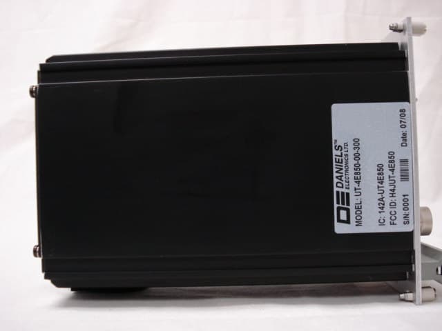
Click to zoom
Application Details
- Equipment Class
- TNB - Licensed Non-Broadcast Station Transmitter
- Date of Grant
- Sep 19, 2008
- Application Purpose
- Original Equipment
- Date of Application
- Sep 18, 2008
- Equipment Note
- MT-4E 800 MHz Transmitter
- Frequency Range
- 799.00000000 - 869.00000000
- Company
- Zetron
- Country
- Canada
Documents & Files
Document Text
Text extracted from the exhibit documents filed with the FCC. Open a document above to read the original.
Users Manual
© 2007 Daniels Electronics Ltd. All rights reserved. No part of this publication may be reproduced, stored in a retrieval system or transmitted in any form or by any means, electronic, mechanical, photocopying, recording or otherwise, without the prior written consent of Daniels Electronics Ltd. The stylized “Daniels Electronics Ltd.” and “DE” logo are registered Canadian and US trademarks of Daniels Electronics Ltd. The stylized “Daniels Electronics Ltd.” and “DE” logo are trademarks of Daniels Electronics Ltd. Document Number: Revision: Date: Daniels Electronics Ltd. Victoria, BC PRINTED IN CANADA Covers Models: UR-4E420-00-000 UT-4E450-00-800 UR-4E420-A0-000 UT-4E500-00-800 UR-4E460-00-000 UT-4E850-00-300 UR-4E460-A0-000 VR-4E150-00-000 UR-4E500-00-000 VR-4E150-A0-000 UR-4E800-A0-000 VT-4E150-00-800 UR-4E850-A0-000 MT-4E vhf & Uhf rEcEivEr & TransMiTTEr insTrUcTion ManUal 136-174 MHz / 406-470 MHz / 470-520 MHz / 799-869 MHz IM08-MT-4E-TXRX Project 1106 July 2008 MT-4E VHF & UHF Receiver & Transmitter Instruction Manual IM08-MT-4E-TXRX Project 1106 ii This document has been produced, verified and controlled in accordance with Daniels Electronics’ Quality Management System requirements. Please report any errors or problems to Daniels Electronics’ Customer Service Department. DOCUMENT CONTROL The user’s authority to operate this equipment could be revoked through any changes or modifications not expressly approved by Daniels Electronics Ltd. The AMBE+2™ voice coding Technology embodied in this product is protected by intellectual property rights including patent rights, copyrights and trade secrets of Digital Voice Systems, Inc. This voice coding Technology is licensed solely for use within this Communications Equipment. The user of this Technology is explicitly prohibited from attempting to extract, remove, decompile, reverse engineer, or disassemble the Object Code, or in any other way convert the Object Code into a human-readable form. U.S. Patent Nos. #5,870,405, #5,826,222, #5,754,974, #5,701,390, #5,715,365, #5,649,050, #5,630,011, #5,581,656, #5,517,511, #5,491,772, #5,247,579, #5,226,084 and #5,195,166. The design of this equipment is subject to change due to continuous development. This equipment may incorporate minor changes in detail from the information contained in this manual. This equipment has been tested and found to comply with the limits for a Class B digital device, pursuant to Part 15 of the FCC Rules and ICES 03. These limits are designed to provide reasonable protection against harmful interference in a residential installation. This equipment generates, uses and can radiate radio frequency energy and, if not installed and used in accordance with the instructions, may cause harmful interference to radio communications. However, there is no guarantee that interference will not occur in a particular installation. If this equipment does cause harmful interference to radio or television reception, which can be determined by turning the equipment off and on, the user is encouraged to try to correct the interference by one or more of the following measures: - Reorient or relocate the receiving antenna. - Increase the separation between the equipment and receiver. - Connect the equipment into an outlet on a circuit different from that to which the receiver is connected. - Consult the dealer or an experienced radio / TV technician for help. Operation is subject to the following two conditions: (1) this device may not cause interference, and (2) this device must accept any interference, including interference that may cause undesired operation of the device. NOTE Daniels Electronics Ltd. utilizes a three-level revision system. This system enables Daniels to identify the significance of a revision. Each element of the revision number signifies the scope of change as described in the diagram below. DOCUMENT REVISION DEFINITION Major Revisions: The result of a major change to product function, process or requirements. Minor Revisions: The result of a minor change to product, process or requirements. Editorial Revisions: The result of typing corrections or changes in formatting, grammar or wording. 1-0-0 Three-level revision numbers start at 1-0-0 for the first release. The appropriate element of the revision number is incremented by 1 for each subsequent revision, causing any digits to the right to be reset to 0. For example: If the current revision = 2-1-1 Then the next major revision = 3-0-0 If the current revision = 4-3-1 Then the next minor revision = 4-4-0 If the current revision = 3-2-2 Then the next editorial revision = 3-2-3 The complete revision history is provided at the back of the document. MT-4E VHF & UHF Receiver & Transmitter Instruction Manual IM08-MT-4E-TXRX Project 1106 iii RF Exposure Warning Exposure to radio frequency (RF) energy has been identified as a potential environmental factor that must be considered before a radio transmitter can be authorized or licensed. The FCC and IC have therefore developed maximum permissible exposure (MPE) limits for field strength and power density, listed in FCC 47 CFR 1.1310 and IC RSS-102 Issue 2 Sect 4. The FCC has furthermore determined that determination of compliance with these exposure limits, and preparation of an Environmental Assessment (EA) if the limits are exceeded, is necessary only for facilities, operations and transmitters that fall into certain risk categories, listed in FCC 47 CFR 1.1307 (b), Table 1. All other facilities, operations and transmitters are categorically excluded from making such studies or preparing an EA, except as indicated in FCC 47 CFR 1.1307 (c) and (d). Revised FCC OET Bulletin 65 (Edition 97-01) and IC RSS-102 Issue 2 provide assistance in determining whether a proposed or existing transmitting facility, operation or device complies with RF exposure limits. In accordance with OET Bulletin 65, FCC 47 CFR 1.1307 (b) and RSS-102 Issue Sect 2.5, this Daniels Electronics Ltd. transmitt…
Text truncated - open the document above for the full version.
Cover Letter(s)
JULY 09, 2008 Federal Communications Commission, Equipment Approval Services, P.O. Box 358315 Pittsburgh, PA 15251-5315 FCC ID: H4JUT-4E850 Model #: UT-4E850-00-300 Product Name: MT-4E 800MHZ TRANSMITTER Request for Confidentiality Pursuant to Sections 0.457(d)(1)(ii) and 0.459 of the commission’s rules, we hereby request that the following documents be held confidential: • Operational Description • All Schematics • Tune Up Procedure • Parts Listings These materials contain trade secrets and proprietary information and are not customarily released to the public. The public disclosure of this information might be harmful to the company and provide unjustified benefits to our competitors. Dated this 09 Day of JULY 20 08 By: MICHAEL J CYR Signature Printed Title: COMMUNICATION SYSTEMS DESIGNER On behalf of : DANIELS ELECTRONICS LTD Telephone: (250)382-8268
Cover Letter(s)
July 09, 2008 Federal Communications Commission Authorization & Evaluation Division 7345 Oakland Mills Road Columbia, Maryland 21046 Authority to Act as Agent On our behalf, I appoint Flom Test Labs located at 3356 N. San Marco Pl, Chandler, AZ to act as our agent in the preparation of this application for equipment certification in all FCC Matters. I certify that submitted documents properly describe the device or system for which equipment certification is sought. I also certify that each unit manufactured, imported or marketed, as defined in the Federal Communications Commission’s regulations will have affixed to it a label identical to that submitted for approval with this application. This is to advise that we are in full compliance with the Anti-Drug Abuse Act. The Applicant is not subject to a denial of federal benefits pursuant to Section 5301 of the Anti-Drug Abuse Act of 1988, 21 USC 862, and no party to the application is subject to a denial of federal benefits pursuant to that section. For instances where our authorized agent signs the application for certification on our behalf, I acknowledge that all responsibility for complying with the terms and conditions for certification, as specified by Flom Test Labs, still resides with Daniels Electronics Ltd located at 43 Erie St, Victoria, BC. Dated this 09 Day of JULY 20 08 Agency agreement expiration date: JUL 09, 2009 By: MICHAEL J CYR Signature Printed Title: COMMUNICATION SYSTEM DESIGNER On behalf of : DANIELS ELECTRONICS LTD Telephone: (250)382-8268
Cover Letter(s)
JULY 09, 2008 Equipment Authorization Division Federal Communications Commission 7435 Oakland Mills Road Columbia, MD 21046 FCC ID: H4JUT-4E850 Product Name: UT-4E850 TRANSMITTER Compliance with 47 CFR Part 90.203 (g), (j)(3) Pursuant to 47 CFR Sections 90.203(g) and (j)(3) of the commission’s rules we hereby certify that the above listed transmitter is fully compliant with these guidelines for the following listed reasons. The UT-4E850 transmit frequency is capable of being programmed within the range of 799 to 869 MHz via an external USB connection and Radio Services Software (RSS) package, which is made available only to service and/or maintenance personnel. The narrowband setting of this equipment operates from 0.5 to 3 Watts and meets a spectrum efficiency standard of one voice channel per 12.5 kHz of channel bandwidth in analog transmit mode. In the digital transmit mode, the equipment supports the minimum data rate of 9600 bits per second per 12.5 kHz of channel bandwidth. Dated this 09 Day of JULY 20 08 By: MICHAEL J CYR Signature Printed Title: COMMUNICATION SYSTEMS DESIGNER On behalf of : DANIELS ELECTRONICS LTD Telephone: (250)382-8268
Cover Letter(s)
American Telecommunications Certification Body Inc. 6731 Whittier Ave, McLean, VA 22101 September 8, 2008 RE: FCC ID: H4JUT-4E850_ATCB006714 Attention: Hoosamuddin S. Bandukwala I have a few comments on this Application. Please note that further comments may arise in response to answers provided to the questions below. 1. Please provide the parts list for this device. 2. Please note that the confidentiality request does not include the part list just requested. If the parts list is to be have confidentiality status, please rewrite the confidentiality request to include the parts list. 3. Please note that the operational description states the device can be adjusted from 0.5W to 8W output power. Please note that it is not clear from the description is the DSP activated power control/enable line is then used to reduce power to a specified output or for other control. Please also note that the manual states the output power for this device is 0.5 to 4W. Please note that the report shows the device max output is only 3.85W. Please explain why there is such a big gap in the measured and rated powers from the operational description. Please retest the device to the maximum output power available. Please review ALL documentation and make sure that all exhibits agree. 4. Please note that on page 16 of the test report you record conducted antenna terminal power but reference it to an ERP limit. Please correct and explain. 5. Please note that the report on page 17 states that a tunable notch filter was used in the measurement of conducted spurious emissions. However, the frequency to which the notch filter was tuned is not given. Please state the actual frequency to which the notch filter was tuned. Please remember that, while this may be the case, I cannot assume it was tuned to filter out the fundamental. This has to be specified in the report. 6. Please note that the Audio Low Pass Filter plot on page 32 of the report contains no data. Please explain and please provide as necessary. 7. Please note that the audio frequency response plot on page 33 of the report seems to be missing data. For example you state that you tested from 100Hz to 50kHz, however the plot does not look like this is the case. Please explain and please show all data. 8. Please note that some of the documentation states that this device can be used as a repeater. Repeaters would require MPE calculations and an MPE report. Also, it is not clear from the documentation is this device is ALWAYS used as a licensed station, or if it can or will ever be used only in conjunction with a licensed base station (i.e. possibly a repeater). If this device in not ALWAYS used in a fixed location in which it is licensed, then you must provide an MPE report. Please explain and please provide the appropriate information as needed. 9. Please explain how the label is permanent and how it meets the labeling requirements of part 2. IC app 10. Please note that the test report does not adequately address the Industry Canada standards. There is no mention of what RSS in intended to be tested nor is there any indication that any RSS requirements have been reviewed and verified for compliance. Please provide an accurate and adequate cross reference to the appropriate RSS for Canada. 11. Please note that in reference to item 8 above, if this is not ALWAYS used as a fixed licensed station You will have to complete the RSS012 annex A and provide a value for MPE. Please explain and please provide the appropriate information as needed. z Page 2 September 8, 2008 Dennis Ward mailto:[email protected] The items indicated above must be submitted before processing can continue on the above referenced application. Failure to provide the requested information may result in application termination. Except as described in §0.459, correspondence and responses should be considered part of the permanent submission and may be viewed from the Internet after a Grant of Equipment Authorization is issued. Please do not respond to this correspondence using the email reply button. In order for your response to be processed expeditiously, you must submit your documents through the AmericanTCB.com website. Also, please note that partial responses increase processing time and should not be submitted. Any questions about the content of this correspondence should be directed to the sender.
Cover Letter(s)
1. A parts list will be provided. 2. See #1 3. The difference between 3.85W and 4W is 0.17 dB. The operational description has been edited to replace the 8W reference. 4. The limit includes the antenna at the time of licensing. The conducted value plus the antenna gain must be below the limit. 5. The report has been edited to state that the notch filter was tuned to match the fundamental frequency. 6. The test has been performed again and the new data has been added. 7. The test has been performed again and the new data has been added. 8. RF exposure is addressed on page iii of the user’s manual. There is now a comment about licensing of a repeater. 9. As this is a Part 90, I believe that you are looking for the label and/or manual to state the following: This device complies with part 15 of the FCC Rules. Operation is subject to the condition that this device does not cause harmful interference. Please confirm if this is the correct selection. 10. A cross reference for FCC part 90 to RSS-119 will be sent to ATCB. 11. See #8.
External Photos
Front Panel View Rear Panel View Left Side View Right Side View Bottom End View Top End View UT-4E850-00-300
ID Label/Location Info
FRONT PANEL BOTTOM TOP LEFT SIDE COVER 2.250 1.375 DATE: 9 July 2008 TITLE: UT-4E850 3 Watt 800MHz TX Body Tube Label Format and Location DRAWN BY: M. Cyr REV DATE: 9 July 2008 DWG No: DANIELS ELECTRONICS LTD. TM 1 11 21 2 12 22 3 13 23 4 14 24 5 15 25 6 16 26 7 17 27 8 18 28 9 19 29 10 20 30 A
ID Label/Location Info
1 dward To: Sandy Valentine Subject: RE: Daniel's Electronics H4JUT-4E850_ATCB006714 As for the permanent IC / FCC label set, it is a label manufactured by 3M with the following specifications: ‐ thermal ink transfer printable label ‐ tamper evident vinyl label ‐ Tested over full product range : ‐40 to +121 degrees C The following is the 3M link to the datasheet: http://multimedia.3m.com/mws/mediawebserver?66666UuZjcFSLXTt58&2m8s6EVuQ EcuZgVs6EVs6E666666‐‐
Test Report
Flom Test Labs 3356 N. San Marcos Place, Suite 107 Chandler, Arizona 85225-7176 (866) 311-3268 phone, (480) 926-3598 fax p0870001, d0880013 Rev 4.0 For MFA internal use only Please keep this page with the report in out files. Applicant: Daniels Electronics Ltd. Model: UT-4E850-00-300 FCC ID: H4JUT-4E850 Formulaire: P:\\Users\\Marks\\FCC.Certification.General_calrevised10_06.rtf Last Modified: July 8, 2008 Purpose: Part 74 MFA Project ID: p0870001 Client ID: DANIELS ELECTR MFA Document ID: d0880013 Date: August 14, 2008 This Printing July 8, 2008 Writer: HSB/je ___ < Check here if this report has been manually modified. ___ < Check here if this report was made from another report. Original document : ___ < Check here if this report varies significantly from the formulaire Rev 1.0 Mark Sechrist July 8, 2008 Flom Test Labs 3356 N. San Marcos Place, Suite 107 Chandler, Arizona 85225-7176 (866) 311-3268 phone, (480) 926-3598 fax p0870001, d0880013 Rev 4.0 Date: August 14, 2008 Applicant: Daniels Electronics Ltd. 43 Erie Street Victoria BC V8V 1P8 Canada Attention of: Mike Cyr Ph: 250-382-8268 Fax: 250-382-6139 Email: [email protected] Equipment: UT-4E850-00-300 FCC ID: H4JUT-4E850 FCC Rules: 90 Gentlemen: Enclosed please find your copy of the Engineering Test Report for which you are subject to the restrictions as listed on the attached summary. Once a Telecommunication Certification Body (TCB) issues a Grant the Federal Communication Commission (FCC) has 30 days to review the application and request added information. It is your decision whether or not to market the equipment subject to a possible recall before the end of the 30 days. If your equipment is still retained by us, it will be returned to you 30 days after approval is achieved. Our invoice for services has been directed to your Accounts Payable Department. For any additional information please contact us. Thank you. Sincerely yours, Hoosamuddin S. Bandukwala, Lab Director Flom Test Labs 3356 N. San Marcos Place, Suite 107 Chandler, Arizona 85225-7176 (866) 311-3268 phone, (480) 926-3598 fax p0870001, d0880013 Rev 4.0 Summary of Restrictions 1. All submissions to the FCC are subject to their Examiner's interpretation. 2. Please allow from 60 to 90 days before hearing from the FCC with regard to any submission. 3. The FCC can set aside any action; modify or set aside any action, within 30 days. (FCC Rule 1.108, 1.113). 4. Under Rule 2.803, if device is not type accepted/certificated then it must not be sold, leased, offered for sale, imported, shipped or distributed or advertised for sale. 5. FCC can revoke its certificates at any time if the equipment does not meet or continue to meet their Rules. (Rule Parts 2.927, 2.939). 6. FCC can request a sample at any time (2.936). Flom Test Labs 3356 N. San Marcos Place, Suite 107 Chandler, Arizona 85225-7176 (866) 311-3268 phone, (480) 926-3598 fax p0870001, d0880013 Rev 4.0 Date: August 14, 2008 Federal Communications Commission Via: Electronic Filing Attention: Authorization & Evaluation Division Applicant: Daniels Electronics Ltd. Equipment: UT-4E850-00-300 FCC ID: H4JUT-4E850 FCC Rules: 90 Dear Sir or Madam: On behalf of the Applicant, enclosed please find Application Form 731, Engineering Test Report and all pertinent documentation, the whole for approval of the referenced equipment as shown. We trust the same is in order. Should you need any further information, kindly contact the writer who is authorized to act as agent. Sincerely yours, Hoosamuddin S. Bandukwala, Lab Director Flom Test Labs 3356 N. San Marcos Place, Suite 107 Chandler, Arizona 85225-7176 (866) 311-3268 phone, (480) 926-3598 fax p0870001, d0880013 Rev 4.0 Test Report for FCC ID: H4JUT-4E850 Model: UT-4E850-00-300 to Federal Communications Commission Rule Part(s) 90 Date of report: August 14, 2008 Date of Revised Report: September 10, 2008 On the Behalf of the Applicant: Daniels Electronics Ltd. At the Request of: Daniels Electronics Ltd. 43 Erie Street Victoria BC V8V 1P8 Canada Attention of: Mike Cyr Ph: 250-382-8268 Fax: 250-382-6139 Email: [email protected] Sincerely yours, Hoosamuddin S. Bandukwala, Lab Director Flom Test Labs 3356 N. San Marcos Place, Suite 107 Chandler, Arizona 85225-7176 (866) 311-3268 phone, (480) 926-3598 fax p0870001, d0880013 Rev 4.0 Revision History Revision Date Revised By Reason for revision 1.0 August 14, 2008 J Erhard Original Document 2.0 September 4, 2008 S Valentine Edit customer contact information 3.0 September 9, 2008 J Erhard Edit technical data per TCB request 4.0 September 17, 2008 J Erhard Edit technical data per TCB request Flom Test Labs 3356 N. San Marcos Place, Suite 107 Chandler, Arizona 85225-7176 (866) 311-3268 phone, (480) 926-3598 fax p0870001, d0880013 Rev 4.0 List of Exhibits (FCC Certification (Transmitters) - Revised 9/28/98) Applicant: Daniels Electronics Ltd. FCC ID: H4JUT-4E850 By Applicant: 1. Letter of Authorization 2. Confidentiality Request: 0.457 And 0.459 3. Identification Drawings, 2.1033(c)(11) Label Location of Label Compliance Statement Location of Compliance Statement 4. Photographs, 2.1033(c)(12) 5. Documentation: 2.1033(c) (3) User Manual (9) Tune Up Info (10) Schematic Diagram (10) Circuit Description Block Diagram Parts List Active Devices 6. MPE/SAR Report By F.T.L.: A. Testimonial & Statement of Certification Flom Test Labs 3356 N. San Marcos Place, Suite 107 Chandler, Arizona 85225-7176 (866) 311-3268 phone, (480) 926-3598 fax p0870001, d0880013 Rev 4.0 The Applicant has been cautioned as to the following: 15.21 Information to the User. The users manual or instruction manual for an intentional radiator shall caution the user that changes or modifications not expressly approved by the party responsible for compliance could void the user's authority to operate the equipment. 15.27(a) Special Accessories. Equipment marketed to a consumer must be capable of complying with the necessary regulations in the configuration in which the equipme…
Text truncated - open the document above for the full version.
Contact Information
Applicant
Werner Hoepf(Senior Compliance Analyst)
Technical Specifications
| # | Rule Parts | Frequency Range | Power Output | Emission | Tolerance |
|---|---|---|---|---|---|
| 6 | 9 | 799 MHz - 869 MHz | 3.85 W | 9K20F1D | 300 Hz |
Other Applications from Zetron
H4JCASC165B
Feb 18, 2020Cascade VHF Transceiver
Equipment Class
TNB - Licensed Non-Broadcast Station Transmitter
H4JAMP-4-800
Aug 17, 2014700/800 MHz 30W POWER AMPLIFIER
Equipment Class
AMP - Amplifier
H4JAMP-4-410
Dec 27, 2012UHF 30W POWER AMPLIFIER
Equipment Class
AMP - Amplifier
H4JAMP-4-470
Dec 27, 2012UHF 30W POWER AMPLIFIER
Equipment Class
AMP - Amplifier
H4JAMP-4-150
Dec 14, 201130W VHF POWER AMPLIFIER
Equipment Class
AMP - Amplifier