H4JVT-3A130-F25kHz AM TRANSMITTER
Zetron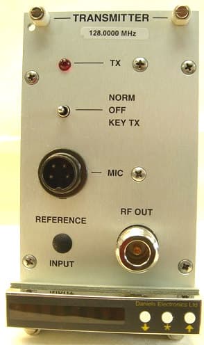
Click to zoom
Application Details
- Equipment Class
- TNB - Licensed Non-Broadcast Station Transmitter
- Date of Grant
- Nov 06, 2006
- Application Purpose
- Original Equipment
- Date of Application
- Nov 06, 2006
- Equipment Note
- 25kHz AM TRANSMITTER
- Frequency Range
- 118.00000000 - 136.97500000
- Company
- Zetron
- Country
- Canada
Documents & Files
Document Text
Text extracted from the exhibit documents filed with the FCC. Open a document above to read the original.
Users Manual
User's Guide The VT-3A130 Transmitter is a synthesized multichannel AM transmitter designed to interface with the MT-3 Repeater Systems, while still maintaining MT-2 system compatibility. Both MT-3 systems are characterized by dependable low maintenance performance under the most severe environmental conditions. In addition, all units are burnt-in for 24 hours and are accompanied by a complete test report. The VT-3A130 Transmitter operates in the 118 - 137 MHz aviation band. The transmitter’s frequency stability is controlled by an OST-3A138 AM Enhanced Synthesizer. The Synthesizer module can be programmed for up to 16 channels. A channel programmer can preprogram the first 15 channels; channel 16 can be programmed from the front panel and channel 1 can be programmed by the four BCD switches located on the MT-3 AM Transmitter Main Board. The VT-3A130 modular transmitter family is compatible with all Daniel’s subrack and base station enclosures. Transmitter Features Compatibility MT-2 Series and MT-3 Series Radio Systems Frequency Generation Synthesized (internal plug-in module) Channel Selection In 25 kHz increments selected by four BCD switches Preset capability for 16 channels selectable through external control Front Panel Control One 3 position switch: - NORM (repeat mode) - OFF - KEY TX PTT Activation: - Active to ground with time-out timer - Active to ground without time-out timer - Microphone activated without time-out timer - Front Panel switch (KEYED) without time-out timer, (NORM) with or without time-out-timer. Amplifier Enable Active to ground Performance Specifications Overall Transmitter Specifications Parameter Specification Reference Operating Temperature Range -30°C to +60°C Optional -40°C to +60°C Optional -50°C to +40°C Type MT-3 Series Transmitter Family VT-3A130 Frequency Range 118 - 137 MHz System Impedance 50 ΩType N RF Power Output 1.0 – 3.0 Watts adjustable (carrier only) RTCA DO-186A Paragraph 2.3.1 Emission of Radio Freq. Energy More than 50 dB below carrier RTCA DO-186A Paragraph 2.3.7(b) Carrier Noise Level More than 45 dB below carrier RTCA DO-186A Paragraph 2.3.6 Duty Cycle 100%; Continuous operation from -30°C to +60°C Optional -40°C or -60°C Channel Spacing 25 KHz Emission Identifier 6K00A3E and 5K6A3E Amplitude Modulation Operating Humidity 95% Relative Humidity (Non-condensing) at +25°C Operating Voltage +13.8 VDC Nominal +9.5 VDC regulated Active Current +13.8 VDC supply < 2A @ 25°C, at 3 Watts RF output <2.5A -40 ̊C to +60 ̊C Channel Selection In 25 kHz increments selected by four BCD switches. Preset capability for 16 channels selectable through external control. Frequency Stability Standard: ±1 ppm -40°C to +60°C ± 2 ppm, -50°C to -40°C RTCA DO-186A Paragraph 2.3.11 FCC Type Approval H4JVT-3A130-F Industry Canada Certification 142A-VT3A130F PTT Time-Out-Timer Selectable 1 seconds to 8 hours.(factory set 5 min) Standby Current (9.5 VDC) and Rise time Refer to Transmitter Standby Modes in Theory of Operation Audio Specifications Parameter Specification Reference Audio Input -30 to 0 dBm into a 600Ω balanced load Audio Frequency Response Flat audio; +1/-5 dB: 350 Hz - 2.5 kHz RTCA DO-186A Paragraph 2.3.5.1 Audio Frequency Distortion 1 kHz tone, 50kHz Low Pass Filter Less than 5%+25 ̊C at 85% modulation Less than 10% -40 ̊C to +60 ̊C at 85% modulation Less than 15% >+40 ̊C to +60 ̊C RTCA DO-186A Paragraph 2.3.4 Synthesizer Specifications RF Power Output: +3 dBm Nominal Physical Specifications Physical Dimensions: Width: 7.1 cm (2.8 in) Height: 12.8 cm (5.05 in) Depth: 19 cm (7.5 in) Module Weight: 1.4 kg (3.0 lb.) Corrosion Prevention: Anodized aluminum construction. Stainless steel hardware. Selectively conformal coated glass epoxy 2 and 4 layer printed circuit boards. Gold plated module connectors. Module Design: Compact Eurostandard modular design. Plug-in modules mate with Daniels standard MT-3 repeater subrack. Subracks and modules comply with IEEE 1101, DIN 41494 and IEC 297-3 (mechanical size / modular arrangement). External Connections: RF Connection: Type N connector located on the transmitter module front panel. Motherboard Connections (Audio, Power, and Control) are made through a 48 pin, gold plated, type F connector on the rear of the transmitter module. User connection is made through a mated “mother board” assembly of the repeater subrack. Type F standard connector complies with DIN 41612 Level 2 (200 mating cycles, 4 day 10 ppm SO2 gas test with no functional impairment and no change in contact resistance). Frequency Select Handle Performance Specifications Temperature Range: -30°C to +60°C.(Optional -40°C to +60°C) Supply Voltage: +9.5 VDC Supply Current: Less than 35 mA operate; less than 4.0 mA standby mode
Cover Letter(s)
OCTOBER 31, 2006 Federal Communications Commission Equipment Authorisation and Evaluation Division FCC ID: H4JVT-3A130-F Product Name: 25 KHZ AM TRANSMITTER Request for Confidentiality Pursuant to Sections 0.457 and 0.459 of the commission’s rules, we hereby request that the following documents be held confidential: • Circuit Description / file name "Operational_Desc.pdf" • Block Diagram / file name "Block_Diagram.pdf" • Tune Up Procedure / file name "Alignment_Proc.pdf" • All Schematics / file name "Schematic_DWG.pdf" • All Parts Lists (BOMs) / file name "Parts List.pdf" These materials contain trade secrets and proprietary information and are not customarily released to the public. The public disclosure of this information might be harmful to the company and provide unjustified benefits to our competitors. Pursuant to DA 04-1705 June 15, 2004 of the Commission’s public notice, we also request temporary confidential treatment of information accompanying this application as outlined below: • External Photos / file name "external photos.pdf" • Internal Photos / file names "internal photos 1.pdf", "internal photos 2.pdf" • Test Setup Photos / file name "teststp.pdf" • User’s Manual / file name "Users_guide.pdf" Dated this 31 Day of OCTOBER 20 06 By: MICHAEL J CYR Signature Printed Title: COMMUNICATION SYSTEMS DESIGNER On behalf of : DANIELS ELECTRONICS LTD Telephone: (250)382-8268
External Photos
VT-3A130-SYF410 External Pictures
ID Label/Location Info
5 Label format and location diagram DA TE: 29 JUN 06 TITLE: VT-3A130-SYF410 AM TX Front Panel Label Format and Location DRAWN BY: L Jo e RE V DATE: 29 June 2006DWG No: DANIELS ELECTRONICS LTD. TM A ON / OFF/ PTT SWITCH N -T YPE FEMALE CHASSIS JACK SMA REF ERENCE INPUT JACK ( Optional ) TRANSMIT INDICATOR LED TRANSMITT ER MODEL IDENT IFIER MICROPHONE CONNECT OR TRANSMITTER TX REFERENCE INPUT OFF NORM KEY TX MIC RF OUT FREQUENCY DECREASE BUT TON FREQUENCY INCREASE BUTTON OPT IONS BUTTON * Da nie ls Electron ics Ltd .312 1.062 1.062 .312 6 FRONT PANEL BOTTOM TOP LEFT SIDE COVER EQUIPMENT ID LABEL FORMAT & LOCATION VT-3A130-SYF410 3 Watt AM Transmitter 2.250 1.375 DA TE: 29 June 2006 TITLE: VT-3A13 0-SYF410 AM TX Body Tube L abel Format and Loca tion DRAWN BY: L. Joe RE V DATE: 14 Aug 2006DWG No: DANIELS ELE CTRONICS LTD. TM A
RF Exposure Info
Applicant: Daniel Electronics Ltd Page 1 of 2 FCC ID: H4JVT-3A130-F Report #: 2283AUT6 FCC RF Exposure Requirements General information : FCC ID: H4JVT-3A130-F Device category: Mobile per Part 2.1091 Environment: Controlled Exposure Fixed devices that operate under Part 87 of this chapter are subject to routine environmental evaluation for RF exposure prior to equipment authorization or use if they operate at frequencies of 1.5 GHz or below and their effective radiated power (ERP) is 1.5 watts or more. However, compliance with the power density limits of 1.1310 is not required. Antenna: The manufacturer does not specify any antenna to be used with this device. This device has provisions for operation in a fixed location. Configuration Antenna p/n Type Max. Gain (dBi) Fixed Any omni 9 Operating configuration and exposure conditions: The conducted output power is 3 watts. Typical use qualifies for a maximum duty cycle factor of 50%. The manufacturer also markets this device only for occupation use. But because of a fixed structure and not being able to control exposure in all cases we have used the uncontrolled expose limit. - Part 2.1091 states that devices are excluded from routine evaluation if the EIRP is less than 2.46Watt (or 1.5WERP). - Fixed Operation: The maximum antenna gain that can be used is 9 dBi. A coaxial cable of the type RG 58 has a loss of 1dB for a length of 15 feet. MPE Calculation : The minimum separation distance is calculated as follows: The limit for uncontrolled exposure environment below 300 MHz is fixed at 0.2 mW/cm 2 . Applicant: Daniel Electronics Ltd Page 2 of 2 FCC ID: H4JVT-3A130-F Report #: 2283AUT6 Channel frequency: 118 to 137 MHz The conducted power output is 3 watt. The coax loss was taken as 1 dB. Antenna gain was taken as 9 dBi 50% talk time in 30 minutes which reduces the power to 1.5 Watts in the formula below. The value for S is fixed at 0.2 mW/cm 2 which in the formulas below is shown as 300/1500. required for compliance Rinches24.16= distance in centimeters R61.366= Rinches R 2.54 := R Po Gn⋅() 4π⋅S⋅ () := Gn6.31= mW cm 2 S0.2= Gn10 G 10 := gain numeric 1500 for uncontrolled exposure gain in dBi G8= S f 1500 := GdBd2.15+1−:= Frequency in MHz f300:= antenna gain dBd6.85:=mWattsPo1500:= Conclusion: The device complies with the MPE requirements by providing a safe separation distance of 62 cm between the antenna, including any radiating structure, and any persons when normally operated . Proposed RF exposure safety information to include in User’s Manual : “FCC RF Exposure Requirements: CAUTION: The antenna(s) used for this transmitter must not be co-located or operating in conjunction with any other antenna or transmitter. This device is approved with emissions having a source-based time-averaging duty factor not exceeding 50%. Antenna Installation: - Antennas used for this transmitter must not exceed an antenna gain of 9 dBi with a minimum cable loss of 1dB. - Failure to observe these restrictions will result in exceeding the FCC RF exposure limits.
Test Report
FCC PART 87 TEST REPORT APPLICANT Daniel Electronics Ltd. 43 Erie Street Victoria BC V8V 1P8 Canada FCC ID H4JVT-3A130-F MODEL NUMBER VT-3A130-SYF410 PRODUCT DESCRIPTION 25 kHz AM TRANSMITTER DATE SAMPLE RECEIVED 8/2/2006 DATE TESTED 8/18/2006 TESTED BY Nam Nguyen APPROVED BY Mario R. de Aranzeta TIMCO REPORT NO. D\Danelec\2283AUT6\2283AUT6TestReport.doc TEST RESULTS PASS FAIL THE ATTACHED REPORT SHALL NOT BE REPRODUCED EXCEPT IN FULL WITHOUT THE WRITTEN APPROVAL OF TIMCO ENGINEERING, INC. 849 NW STATE ROAD 45 NEWBERRY, FL 32669 USA PH: 888.472.2424 OR 352.472.5500 FAX: 352.472.2030 EMAIL: [email protected] HTTP: //WWW.TIMCOENGR.COM Certificate # 0955-01 Certificate # 0955-01 Applicant: Daniel Electronics Ltd. FCC ID: H4JVT-3A130-SYF410 Report: D\Danelec\2283AUT6\2283AUT6TestReport.doc Page 2 of 17 TABLE OF CONTENTS STATEMENT OF COMPLIANCE.................................................................................. 3 REPORT SUMMARY................................................................................................... 4 TEST SYSTEM ........................................................................................................... 4 DUT SPECIFICATION................................................................................................. 5 EMC EQUIPMENT LIST ............................................................................................. 6 TEST PROCEDURE ................................................................................................... 7 RF POWER OUTPUT .................................................................................................. 9 MODULATION CHARACTERISTICS.......................................................................... 10 OCCUPIED BANDWIDTH ......................................................................................... 13 SPURIOUS EMISSIONS AT ANTENNA TERMINALS (CONDUCTED)........................... 14 FIELD STRENGTH OF SPURIOUS EMISSIONS......................................................... 15 FREQUENCY STABILITY.......................................................................................... 16 POWER LINE CONDUCTED INTERFERENCE........................................................... 17 Certificate # 0955-01 Applicant: Daniel Electronics Ltd. FCC ID: H4JVT-3A130-SYF410 Report: D\Danelec\2283AUT6\2283AUT6TestReport.doc Page 3 of 17 STATEMENT OF COMPLIANCE This equipment has been tested in accordance with the standards identified in the referenced test report. To the best of my knowledge and belief, these tests were performed using the measurement procedures described in this report and demonstrate that the equipment complies with the appropriate standards. No modifications were made to the equipment during testing in order to demonstrate compliance with these standards. I attest that the necessary measurements were made by me or under my supervision, at Timco Engineering, Inc. located at 849 N.W. State Road 45, Newberry, Florida 32669 USA. Authorized by: Mario R. de Aranzeta Function: Engineer Date: 8/29/2006 Tested by: Nam Nguyen Certificate # 0955-01 Applicant: Daniel Electronics Ltd. FCC ID: H4JVT-3A130-SYF410 Report: D\Danelec\2283AUT6\2283AUT6TestReport.doc Page 4 of 17 REPORT SUMMARY Purpose of Report: To demonstrate the DUT in compliance with FCC CDR 47 Part 80 requirements. Disclaimer: The test results relate only to the items tested. Applicable Standards: TIA 603, FCC CFR 47 Part 87 TEST SYSTEM Test Facility: The test sites used by Timco Engineering Inc. for collecting radiated and conducted emission data are located at 849 NW State Road 45 Newberry, FL 32669 USA. Test Condition of Laboratory: Temperature: 26ºC Relative humidity: 50% Test Exercise (e.g software description, test signal, etc.): The DUT was placed in continuous transmit mode of operation. Modification to the DUT: No modification was made to the DUT during testing. Test Accessories: NA Certificate # 0955-01 Applicant: Daniel Electronics Ltd. FCC ID: H4JVT-3A130-SYF410 Report: D\Danelec\2283AUT6\2283AUT6TestReport.doc Page 5 of 17 DUT SPECIFICATION Manufacturer: Daniel Electroncis Ltd. DUT Description: Non-Broadcast Station VHF Transmitter FCC ID: H4JVT-3A130-F Model Number: VT-3A130-SYF410 Operating Frequency: 118.00 MHz – 137.00 MHz No. of Channels: 16 Modulation: AM Type of Emission: 6K00A3E Authorized Bandwidth: 25 kHz Power Source: DC Power 13.8 Vdc DC Voltages and Current into Final Amplifier High Power – High: (13.8Vdc)(1.0A) = 13.8 Watts Test Item: Prototype Pre-Production Production Type of Equipment: Fixed Mobile Portable Antenna: NA Antenna Connector: N-Female Certificate # 0955-01 Applicant: Daniel Electronics Ltd. FCC ID: H4JVT-3A130-SYF410 Report: D\Danelec\2283AUT6\2283AUT6TestReport.doc Page 6 of 17 EMC EQUIPMENT LIST Device Manufacturer Model Serial Number Cal/Char Date Due Date Analyzer Tan Tower Spectrum Analyzer HP 8566B Opt 462 3138A07786 3144A20661 CAL 12/7/05 12/7/07 Analyzer Tan Tower RF Preselector HP 85685A 3221A01400 CAL 12/7/05 12/7/07 Analyzer Tan Tower Quasi-Peak Adapter HP 85650A 3303A01690 CAL 12/8/05 12/8/07 Analyzer Tan Tower Preamplifier HP 8449B- H02 3008A00372 CAL 12/8/05 12/8/07 Antenna: Biconnical Electro- Metrics BIA-25 1171 CAL 4/29/05 4/29/07 Antenna: Log-Periodic Electro- Metrics LPA-25 1122 CAL 8/26/04 8/26/06 Antenna: Double- Ridged Horn Electro- Metrics RGA-180 2319 CAL 12/29/04 12/29/06 LISN Electro- Metrics ANS-25/2 2604 CAL 8/27/04 8/27/06 Termaline Wattmeter Bird Electronic Corporation 611 16405 CAL 7/16/04 7/16/06 Certificate # 0955-01 Applicant: Daniel Electronics Ltd. FCC ID: H4JVT-3A130-SYF410 Report: D\Danelec\2283AUT6\2283AUT6TestReport.doc Page 7 of 17 TEST PROCEDURE Power Line Conducted Interference: The procedure used was TIA 603 using a 50uH LISN. The bandwidth of the spectrum analyzer was 10 kHz with an appropriate sweep speed. The spectrum was scanned from 0.15 to 30 MHz. Bandwidth 20 dB: The measurements were made with the spectrum anal…
Text truncated - open the document above for the full version.
Contact Information
Applicant
Werner Hoepf(Senior Compliance Analyst)
Test Firm
Timco Engineering, Inc.Sid Sanders
Technical Specifications
| # | Rule Parts | Frequency Range | Power Output | Emission | Tolerance |
|---|---|---|---|---|---|
| 1 | 87 | 118 MHz - 136.975 MHz | 3 W | 6K00A3E | 1.0000000000 ppm |
Other Applications from Zetron
H4JCASC165B
Feb 18, 2020Cascade VHF Transceiver
Equipment Class
TNB - Licensed Non-Broadcast Station Transmitter
H4JAMP-4-800
Aug 17, 2014700/800 MHz 30W POWER AMPLIFIER
Equipment Class
AMP - Amplifier
H4JAMP-4-410
Dec 27, 2012UHF 30W POWER AMPLIFIER
Equipment Class
AMP - Amplifier
H4JAMP-4-470
Dec 27, 2012UHF 30W POWER AMPLIFIER
Equipment Class
AMP - Amplifier
H4JAMP-4-150
Dec 14, 201130W VHF POWER AMPLIFIER
Equipment Class
AMP - Amplifier