H5P-FC200NJT499WLAN Unit
Topcon Corporation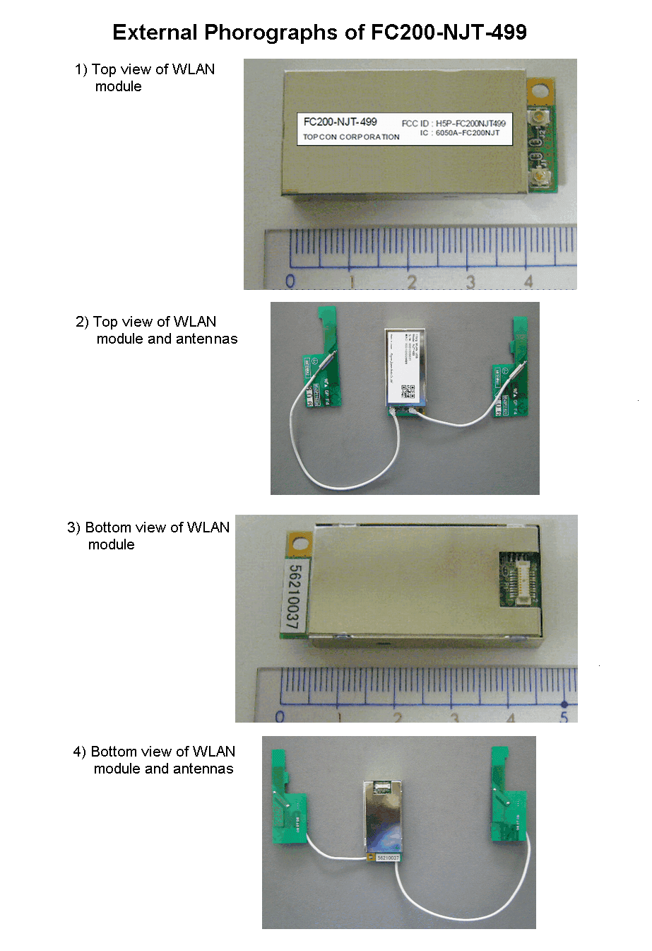
Click to zoom
Application Details
- Equipment Class
- DTS - Digital Transmission System
- Date of Grant
- Apr 04, 2007
- Application Purpose
- Original Equipment
- Date of Application
- Apr 04, 2007
- Equipment Note
- WLAN Unit
- Frequency Range
- 2412.00000000 - 2462.00000000
- Company
- Topcon Corporation
- Country
- Japan
Documents & Files
Document Text
Text extracted from the exhibit documents filed with the FCC. Open a document above to read the original.
Users Manual
1 Ver1.1 November 16, 2006 TOPCON FC200-NJT-499 User’s Manual 2 FCC Notices This device complies with Part 15 of the FCC Rules. Operation is subject to the following two conditions: (1) This device may not cause harmful interference, and (2) This device must accept any interference received, including interference that may cause undesired operation. CAUTION: Change or modification not expressly approved by the party responsible for compliance could void the user’s authority to operate this equipment. CAUTION: In order to comply with FCC radio-frequency radiation exposure guidelines for an uncontrolled exposure, this device and its antenna must not be co-located or operating in conjunction with any other antenna or transmitter. NOTE: This equipment has been tested and found to comply with the limits for a Class A digital device, pursuant to Part 15 of the FCC Rules. These limits are designed to provide reasonable protection against harmful interference when the equipment is operated in a commercial environment. This equipment generates, uses and can radiate radio frequency energy and, if not installed and used in accordance with the instruction manual, may cause harmful interference to radio communications. Operation of this equipment in a residential area is likely to cause harmful interference in which case the user will be required to correct the interference at his or her own expense. NOTE: The device to which FC200-NJT-499 is installed must display "Contains TX FCC ID: H5P-FC200NJT499". IC Notices CAUSION: Operation is subject to the following two conditions: (1) this device may not cause interference, and (2) this device must accept any interference, including interference that may cause undesired operation of the device. CAUTION: The installer of this radio equipment must ensure that the antenna is located or pointed such that it does not emit RF field in excess of Health Canada limits for the general population; consult Safety Code 6, obtainable from Health Canada’s website www.hc-sc.gc.ca/rpb FCC ID: H5P-FC200NJT499 IC : 6050A-FC200NJT 3 (1) Product Overview The FC200-NJT-499 is designed to provide wireless communication ability for the TOPCON’s “FC” Field Controller families to communicate with other wireless LAN devices using the IEEE802.11b/11g MAC/Baseband Processing. It can be easily attached to “FC” Field Controller and easy to operate through the User Interface of “FC” (2) Features Wireless Features The FC200-NJT-499 is a compact wireless LAN communication module designed for TOPCON’s “FC” Field Controller families Tx and Rx Operation Frequency: 2412-2462 MHz Modulation Method: Direct Sequence Spectrum Spread (DSSS) and OFDM Number of Channels: 11 Channel Intervals: 5 MHz Bit rate: 1 Mbps (DBPSK/DSSS), 2 Mbps (DQPSK/DSSS), 5.5 Mbps (CCK/DSSS), 11 Mbps (CCK), 54Mbps (64-QAM/OFDM) Physical Attributes Size: 18mm (L) x 476mm (W) x 12mm (D) Weight: 0.08 Kg Operating Temperature: -20 deg. C to +50 deg. C Power Requirements: 0.8 W @ +5.0 VDC from “FC” Field Controller 4 (3) Operation To Equip the FC200-NJT-499 with “FC” Field Controller This device is already equipped by TOPCON before shipping. The example of an equipped Field Controller “FC-200” is shown below. Setting up FC200-NJT-499 The FC-200 has a wireless data communication function in the case FC200-NJT-499 is attached inside. Information can be exchanged between another instruments equipped with the wreless LAN function using IEEE802.11b/11g wireless technology. The FC200-NJT-499 is running on the operation system of FC-200, Windows Mobile 5.0 Pocket PC by Microsoft 5 Wireless LAN ON/OFF Follow the procedure below to turn on the wireless LAN function. (1) Tap Start > Settings > Connections tab. (2) On the [Wireless Manager] display, tap on the [Wireless LAN] icon. (3) Select or clear the Turn on and off Wireless LAN check box (4) When the Wireless LAN function is turned ON, the wireless LED will flash in green color. Set up a wireless LAN link Ensure that the two devices are turned on, discoverable, and within close range. (1) Tap Start > Settings > Connections tab. (2) Tap Wireless LAN > Devices tab > Search. Your device searches for other devices with Wireless LAN capabilities or access points, and displays them in the list. (3) Tap the name or ESS ID of the access points or other device, and tap Next. (4) If an encryption code would be requested you could put it to the encryption code box in the display. Then tap Next (5) Tap Finish Make a device discoverable Other devices with wireless LAN capabilities can detect your device and attempt to beam information to it, establish a partnership, or use a wireless LAN service. (1) Tap Start > Settings > Connections tab. (2) Tap Wireless LAN (3) Select the Turn on Wireless LAN check box, and then select the Make this device discoverable to other devices check box Other Wireless LAN-enabled devices can now detect your Field Controller and attempt to establish a Wireless LAN link, or use a wireless LAN service. For more “How to and/or Help” on Wireless LAN, see the User’s Manual of your Field Controller; 6 (4) Hints & Tips (1) The FC200-NJT-499 may not work well where Microwave ovens and /or other 2.4GHz ISM devices like Bluetooth are working. Keep other wireless devices away from FC200-NJT-499. (2) If you no longer want your device to be discoverable, clear the “Make this device discoverable to other devices” check box. (3) For your safety operation, read carefully the user’s manual of “FC” Field Controller families, that you want to equip with, before equipping together with this manual. (4) The FC200-NJT-499 unit complies with Part 15 of the FCC Rules and RSS-210. Read carefully the FCC notice and/or IC notice at beginning page of this manual for legal and secure operation. (5) Specification Operation Voltage 2.97V to 3.63VDC Power Consumption 1.2W(Typical) Operation Temperature -20 deg. C to +50 deg. C Size / weight 18mm (L) x 47mm (W) x 12mm (H) / 0.008 Kg Standard IEEE802.…
Text truncated - open the document above for the full version.
Cover Letter(s)
TOPCON CORPORATION Compliance Certification Services Certification Division 561F Monterey Road Morgan Hill, CA 95037 To whom it may concern: We, the undersigned, hereby authorize JAPAN QUALITY ASSURANCE ORGANIZATION, to act on our behalf in all manners relating to application for equipment authorization, including signing of all documents relating to these matters. Any and all acts carried out by JAPAN QUALITY ASSURANCE ORGANIZATION on our behalf shall have the same effect as acts of our own. We, the undersigned, hereby certify that we are not subject to a denial of IC benefits. In authorizing Japan Quality Assurance Organization as our agent, we still recognize that we are responsible to: a) comply with the relevant provisions of the certification program; b) make all necessary arrangements for the conduct of the evaluation, including provision for examining documentation and access to all areas, records (including internal audit reports) and personnel for the purposes of evaluation (e.g. testing, inspection, assessment, surveillance, reassessment) and resolution of complaints; c) make claims regarding certification only in respect of the scope for which certification has been granted; d) do not use our product certification in such a manner as to bring the Certification Division into disrepute and not make any statement regarding our product certification which the Certification Division may consider misleading or unauthorized; e) upon suspension or cancellation of certification, discontinue use of all advertising matter that contains any reference thereto and return any TOPCON CORPORATION certification documents as required by the Certification Division; f) use certification only to indicate the products are certified as being in conformity with specified standards; g) endeavor to ensure that no certificate or report nor any part thereof is used in a misleading manner; h) ensure that any reference to our product certification in communication media such as documents, brochures or advertising, complies with the requirements of the Certification Division; i) keep a record of all complaints made known to the us relating to the product’s compliance with requirements of the relevant standard and to make these records available to the Certification Division when requested; j) take appropriate action with respect to such complaints and any deficiencies found in products or services that affect compliance with the requirements for certification; k) document the actions taken. This authorization is valid until further written notice from the applicant. Sincerely Yours, Date: October 5, 2006 Signature: Applicant Name: Hiroto Shibuya Title: Engineer Section & Company: 75-1, Hasunuma-cho, Itabashi-Ku, Tokyo 174-8580 Japan TOPCON CORPORATION
Cover Letter(s)
TOPCON CORPORATION Modular Approval Request Letter TOPCON CORPORATION’s FC200-NJT-499 with FCC ID: H5P-FC200NJT499, would like to have your authorization as a modular approval specific to PDA. The requirements of Public Notice DA00-1407 have been met and shown on the following statements. 1. “Have its own RF shielding” Device is equipped with Metal shielding to cover RF section. Please refer the external photos. 2. “Have buffered modulation/data inputs (if such inputs are provided)”. All inputs to the modules are buffered through logic IC inputs. 3. “The modular transmitter must have its own power supply regulation.” The on-board regulator supplies 1.8V DC and 2.8V DC to Radio portion except for the EEPROM memory and the USB interface block . Please refer the block diagram. 4. “The modular transmitter must comply with the antenna requirements of section 15.203 and 15.204(C).” The EUT meets the FCC antenna requirements. The spurious emission and soldered antenna structure meet the requirements. 5. “The modular transmitter must be tested in a stand-alone configuration” The EUT, FC200-NJT-499, is tested in full system configuration. Please see section Photographs of Test Configuration in the test report. 6. “The modular transmitter must be labeled with its own FCC number.” Yes. Please see the exhibition, Label sample. In addition, this device is installed only by manufacturer(s). 7. “The modular transmitter must comply with any specific rule or operating requirements applicable to the transmitter and the manufacturer must provide adequate instructions along with the module to explain any such requirements.” The EUT is compliant with all applicable FCC rules. The instructions for maintaining compliance are given in the Users Manual. 8. “The modular transmitter must comply with any applicable RF exposure requirements.” The EUT meets RF exposure requirements, SAR test was performed within the specific host device. Signature: Applicant Name: Hiroto Shibuya Title: Engineer Section & Company: 75-1, Hasunuma-cho, Itabashi-Ku, Tokyo 174-8580 Japan TOPCON CORPORATION
Cover Letter(s)
TOPCON CORPORATION Date: October 5, 2006 Federal Communications Commission Equipment Approval Services Dear Sir/Madame: Pursuant to Section 0.459 of the Commission’s Rules; we, TOPCON CORPORATION (Hiroto Shibuya), hereby request confidentiality as below; 1. Parts List 2. Circuit Diagram 3. Block Diagram The reason of Confidentiality request is that trade secrets and proprietary information are enclosed in the above data, and the public disclosure of the data is harmful for us and will be made unjustifiable benefits to competitors. Sincerely, Signature: Applicant Name: Hiroto Shibuya Title: Engineer Section & Company: 75-1, Hasunuma-cho, Itabashi-Ku, Tokyo 174-8580 Japan TOPCON CORPORATION
Cover Letter(s)
1 Helen Zhao Subject: FW: Topcon Corporation, FCC ID: H5P-FC200NJT499, Assessment NO.: AN06T6283, Notice#1 Exhibit M7R_EUT Photographs.pd... Exhibit M2R_SAR Test Report.pd... Exhibit R_System Validatio n Exhibit M4R_SAR Test Plots.pdf... Exhibit M5R_Probe Ceritificati... Exhibit 6R_Validation Dipole_ Exhibit M1R_Test Report.pdf -----Original Message----- From: miura-katsunori Sent: Wednesday, April 4, 2007 8:15 PM To: Helen Zhao Cc: Mike Kuo Subject: Re: Topcon Corporation, FCC ID: H5P-FC200NJT499, Assessment NO.: AN06T6283, Notice#1 Dear Helen A long time no letter to you. It is Miura. The re-measurement of SAR about Topcon Corporation's project was finally finished. I send the test reports about this. Please comfirm the attached reports. Best regards, Katsunori Miura * * * * * * * * * * * * * * * * * * * * * * * * * * * * * * * * * * Katsunori Miura > > From: miura-katsunori > > Sent: Thursday, November 30, 2006 5:46 PM > > To: Helen Zhao > > Cc: Mika Kaneko; Mike Kuo > > Subject: Re: Topcon Corporation, FCC ID: H5P-FC200NJT499, Assessment > > NO.: AN06T6283, Notice#1 > > > > > > Dear Helen > > > > I am sorry to reply late. > > We are writing to you in reply to e-mail of November 10, 2006. > > > > #1: I am sorry, this is my mistake. > > The correct FCC ID is "H5P-FC200NJT-499". > > Please correct the FCC ID. > > > > #2: I made a correction of the document. > > Please confirm file number "Exhibit E3-Operational_Description" > > and "Exhibit G1-Block_Daiagram". > > > > #3: I made a correction of the document. > > Please confirm file number "Exhibit L1-Users_Guide". 2 > > > > #4 to #8: We are going to do SAR test immediately. > > > > Best Regards, > > > > Katsunori Miura > > > > > > -----Original Message----- > > Sent: Friday, November 10, 2006 12:15 AM > > Subject: Topcon Corporation, FCC ID: H5P-FC200NJT499, Assessment NO.: > > AN06T6283, Notice#1 > > > > > > Question #1: The cover letter of the application shows FCC ID: > > H5P-FC200NJT-499, Form 731 shows FCC ID: H5PFC200NJT-499, the rest of the > > filing shows FCC ID: H5P-FC200NJT499. Please clarify which is the correct > > FCC ID. > > > > Question #2: The operational description and user manual all show TX/RX > > frequency range is 2412-2472MHz, 13 channels, but the test report includes > > test data in 2412-2462MHz band only. If 2462MHz is the highest channel > that > > will be used in US, please update the operational description and user > > manual to list clearly the frequency range and channels that will be > > supported in US and the mechanism to prevent the end users from using > > unauthorized channels in US. > > > > Question #3: The user manual in the filing is for the host device FC200 > > which contains the module that is seeking limited modular approval by this > > filing. The user manual says, "NOTE: The device to which FC200-NJT-499 is > > installed must display a FCC ID above", which does not comply with FCC > > modular approval requirement. The device in which FC200-NJT-499 is > installed > > must display "Contains TX FCC ID: XXXXXX". The FCC ID: XXXXX should be > > displayed on the module itself. Please update the manual. > > > > Question #4: The EMC test report (page 17) indicates "The TX rate under 3 > the > > tests is 11Mbps (IEEE802.11b) by the applicant request." Please note you > > need to evaluate all modes, all data rates, etc. in order to determine the > > worst case to perform full test. Please provide supporting data to show > > 11b - 11Mbps, 11g - 54Mbps are the worst case: highest power, broadest > > occupied bandwidth, etc. Otherwise, you may need to re-evaluate and redo > the > > test with worst case. > > > > Question #5: The EMC test report (page 37) indicates the test plot is for > > 11b mode (11Mbps), please confirm if it is a typo. > > > > Question #6: The SAR test report shows the test was perform at 11b - > 1Mbps, > > 11g - 6 Mbps, which is different from EMC test. Please explain why you > chose > > 11b - 1Mbps, 11g - 6 Mbps as worst case for SAR test. > > > > Question #7: The SAR test report indicates max. average conducted power: > > 11b: > 8dBm > > 11g: < 0dBm > > > > But the EMC report indicates max peak conducted power: > > 11b: > 15dBm > > 11g: > 16dBm > > > > Please explain why there is huge difference between peak power and average > > power. NOTE: Based on FCC regulation, SAR test must be performed with > equal > > or higher power level that was used for EMC test. SAR test with much > lower > > power level means nothing. > > > > Please report max. average conducted power measurements (11b/11g, L/M/H) > in > > EMC report to correlate the power level in SAR report. A retest with the > new > > average conducted power level is necessary. > > > > Question #8: The SAR test report includes test data when the WLAN module > > co-located with bluetooth. Please specify bluetooth module's FCC ID, and > > provide Bluetooth module/ antenna location in the host device FC200. > > > > Best Regards, > > Helen Zhao 4 > > > > > > > > The items indicated above must be submitted before processing can continue > > on the above referenced application. Failure to provide the requested > > information within 30 days of the original e-mail date may result in > > application dismissal and forfeiture of the filing fee. Also, please note > > that partial responses increase processing time and should not be > submitted. > > Any questions about the content of this correspondence should be directed > to > > the e-mail address listed below the name of the sender. > > > >
Operational Description
TOPCON CORPORATION Product Overview The FC200-NJT-499 is designed to provide wireless communication ability for the TOPCON’s “FC” Field Controller families to communicate with other wireless LAN devices using the IEEE802.11b/11g MAC/Baseband Processing. It can be easily attached to “FC” Field Controller and easy to operate through the User Interface of “FC” Features Wireless Features The FC200-NJT-499 is a compact wireless LAN communication module designed for TOPCON’s “FC” Field Controller families Tx and Rx Operation Frequency: 2412-2462 MHz (US and Canada) Modulation Method: Direct Sequence Spectrum Spread (DSSS) and OFDM Number of Channels: 11 (US and Canada) Channel Intervals: 5 MHz Bit rate: 1 Mbps (DBPSK/DSSS), 2 Mbps (DQPSK/DSSS), 5.5 Mbps (CCK/DSSS), 11 Mbps (CCK), 54Mbps (64-QAM/OFDM) Channel selection mechanism: Windows-CE English (North America) version is installed in the “FC” field controller as an operating system (OS) and any I/O device needs its own device driver. The device driver for the FC200-NJT-499 that is installed by TOPCON before shipping checks the region code in the registry area of OS. The device driver set the WLAN channels from 1 to 11 in the case the region code indicates a North America. Thus the WLAN channels of FC-200 shipped for US and Canada are determined 1 to 11.In addition, any user can’t expand the WLAN channels because there isn’t any utility to change the WLAN channels in OS and above mechanism including the source code of the device driver is kept secret by the manufacturer. FC200-NJT-499 TOPCON CORPORATION Physical Attributes Size: 18mm (L) x 476mm (W) x 12mm (D) Weight: 0.08 Kg Operating Temperature: -20 deg. C to +50 deg. C Power Requirements: 1.2 W @ +3.3 VDC from “FC” Field Controller
RF Exposure Info
JAPAN QUALITY ASSURANCE ORGANIZATION Page 1 of 21 Technical document No. 23763-0601 JQA File No. : KL80060186S Issued Date : March 9, 2007 TEST REPORT (SAR EVALUATION) APPLICANT : TOPCON CORPORATION ADDRESS : 75-1, Hasunuma-cho, Itabashi-ku, Tokyo 174-8580 Japan PRODUCTS : WLAN module MODEL NO. : FC200-NJT-499 SERIAL NO. : 0601000034 FCC ID : H5P-FC200NJT499 TEST STANDARD : FCC/OET Bulletin 65 Supplement C (Edition 01-01) TESTING LOCATION : Japan Quality Assurance Organization KITA-KANSAI Testing Center 1-7-7, Ishimaru, Minoh-shi, Osaka 562-0027, Japan TEST RESULTS : Passed DATE OF TEST : January 31, 2007 This report must not used by the client to claim product endorsement by NVLAP or Yuichi Fukumoto NIST or any agency of the U.S. Government. Manager Japan Quality Assurance Organization KITA-KANSAI Testing Center Testing Dept. EMC Division NVLAP LAB CODE 200191-0 1-7-7, Ishimaru, Minoh-shi, Osaka 562-0027, Japan ● The measurement values stated in Test Report was made with traceable to National Institute of Advanced Industrial Science and Technology (AIST) of Japan, National Institute of Information and Communications Technology (NICT) of Japan , and Laboratory for EMF and Microwave Electronics at the Swiss Federal Institute of Technology (ETH) in Zürich, Switzerland. ● The applicable standard, testing condition and testing method which were used for the tests are based on the request of the applicant. ● The test results presented in this report relate only to the offered test sample. ● The contents of this test report cannot be used for the purposes, such as advertisement for consumers. ● This test report shall not be reproduced except in full without the written approval of JQA. JAPAN QUALITY ASSURANCE ORGANIZATION JQA File No. : KL80060186S Issue Date : March 9, 2007 Model No. : FC200-NJT-499 FCC ID : H5P-FC200NJT499 Standard : FCC/OET Bulletin 65 Supplement C (Edition 01-01) Page 2 of 21 Technical document No. 23763-0601 TABLE OF CONTENTS Page Documentation ................................................................................................................................................. 3 1 Test Regulation.....................................................................................................................................3 2 Test Location.........................................................................................................................................3 3 Recognition of Test Laboratory............................................................................................................3 4 Description of the Equipment Under Test..........................................................................................4 5 Measurement System Diagram............................................................................................................5 6 System Components..............................................................................................................................6 7 Measurement Process...........................................................................................................................8 8 Measurement Uncertainties.................................................................................................................9 9 Equipment Under Test Modification.................................................................................................10 10 Responsible Party................................................................................................................................10 11 Deviation from Standard....................................................................................................................10 12 Test Results.........................................................................................................................................11 13 Summary..............................................................................................................................................12 14 Test Arrangement...............................................................................................................................13 15 Equipment Under Test Tune-Up Procedures....................................................................................15 Appendix A: Test Data ................................................................................................................................... 16 A.1 System Validation...............................................................................................................................16 A.2 Tissue Verification..............................................................................................................................17 A.3 SAR Measurement Data.....................................................................................................................18 Appendix B: Test Instruments....................................................................................................................... 20 Appendix C: Attachments .............................................................................................................................. 21 DEFINITIONS FOR ABBREVIATION AND SYMBOLS USED IN THIS TEST REPORT “EUT” means Equipment Under the Test. “N/A” means that Not Applicable. “N/T” means that Not Tested. - indicates that the listed condition, standard or equipment is applicable for this report. - indicates that the listed condition, standard or equipment is not applicable for this report. JAPAN QUALITY ASSURANCE ORGANIZATION JQA File No. : KL80060186S Issue Date : March 9, 2007 Model No. : FC200-NJT-499 FCC ID : H5P-FC200NJT499 Standard : FCC/OET Bulletin 65 Supplement C (Edition 01-01) Page 3 of 21 Technical document No. 23763-0601 Documentation 1 Test Regulation Applied Standard : FCC/OET Bulletin 65 Supplement C (Edition 01-01) Evaluating Compliance with FCC Guidelines for Human Exposure to Radio- f…
Text truncated - open the document above for the full version.
RF Exposure Info
Attachment 1 – System Validation Plots JAPAN QUALITY ASSURANCE ORGANIZATION Date/Time: 2007/01/31 9:43:54 Test Laboratory: JAPAN QUALITY ASSURANCE ORGANIZATION System Validation DUT: Dipole 2450 MHz; Type: D2450V2; Serial: 714 Communication System: CW; Frequency: 2450 MHz;Duty Cycle: 1:1 Medium: M2450 Medium parameters used: f = 2450 MHz; σ = 1.97 mho/m; ε r = 54; ρ = 1000 kg/m 3 Phantom section: Flat Section Measurement Standard: DASY4 (High Precision Assessment) DASY4 Configuration: z Probe: ET3DV6 - SN1679; ConvF(4.29, 4.29, 4.29); Calibrated: 2006/11/16 z Sensor-Surface: 4mm (Mechanical And Optical Surface Detection) z Electronics: DAE3 Sn508; Calibrated: 2006/11/09 z Phantom: SAM 1200; Type: QD 000 P40 CA; Serial: 1200 z Measurement SW: DASY4, V4.7 Build 44; Postprocessing SW: SEMCAD, V1.8 Build 171 Antenna Input Power 250 mW/Area Scan (5x5x1): Measurement grid: dx=20mm, dy=20mm Maximum value of SAR (measured) = 15.9 mW/g Antenna Input Power 250 mW/Zoom Scan (5x5x7)/Cube 0: Measurement grid: dx=8mm, dy=8mm, dz=5mm Reference Value = 93.5 V/m; Power Drift = -0.002 dB Peak SAR (extrapolated) = 32.9 W/kg SAR(1 g) = 14.3 mW/g; SAR(10 g) = 6.54 mW/g Maximum value of SAR (measured) = 15.8 mW/g 0 dB = 15.8mW/g JAPAN QUALITY ASSURANCE ORGANIZATION
RF Exposure Info
Attachment 2 – SAR Test Plots JAPAN QUALITY ASSURANCE ORGANIZATION Date/Time: 2007/01/31 12:55:31 Test Laboratory: JAPAN QUALITY ASSURANCE ORGANIZATION 802.11b 1ch (2412MHz) - Antenna 0 DUT: Data Collector; Type: FC-200; Serial: 5R0002 Communication System: WLAN; Frequency: 2412 MHz;Duty Cycle: 1:1 Medium: M2450 Medium parameters used: f = 2412 MHz; σ = 1.97 mho/m; ε r = 54; ρ = 1000 kg/m 3 Phantom section: Flat Section Measurement Standard: DASY4 (High Precision Assessment) DASY4 Configuration: z Probe: ET3DV6 - SN1679; ConvF(4.29, 4.29, 4.29); Calibrated: 2006/11/16 z Sensor-Surface: 4mm (Mechanical And Optical Surface Detection) z Electronics: DAE3 Sn508; Calibrated: 2006/11/09 z Phantom: SAM 1200; Type: QD 000 P40 CA; Serial: 1200 z Measurement SW: DASY4, V4.7 Build 44; Postprocessing SW: SEMCAD, V1.8 Build 171 Body-worn/Area Scan (6x10x1): Measurement grid: dx=15mm, dy=15mm Maximum value of SAR (measured) = 0.096 mW/g Body-worn/Zoom Scan (5x5x7)/Cube 0: Measurement grid: dx=8mm, dy=8mm, dz=5mm Reference Value = 4.71 V/m; Power Drift = -0.073 dB Peak SAR (extrapolated) = 0.205 W/kg SAR(1 g) = 0.102 mW/g; SAR(10 g) = 0.057 mW/g Maximum value of SAR (measured) = 0.107 mW/g 0 dB = 0.107mW/g JAPAN QUALITY ASSURANCE ORGANIZATION Date/Time: 2007/01/31 13:06:39 Test Laboratory: JAPAN QUALITY ASSURANCE ORGANIZATION 802.11b 1ch (2412MHz) - Antenna 0 DUT: Data Collector; Type: FC-200; Serial: 5R0002 Communication System: WLAN; Frequency: 2412 MHz;Duty Cycle: 1:1 Medium: M2450 Medium parameters used: f = 2412 MHz; σ = 1.97 mho/m; ε r = 54; ρ = 1000 kg/m 3 Phantom section: Flat Section Measurement Standard: DASY4 (High Precision Assessment) DASY4 Configuration: z Probe: ET3DV6 - SN1679; ConvF(4.29, 4.29, 4.29); Calibrated: 2006/11/16 z Sensor-Surface: 4mm (Mechanical And Optical Surface Detection) z Electronics: DAE3 Sn508; Calibrated: 2006/11/09 z Phantom: SAM 1200; Type: QD 000 P40 CA; Serial: 1200 z Measurement SW: DASY4, V4.7 Build 44; Postprocessing SW: SEMCAD, V1.8 Build 171 Body-worn/Z Scan (1x1x31): Measurement grid: dx=20mm, dy=20mm, dz=5mm Maximum value of SAR (measured) = 0.107 mW/g JAPAN QUALITY ASSURANCE ORGANIZATION Date/Time: 2007/01/31 12:40:53 Test Laboratory: JAPAN QUALITY ASSURANCE ORGANIZATION 802.11b 6ch (2437MHz) - Antenna 0 DUT: Data Collector; Type: FC-200; Serial: 5R0002 Communication System: WLAN; Frequency: 2437 MHz;Duty Cycle: 1:1 Medium: M2450 Medium parameters used: f = 2437 MHz; σ = 1.97 mho/m; ε r = 54; ρ = 1000 kg/m 3 Phantom section: Flat Section Measurement Standard: DASY4 (High Precision Assessment) DASY4 Configuration: z Probe: ET3DV6 - SN1679; ConvF(4.29, 4.29, 4.29); Calibrated: 2006/11/16 z Sensor-Surface: 4mm (Mechanical And Optical Surface Detection) z Electronics: DAE3 Sn508; Calibrated: 2006/11/09 z Phantom: SAM 1200; Type: QD 000 P40 CA; Serial: 1200 z Measurement SW: DASY4, V4.7 Build 44; Postprocessing SW: SEMCAD, V1.8 Build 171 Body-worn/Area Scan (6x10x1): Measurement grid: dx=15mm, dy=15mm Maximum value of SAR (measured) = 0.094 mW/g Body-worn/Zoom Scan (5x5x7)/Cube 0: Measurement grid: dx=8mm, dy=8mm, dz=5mm Reference Value = 4.64 V/m; Power Drift = -0.009 dB Peak SAR (extrapolated) = 0.202 W/kg SAR(1 g) = 0.099 mW/g; SAR(10 g) = 0.055 mW/g Maximum value of SAR (measured) = 0.104 mW/g 0 dB = 0.104mW/g JAPAN QUALITY ASSURANCE ORGANIZATION Date/Time: 2007/01/31 10:57:36 Test Laboratory: JAPAN QUALITY ASSURANCE ORGANIZATION 802.11b 11ch (2462MHz) - Antenna 0 DUT: Data Collector; Type: FC-200; Serial: 5R0002 Communication System: WLAN; Frequency: 2462 MHz;Duty Cycle: 1:1 Medium: M2450 Medium parameters used: f = 2462 MHz; σ = 1.97 mho/m; ε r = 54; ρ = 1000 kg/m 3 Phantom section: Flat Section Measurement Standard: DASY4 (High Precision Assessment) DASY4 Configuration: z Probe: ET3DV6 - SN1679; ConvF(4.29, 4.29, 4.29); Calibrated: 2006/11/16 z Sensor-Surfa…
Text truncated - open the document above for the full version.
Contact Information
Applicant
Kazuki Osaragi(Senior Manager)
Test Firm
Japan Qlty. Assur. Org. Safety & EMC CtrHideki Kajiwara
Technical Specifications
| # | Rule Parts | Frequency Range | Power Output |
|---|---|---|---|
| 1 | 15C | 2.41 GHz - 2.46 GHz | 74.50 mW |
Other Applications from Topcon Corporation
H5P-333047
Oct 27, 2020Bluetooth module
Equipment Class
DSS - Part 15 Spread Spectrum Transmitter
H5P-RLSV
Jun 29, 2011Rotating Laser
Equipment Class
DSS - Part 15 Spread Spectrum Transmitter
H5P-RF10
Jun 29, 20112.4GHz BAND DATA COMMUNICATION MODULE
Equipment Class
DSS - Part 15 Spread Spectrum Transmitter
H5P-WT100
Feb 20, 2011Wireless Terminal
Equipment Class
DTS - Digital Transmission System
H5P-WT11EC
Dec 21, 2009Bluetooth Module
Equipment Class
DSS - Part 15 Spread Spectrum Transmitter