H5P-RD-100WRemote Display
Topcon Corporation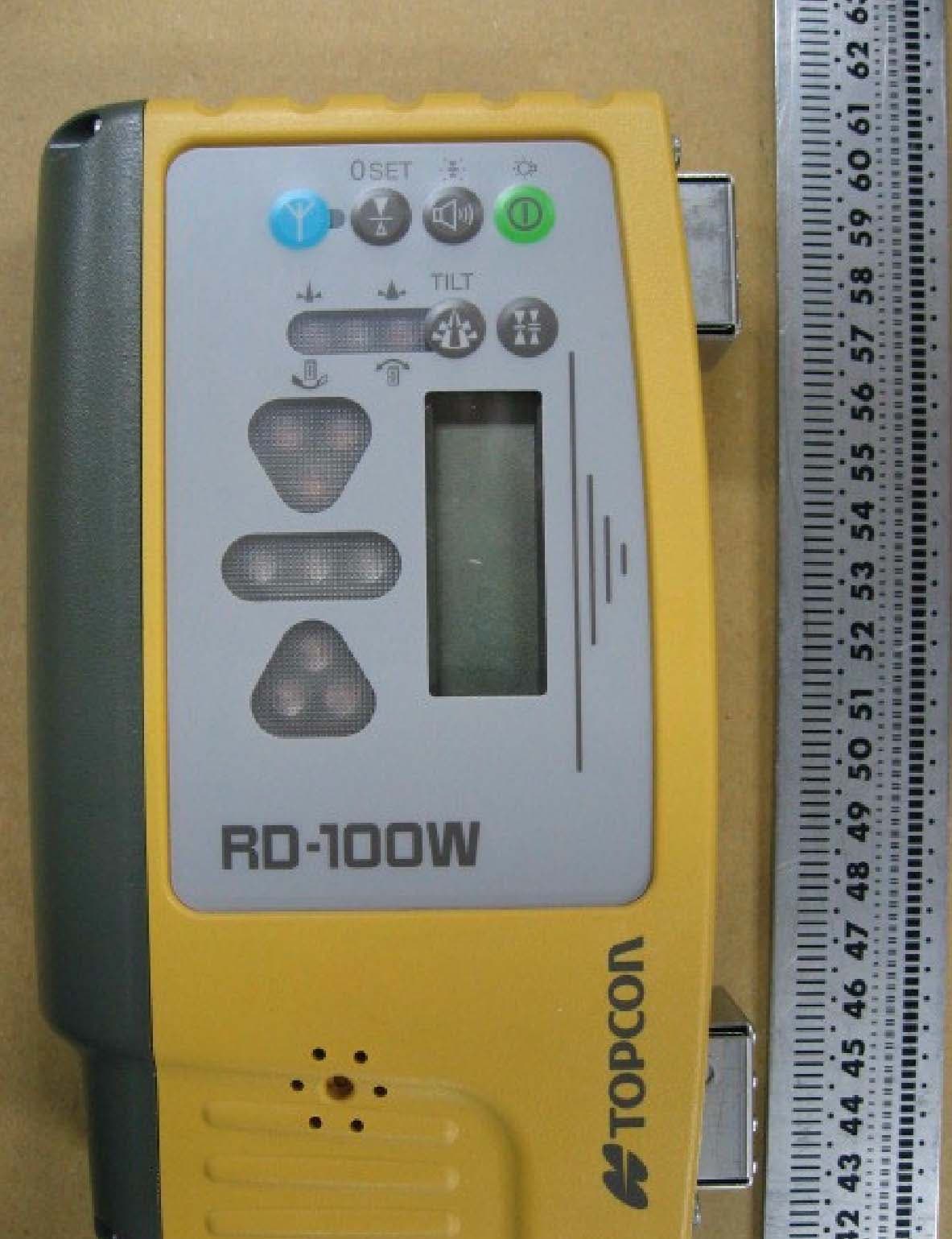
Click to zoom
Application Details
- Equipment Class
- DTS - Digital Transmission System
- Date of Grant
- Mar 26, 2008
- Application Purpose
- Original Equipment
- Date of Application
- Mar 26, 2008
- Equipment Note
- Remote Display
- Frequency Range
- 2405.00000000 - 2475.00000000
- Company
- Topcon Corporation
- Country
- Japan
Documents & Files
Document Text
Text extracted from the exhibit documents filed with the FCC. Open a document above to read the original.
Users Manual
INSTRUCTION MANUAL REMOTE DISPLAY RD-100W Thank you for purchasing the TOPCON RD-100W. For the best performance of the instruments, please read these instruc- tions carefully and keep them in a convenient location for future refer- ence. GENERAL HANDLING PRECAUTIONS Before starting work or operation, be sure to check that the system is functioning properly. Affection of the radio waves When using the instrument in the following place, the strong radio wave may cause faulty operation. •Near the instrument occurring strong radio waves. (e.g. Transceiver) •Near the radio wave towers such as television or radio. DISPLAY FOR SAFE USE In order to encourage the safe use of products and prevent any danger to the operator and others or damage to properties, important warnings are put on the products and inserted in the instruction manuals. We suggest that everyone understand the meaning of the following dis- plays and icons before reading the “Safety Cautions” and text. • Injury refers to hurt, burn, electric shock, etc. • Physical damage refers to extensive damage to buildings or equipment and furniture. HANDLING PRECAUTIONS Guarding the instrument against shock When transporting the instrument, provide some protection to minimize risk of shock. Heavy shock may affect beam accuracy. SAFETY CAUTIONS Standard Set Composition 1 RD-100W Instrument ..................................... 1pc. 2 AA-size dry cells............................................. 3pcs. 3 Instruction manual.......................................... 1pc. DisplayMeaning WARNING Ignoring or disregard of this display may lead to death or serious injury. CAUTION Ignoring or disregard of this display may lead to per- sonal injury or physical damage to the instrument. WARNING • There is a risk of fire, electric shock or physical harm if you attempt to disassemble or repair the instrument yourself. This is only to be carried out by TOPCON or an authorized dealer, only! • Risk of fire or electric shock. Do not use damaged power cable, plug and socket. • Risk of fire or electric shock. Do not use a wet battery. • May ignite explosively. Never use an instrument near flammable gas, liquid matter, and do not use in a coal mine. • Do not hold the RD-100W magnetic clamp near anyone who uses a pace maker or other electronic medical devices. The strong magnetic field can disrupt the normal operation of such devices. • Battery can cause explosion or injury. Do not dispose in fire or heat. • The short circuit of a battery can cause a fire. Do not short circuit battery when storing it. CAUTION Risk of injury to fingers. Do not place fingers on magnet while mounting to equipment. Strong magnetic field. Do not place RD-100W magnetic clamp near any sensitive electronic devices or magnetic storage media such as computer disk. Do not allow skin or clothing to come into contact with acid from the batteries, if this does occur then wash off with copious amounts of water and seek med- ical advice. EXCEPTIONS FROM RESPONSIBILITY 1)The user of this product is expected to follow all operating instructions and make periodic checks of the product’s performance. 2)The manufacturer, or its representatives, assumes no responsibility for results of a faulty or intentional usage or misuse including any direct, indirect, consequential damage, and loss of profits. 3)The manufacturer, or its representatives, assumes no responsibility for consequential damage, and loss of profits by any disaster, (an earthquake, storms, floods etc.). A fire, accident, or an act of a third party and/or a usage any other usual conditions. 4)The manufacturer, or its representatives, assumes no responsibility for any damage, and loss of profits due to a change of data, loss of data, an interruption of business etc., caused by using the product or an unusable product. 5)The manufacturer, or its representatives, assumes no responsibility for any damage, and loss of profits caused by usage except for explained in the user manual. 6)The manufacturer, or its representatives, assumes no responsibility for damage caused by wrong movement, or action due to connecting with other products. Nomenclature and Functions Magnet Indicator(LCD) Power switch Power ON: Short push Power OFF: Long push LCD back light ON/OFF: Short push when power is ON (Auto turn-off after two minutes) Detective precision (Mode) switch Buzzer sound switch Buzzer sound: Quiet/Loud/OFF:Short push LED ON/OFF: Long push Indicator(LED) Buzzer speaker Risk of damage to installation surface of machine, because it uses a strong magnet. See [Laser beam positions and display patterns] in the Instruction manual for the display area and display pattern. This instrument is able to perform wireless communication with the LS-B110W/LS-B10W, sold separately. See the LS-B110W/LS-B10W Instruction manual for details on the LS-B110W/LS-B10W. Wireless communication switch Communication ON/OFF: Short push Communication default setting: Long push Wireless communication LED Tilt switch Zero-set switch Battery cover Battery cover knob How to set up the wireless communication default setting Place the LS-B110W/LS-B10W and RD-100W in close position, so that they will not be affected by other wireless communications. 1Turn on the power for both the LS-B110W/LS-B10W and RD-100W. 2Long-push the wireless communication switch for the LS-B110W/LS-B10W and RD-100W. While setting up, the wireless communi- cation LED (yellow light) will turn on. 3When the instrument is ready to be used, a buzzer will sound (buzzer sound: peep) and the communication will begin. How to use wireless communication 1When power for both the LS-B110W/LS-B10W and RD-100W are turned ON, communication will automatically begin. During communication, the wireless communication LED will flash quickly. During communication preparation, the wireless communication LED will flash slowly Lighting/Flashing pattern of wireless communication LED LightsWhile setting up the default Flashes quickly Whi…
Text truncated - open the document above for the full version.
Cover Letter(s)
TOPCON CORPORATION Declaration March 26, 2008 Federal Communication Commission 7435 Oakland Mills Road Columbia, MD 21046 RE: FCC ID: H5P-RD-100W We, Topcon Corporation Topcon CorporationTopcon Corporation Topcon Corporation, declare that Mr. Fumio Ohtomo gives Mr. Kazuki Osaragi authority to sign the declaration for FCC application of FCC ID: H5P-RD-100W. Fumio Ohtomo Director Senior Managing Executive Officer General Manager
Cover Letter(s)
Letter of Agency March 13, 2008 Federal Communication Commission Equipment Authorization Division Application Processing Branch 7435 Oakland Mills Road Columbia, Maryland 21046 FCC ID: H5P-RD-100W To Whom It May Concern: Please be advised that Topcon Corporation authorizes UL Japan, Inc. to act on our behalf, until otherwise notified, for applications submitted to Federal Communication Commission. We certify that we are not subject to denial of federal benefits, that includes FCC benefits, pursuant to Section 5301 of the Anti-Drug Abuse ACT of 1988, U.S.C. 862. Further, no party, as defined in 47 CFR 1.2002(b), to the application is subject to denial of federal benefits, that includes FCC benefits. The application for the subject equipment has not been submitted to another TCB for certification. Thank you for your attention to this matter. Sincerely, Kazuki Osaragi Senior Manager TOPCON CORPORATION FCC Labeling Requirements and Information March 13, 2008 Federal Communication Commission Equipment Authorization Division Application Processing Branch 7435 Oakland Mills Road Columbia, Maryland 21046 RE: FCC Labeling Requirements FCC ID: H5P-RD-100W The following label information is required by the FCC Rules and Regulations for certified devices. Also attached, please find marketing information required by the FCC Rules and Regulations. Thank you for your attention to these matters. Sincerely, Kazuki Osaragi Senior Manager TOPCON CORPORATION Request for Confidentiality March 13, 2008 Federal Communication Commission Equipment Authorization Division Application Processing Branch 7435 Oakland Mills Road Columbia, Maryland 21046 RE: Certification Application FCC ID: H5P-RD-100W Please be advised that the following information is to be held confidential and behalf of, Top c o n Corporation referring to the FCC rules 0.457 and 0.459: Block Diagram Schematics Theory of Operation Parts List The application contains technical information which Topcon Corporation deems to be trade secrets and proprietary. If made public, the information might be used to the disadvantage of the applicant in the market place. Thank you for your attention to this matter. Sincerely, Kazuki Osaragi Senior Manager TOPCON CORPORATION TOPCON CORPORATION Manufacturer’s Letter March 13, 2008 Federal Communication Commission Equipment Authorization Division Application Processing Branch 7435 Oakland Mills Road Columbia, Maryland 21046 RE: Certification Application FCC ID: H5P-RD-100W To Whom It May Concern: Please be advised that the manufacturer will ensure that the above-referenced model will be manufactured in accordance with the FCC Rules and Regulations. Thank you for your attention to this matter. Sincerely, Kazuki Osaragi Senior Manager
Internal Photos
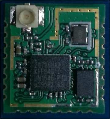
Radio Module
RF Exposure Info
UL Japan, Inc. YAMAKITA EMC LAB. 907 Kawanishi, Yamakita-machi, Ashigarakami-gun, Kanagawa-ken, 258-0124 JAPAN Telephone: +81 465 77 1011 Facsimile: +81 465 77 2112 Applicant: TOPCON Corporation Type of Equipment : Remote Display M odel No. : RD-100W FCC ID: H5P-RD-100W TOPCON Corporation declares that M odel : Remote Display complies with FCC radiation exposure requirement specified in the FCC Rules 2.1091. The “H5P-RD-100W“ has 1.26 mW of conducted Peak Output power and 1.83 mW of EIRP. This equipment is considered as a mobile device so that SAR testing is excluded. The Following calculation is the reference data for 20cm distance. RF Exposure Calculations: The following information provides the minimum separation distance for the highest gain antenna provided with the “H5P-RD-100W“ as calculated from FCC OET Bulletin 65 Appendix A, Table (B) Limits for General Population / Uncontrolled Exposure. This calculation is based on the highest EIRP possible from the system, considering maximum power and antenna gain, and considering a 1.0mW/cm^2 uncontrolled exp o su re lim it. T he F riis fo rm u la u sed w as: S = (P * G) / (4* π * r 2 ) Where P = 1.26 mW (M aximum peak output power) G = 1.46 Numerical Antenna gain; equal 1.64 dBi r =20.0 cm For: RD-100WS = 0.00036 mW/cm 2 No. : 28CE0167-YK-G RF Exposure Statement
Test Report
FCC ID : H5P-RD-100W Test report No. : 28CE0167-YK-G Page : 2 of 34 Issued date : February 13, 2008 UL Japan, Inc. YAMAKITA EMC LAB. 907 Kawanishi, Yamakita-machi, Ashigarakami-gun, Kanagawa-ken, 258-0124 JAPAN Telephone: +81 465 77 1011 Facsimile: +81 465 77 2112 MF060b (09.01.08) Table of Contents Page 1 Applicant Information 3 2 Equipment under test (E.U.T.) 3 3 Test Specification, Procedures and Results 4 4 System Test Configuration 6 5 6dB Bandwidth & Occupied Bandwidth (99%) 7 6 Maximum Peak Output Power 7 7 Out of Band Emissions (Antenna Port Conducted) 7 8 Out of Band Emissions (Radiated) 8 9 Peak Power Density 9 Contents of Appendixes 10 APPENDIX 1: Photographs of test setup 11 APPENDIX 2: Test Data 12 APPENDIX 3: Test instruments 33 APPENDIX 4: Duty factor calculation and Transmitting time and interval 34 FCC ID : H5P-RD-100W Test report No. : 28CE0167-YK-G Page : 3 of 34 Issued date : February 13, 2008 UL Japan, Inc. YAMAKITA EMC LAB. 907 Kawanishi, Yamakita-machi, Ashigarakami-gun, Kanagawa-ken, 258-0124 JAPAN Telephone: +81 465 77 1011 Facsimile: +81 465 77 2112 MF060b (09.01.08) 1 Applicant Information Company Name : TOPCON Corporation Brand or Trade name : TOPCON Address : 75-1 Hasunuma-cho, Itabashi-ku, Tokyo-to, 174-8580 Japan Telephone Number : +81-3-3558-2577 Facsimile Number : +81-3-3966-0038 Contact Person : Yasutake Katayama 2 Equipment under test (E.U.T.) 2.1 Identification of E.U.T. Type of Equipment : Remote Display Model No. : RD-100W Serial No. : Refer to SECTION 4 in this report. Rating : DC4.5V (3 pieces of AA type battery operation) Country of Manufacture : Japan Receipt Date of Sample : November 26, 2007 Condition of EUT : Production prototype (Not for Sale: This sample is equivalent to mass-produced items.) 2.2 Product Description Model No: RD-100W (referred to as the EUT in this report) is a Remote Display. Clock frequencies : 4.9152MHz Equipment type : Transceiver Radio Specification Frequency band : Lower limit 2405MHz Upper limit 2480MHz Bandwidth & channel spacing : 80MHz & 5MHz Type of modulation : DSSS Antenna type : Ceramic chip antenna Antenna connector type : N/A Antenna gain : +1.64dBi ITU code : F1D Operating voltage (Inner) : DC3.3V Operation temperature range : -20 to +60 deg.C. FCC 15.31 (e) The TOPCON product provides stable voltage (DC3.3V) constantly to the EUT (RF Module) regardless of input voltage. Therefore, the EUT complies with the requirement. FCC Part 15.203 The antenna is not removable from the EUT. Therefore, the equipment complies with the antenna requirement of Section 15.203. FCC ID : H5P-RD-100W Test report No. : 28CE0167-YK-G Page : 4 of 34 Issued date : February 13, 2008 UL Japan, Inc. YAMAKITA EMC LAB. 907 Kawanishi, Yamakita-machi, Ashigarakami-gun, Kanagawa-ken, 258-0124 JAPAN Telephone: +81 465 77 1011 Facsimile: +81 465 77 2112 MF060b (09.01.08) 3 Test Specification, Procedures and Results 3.1 Test specification Test specification : FCC Part15 Subpart C: 2008, final revised on January 30, 2008 Title : FCC 47CFR Part15 Radio Frequency Device Subpart C Intentional Radiators Section 15.207 Conducted limits Section 15.209 Radiated emission limits, general requirements Section 15.247 Operation within the bands 902-928MHz, 2400-2483.5MHz, and 5725-5850MHz *The revision on January 30, 2008 does not influence the test specification applied to the EUT. 3.2 Procedures & Results Item Test Procedure Specification RemarksDeviationWorst Margin Results Conducted Emission ANSI C63.4:2003 7. AC powerline conducted emission measurements FCC 15.207 - N/A *1 - N/A 6dB Bandwidth FCC Public Notice Guidance on Measurement for Digital Transmission Systems Section15.247 FCC 15.247 (a)(2) & 15.209 ConductedN/A Complied Maximum Peak Output Power FCC Public Notice Guidance on Measurement for Digital Transmission Systems Section15.247 FCC 15.247 (b)(3) & 15.209 ConductedN/A - Complied Out of Band Emission & Restricted Band Edges FCC Public Notice Guidance on Measurement for Digital Transmission Systems Section15.247 15.247 (d) & 15.209 Conducted / Radiated N/A Tx: 1.7dB (2483.50MHz, Vertical, PK, Tx 2480MHz) Complied Power Density FCC Public Notice Guidance on Measurement for Digital Transmission Systems Section15.247 FCC 15.247 (e) & 15.209 ConductedN/A - Complied Note: UL Japan’s EMI Work Procedures No.QPM05 and QPM15. *1) The test is not applicable since the EUT does not have AC Mains. 3.3 Addition to standard Item Test Procedure Specification Remarks Worst Margin Results Occupied Bandwidth (99%) ANSI C63.4:2003 13. Measurement of intentional radiators RSS-Gen 4.6.1 RSS-Gen 4.6.1 Conducted - Complied * Other than above, no addition, exclusion nor deviation has been made from the standard. FCC ID : H5P-RD-100W Test report No. : 28CE0167-YK-G Page : 5 of 34 Issued date : February 13, 2008 UL Japan, Inc. YAMAKITA EMC LAB. 907 Kawanishi, Yamakita-machi, Ashigarakami-gun, Kanagawa-ken, 258-0124 JAPAN Telephone: +81 465 77 1011 Facsimile: +81 465 77 2112 MF060b (09.01.08) 3.3 Uncertainty The following uncertainties have been calculated to provide a confidence level of 95% using a coverage factor k=2. No.1 open site (±) No.2 open site (±) No.1 anechoic chamber (±) Radiated emission (3m) 30-300MHz 4.5 dB 4.4 dB 4.5 dB 300-1000MHz 4.3 dB 4.3 dB 4.3 dB 1GHz< 5.7 dB 5.7 dB 5.7 dB Antenna port conducted test ( ± ) Below 1GHz 0.4dB 1GHz and above 0.7dB Radiated Emission Test The data listed in this report meets the limits unless the uncertainty is taken into consideration. 3.4 Test Location UL Japan, Inc. Yamakita EMC Lab. 907, Kawanishi, Yamakita-machi, Ashigarakami-gun, Kanagawa-ken 258-0124 JAPAN Telephone number : +81 465 77 1011 Facsimile number : +81 465 77 2112 NVLAP Lab. code : 200441-0 No. 1 test site has been fully described in a report submitted to FCC office, and accepted on August 26, 2005 (Registration No.: 95486). IC Registration No. : 2973B-1 No. 2 test site has been fully described in a report submitted to FCC office, and accepted on April…
Text truncated - open the document above for the full version.
Test Setup Photos
FCC ID : H5P-RD-100W Test report No. : 28CE0167-YK-G Page : 11 of 34 Issued date : February 13, 2008 UL Japan, Inc. YAMAKITA EMC LAB. 907 Kawanishi, Yamakita-machi, Ashigarakami-gun, Kanagawa-ken, 258-0124 JAPAN Telephone: +81 465 77 1011 Facsimile: +81 465 77 2112 MF060b (09.01.08) Radiated emission FCC ID : H5P-RD-100W Test report No. : 28CE0167-YK-G Page : 12 of 34 Issued date : February 13, 2008 UL Japan, Inc. YAMAKITA EMC LAB. 907 Kawanishi, Yamakita-machi, Ashigarakami-gun, Kanagawa-ken, 258-0124 JAPAN Telephone: +81 465 77 1011 Facsimile: +81 465 77 2112 MF060b (09.01.08) Pre-check of the worst position X-axis Y-axis Z-axis
Contact Information
Applicant
Kazuki Osaragi(Senior Manager)
Technical Contact
UL Japan, Inc.Tatsuya Arai
[email protected]+81-465-77-1011
907 Kawanishi, Yamakita-machi, Ashigarakami-gun · Kanagawa-ken · Japan
Non-Technical Contact
UL Japan, Inc.Yoshinobu Asai
[email protected]+81-596-24-8116
Test Firm
UL Japan, Inc. Yamakita EMC Lab.Tetsuya Hashimoto
Technical Specifications
| # | Rule Parts | Frequency Range | Power Output |
|---|---|---|---|
| 1 | 15C | 2.40 GHz - 2.48 GHz | 1.26 mW |
Other Applications from Topcon Corporation
H5P-333047
Oct 27, 2020Bluetooth module
Equipment Class
DSS - Part 15 Spread Spectrum Transmitter
H5P-RLSV
Jun 29, 2011Rotating Laser
Equipment Class
DSS - Part 15 Spread Spectrum Transmitter
H5P-RF10
Jun 29, 20112.4GHz BAND DATA COMMUNICATION MODULE
Equipment Class
DSS - Part 15 Spread Spectrum Transmitter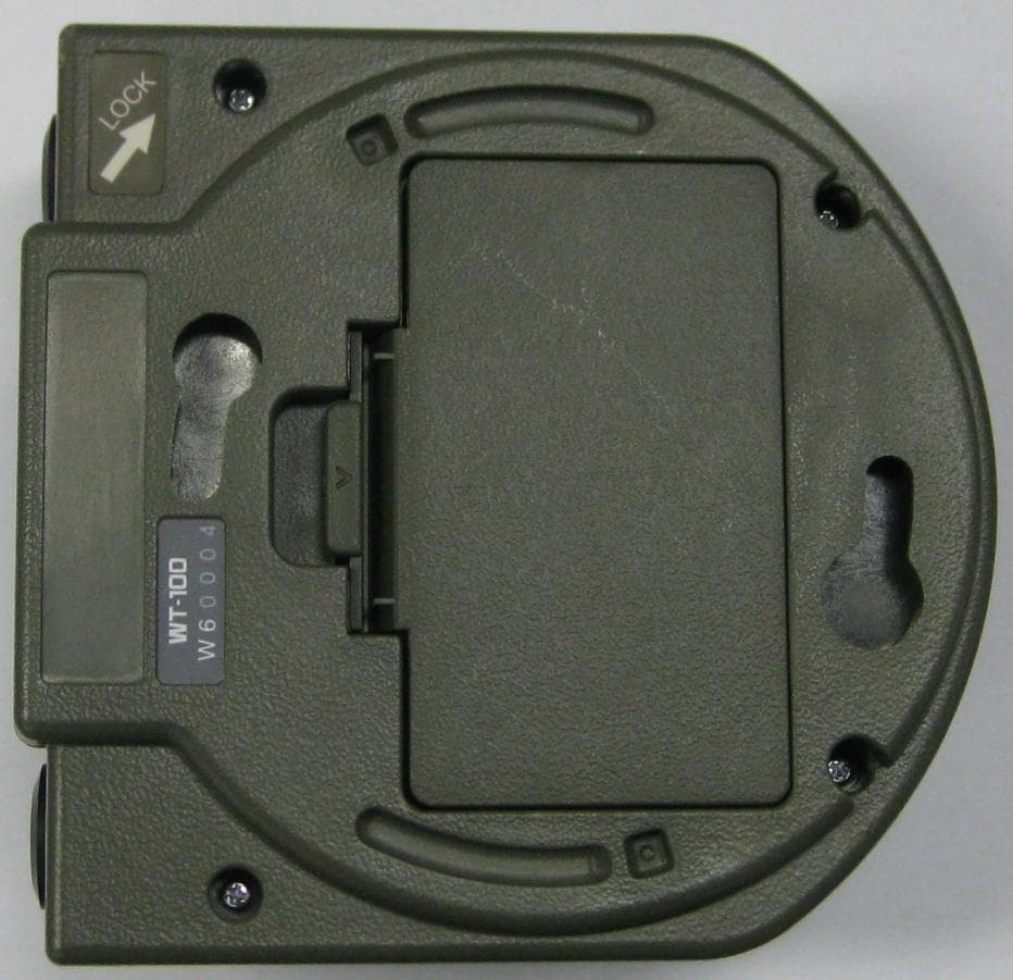
H5P-WT100
Feb 20, 2011Wireless Terminal
Equipment Class
DTS - Digital Transmission System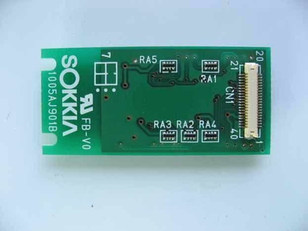
H5P-WT11EC
Dec 21, 2009Bluetooth Module
Equipment Class
DSS - Part 15 Spread Spectrum Transmitter