H5PRC-30Remote Controller
Topcon Corporation
Click to zoom
Application Details
- Equipment Class
- DSC - Part 15 Security/Remote Control Transmitter
- Date of Grant
- Nov 17, 2005
- Application Purpose
- Original Equipment
- Date of Application
- Nov 17, 2005
- Equipment Note
- Remote Controller
- Frequency Range
- 429.25000000 - 429.73750000
- Company
- Topcon Corporation
- Country
- Japan
Documents & Files
Document Text
Text extracted from the exhibit documents filed with the FCC. Open a document above to read the original.
Users Manual
INSTRUCTION MANUAL RC-30 Remote Control for RL-VH3 series lasers Foreword Thank you for purchasing the TOPCON RC-30 Remote Control. For the best performance of the instruments, please read these instruc- tions carefully and keep them in a convenient location for future refer- ence. Handling Precautions Vibration and Impact Protection When transporting the instrument, provide protection to minimize risk of severe vibration or impact. Display for Safe Use In order to encourage the safe use of products and prevent any danger to the operator and others or damage to properties, important warnings are put on the products and inserted in the instruction manuals. We suggest that everyone understand the meaning of the following dis- plays and icons before reading the “Safety Cautions” and text. 1) Injury refers to hurt, burn, electric shock, etc. 2) Physical damage refers to extensive damage to buildings or equipment and furniture. Safety Cautions Specifications Functions Function Descriptions How to Set Communication Channel The same communication channel must be assigned to both the RC-30 and the RL-VH3 series laser instrument. Remove the rubber cap and turn the rotary switch to set a channel. Refer to the your RL-VH3 laser operating manual for instructions on setting the same com- munications channel on the laser instru- ment. How to Replace the RC-30 Batteries 1Remove the battery cover from the back of the RC-30 by pressing on the cover and sliding it in the direction of the arrow. 2Remove the old batteries and replace with new three “AA” cell alkaline batteries making sure each is placed in the proper direction as indicated. 3Replace the battery cover. You will hear a click when it snaps in place. DisplayMeaning WARNING Ignoring or disregard of this display may lead to death or serious injury. CAUTION Ignoring or disregard of this display may lead to personal injury or physical damage to the instrument. WARNING • There is a risk of fire, electric shock or physical harm if you at- tempt to disassemble or repair the instrument yourself. This is only to be carried out by TOPCON or an authorized dealer, only! • Risk of fire or electric shock. Do not use a wet battery or charger. • May ignite explosively. Never use an instrument near flammable gas, liquid matter, and do not use in a coal mine. • Battery can cause explosion or injury. Do not dispose in fire or heat. • The short circuit of a battery can cause a fire. Do not short circuit battery when storing it. CAUTION Do not allow skin or clothing to come into contact with acid from the bat- teries, if this does occur then wash off with copious amounts of water and seek medical advice. Power source Three “AA” cell batteries DC4.5V Operating time Alkaline manganese dry batteries Approx. 3 month ( +20°C) Operating temperature -20°C to +50°C (-4°F to +122°F) Dimensions 157(L) x 64(W) x 34(H) mm (6.2 (L) x2.5 (W) x 1.3(H) ) in Weight 0.24kg (0.05 lbs) Changes or modifications not expressly approved by the party responsible for compliance could void the user’s authority to operate the equipment. Operation is subject to the following two conditions: (1) this device may not cause interference, and (2) this device must accept any interference received, including interference that may cause undesired operation of the device. Lutilisation de ce dispositif est autorisee seulement aux conditions suivantes : (1)il ne doit pas produire de brouillage et (2)l’utilisateur du dispositif doit être prêt à accepter tout brouillage radioelectrique recu,même si ce brouillage est sus- ceptible de compromettre le fonctionnement du dispositif. This Class B digital apparatus complies with Canadian ICES-003. Cet apparei numerique de la class B est conforme à la norme NMB-003 du Can- ada. FCC WARNING Laser power switch (Standby mode) Pressing for more than three seconds turns laser standby mode on or off. Laser turns off if standby mode continues for two hours. Transmission lamp This lamp will light when a key of RC-30 is pressed. Battery warning lamp for RC-30 Battery warning for RC-30. Replace the batteries with new ones when lit. Stop beam control Sets Stop Beam mode and moves the laser. (RL-VH3G/A/B models only) Speed control The rotation speed of the rotary head can be changed. Alignment control Moves beam up or down (horizontal rotation). Moves beam right or left (vertical rotation). X/Y axis lamp Indicates axis selected during beam sloping. Mode switch con- trol Laser mode is switched alternately as follows. Scan mode / Laser sensor mode / Laser pointing mode. If this key is pressed in other modes except Scan, Laser sensor and Laser pointing modes, the mode will change to scan mode. If this key is pressed in manual focus mode, manual focus will be cancelled. (RL-VH3G/A models only) Manual focus con- trol Laser beam can be focused manually. (RL-VH3G/A models only) X/Y axis selection Vertical: Setting alignment control Horizontal: Setting slope Sets alignment control mode by pressing the key for more than three seconds. Then X axis lamp will light. Sets slope mode by pressing the key for more than three seconds. Then X lamp will light. Select X or Y axis for manual grading. To cancel the slope or alignment control mode press this key for more than three seconds. Note • Replace all 3 batteries with new ones. • Do not mix old batteries and new ones. Battery warning lamp for RC-30 Transmission lamp Laser power switch (Standby mode) Mode switch control (RL-VH3G does not have Laser sensor mode.) Slope mode / X/Y axis selection X/Y axis lamp Alignment control Speed control Manual focus control (RL-VH3G/A models only) Stop beam control (RL-VH3G/A/B models only) Rotary switch (with rubber cap) Battery cover RC-30 31325 91580 (TPS)
Attestation Statements
Akzo Nobel K. K. EMC Division Bancho Kaikan 12-1, Gobancho, Chiyoda-ku Tokyo 102-0076 Japan Tel.+81 3 5210 5411 Fax.+81 3 5216 2860 October 28, 2005 Federal Communications Commission Office of Engineering and Technology 7435 Oakland Mills Road Columbia, MD 21046 RE: LETTER OF AGENT AUTHORIZATION To Whom It May Concern: We, the undersigned, hereby authorize PCTEST Engineering Laboratory, Inc. to act on our behalf in all matters relating to application for equipment authorization, including the signing of all documents relating to these matters. We also hereby certify that no party to the application authorized hereunder is subject to the denial of benefits, including FCC benefits, pursuant to Section 5301 of the Anti-Drug Abuse Act of 1988,21 U.S.C.862. This authorization expires one year from the current date. Sincerely, Akzo Nobel K. K. Junichi Okada Group Leader Technology Management Group EMC Division
ID Label/Location Info
FCC and IC PRODUCT LABELING Location of labels on EUT FCC DoC Label FCC ID and IC code
Test Report
Report No. ANKK –105261 FCC ID : H5PRC-30 IC CN and UPN : 6050A-RC30 © Akzo Nobel K. K. EMC Div. Page 1 of 38 Version 6.5 CERTIFICATE OF COMPLIANCE Regulation : FCC Part15C(Section 15.231) RSS-210 issue 6(Section A.1.1) Applicant Testing Laboratory TOPCON CORPORATION 75-1, Husunuma-cho, Itabashi-ku, Tokyo, 174-8580 Japan Tel : +81 3 3558 2576 Fax : +81 3 3966 0038 Akzo Nobel K. K. Kashima site 1, Sunayama, Kamisu-shi Ibaraki-ken 314-0255 Japan Tel.: +81 479 40 1097 Fax.: +81 479 46 1788 E-mail: [email protected] URL: http://www.akzoemc.co.jp Equipment Type Remote Controller Trademark TOPCON Model (s) RC-30 Serial No. 3K0001 Equipment Authorization Certification (FCC ID : H5PRC-30, IC CN and UPN : 6050A-RC30) Test Result Complied Report Number ANKK-105261 Report Issue Date November 1, 2005 This equipment has been shown to be capable of compliance with the applicable standard(s) as indicated in the test report. I attest to the accuracy of data. All measurements reported herein were performed by me or were made under my supervision and are correct to the best of my knowledge and belief. I assume full responsibility for the completeness of these measurements and vouch for the qualifications of all persons taking them. This test report shall not be reproduced partially, or in full, without the prior written approval of Akzo Nobel K.K. The results and statements contained in this report pertain only to the equipment evaluated. Approved by Tested by Gokita Kazuo [ Assistant Manager ] Naoki Ikeda Katsuya Uchida Responsible Party of Test Item (Product) Responsible Party : Add. : Tel. : Fax. : Contact Person : This report contains data that are not covered by the NVLAP accreditation. Lab Code 100290-3 Report No. ANKK –105261 FCC ID : H5PRC-30 IC CN and UPN : 6050A-RC30 © Akzo Nobel K. K. EMC Div. Page 2 of 38 Version 6.5 TABLE OF CONTENTS Page SECTION 1. GENERAL INFORMATION ........................................................................................................... 3 SECTION 2. SUMMARY OF TEST RESULTS ...................................................................................................4 SECTION 3. INFORMATION ABOUT EUT ....................................................................................................... 5 SECTION 4. SUPPORT EQUIPMENT(S) ............................................................................................................ 6 SECTION 5. USED CABLE (S)............................................................................................................................ 7 SECTION 6. PHOTOGRAPHS OF MAXIMUM EMISSION SET-UP................................................................ 8 SECTION 7. OPERATING CONDITION........................................................................................................... 11 SECTION 8. TEST PROCEDURE(S) ................................................................................................................. 12 SECTION 9. EVALUATION OF TEST RESULTS............................................................................................. 14 SECTION 10. LIST OF MEASURING INSTRUMENTS .................................................................................... 36 SECTION 11. MEASUREMENT UNCERTAINTY ............................................................................................. 37 SECTION 12. DESCRIPTION OF TEST LABORATORY .................................................................................. 38 Report No. ANKK –105261 FCC ID : H5PRC-30 IC CN and UPN : 6050A-RC30 © Akzo Nobel K. K. EMC Div. Page 3 of 38 Version 6.5 SECTION 1. GENERAL INFORMATION TEST PERFORMED Location Kashima No.1 Test Site EUT Received October 20, 2005 Te s t St a r t e d October 20, 2005 Te s t C o m p l e t e d October 27, 2005 Standard Applied FCC Part15C(Section 15.231) , RSS-210(Section A1.1) Unintentional Radiators Test Setup ANSI C63.4-2003 Deviation from Standard (s) No deviation TEST TRACEABILITY Traceability to national standards of test result is achieved by means of calibration traceability to national or international standards. LIMITATIONS ON RESULTS The test result of this report is effective for equipment under test itself and under the test configuration described on the report. This test report does not assure that whether the test result taken in other testing laboratory is compatible or reproducible to the test result on this report or not. ABBREVIATIONS AE = Associated Equipment DIP = Dipole Antenna AMN = Artificial Mains Network DoC = Device for Declaration of Conformity AMP = Amplifier, ATT = Attenuato r EUT = Equipment Under Test ANT = Antenna, BBA = Broadband Antenna ISN = Impedance Stabilization Network AVG = Average LISN = Line Impedance Stabilization Network Cal = Calibration PK = Peak CDN = Coupling Decoupling Network Q-P = Quasi-peak Report No. ANKK –105261 FCC ID : H5PRC-30 IC CN and UPN : 6050A-RC30 © Akzo Nobel K. K. EMC Div. Page 4 of 38 Version 6.5 SECTION 2. SUMMARY OF TEST RESULTS This test report clearly shows that the EUT is in compliance with the FCC Part15C(Section15.231) , RSS-210(SectionA1.1) specification. The minimum margins to the limits are as follows: Transmitter Requirement Reference of FCC Reference of RSS-210 Result Radiated ( Fundamental ) Section 15.231(b) A1.1.2 Pass *Note c: Horizontal Transmitter Time Section 15.231(a)(1) A1.1.1(2) Pass Radiated ( Spurious ) Section 15.231(b) A1.1.2 Pass *Note b *Note c: Vertical Restricted bands of operation Section 15.231(b) Section 15.205 Section 15.209 A1.1.2 Pass *Note c: Horizontal Emission Bandwidth (20dB and 26dB) Section 15.231(c) A1.1.3 Pass *Note c: Horizontal Note a : See Section 9 for details. Note b : We evaluated spurious levels with the limit value of FCC Section 15.209. Spurious levels are satisfied with also Section 15.231(b). Note c : Tested both Horizontal Condition and Vertical Condition. For the results in the worst condition , see above. < Sample Calcul…
Text truncated - open the document above for the full version.
Test Setup Photos
Report No. ANKK –105261 FCC ID : H5PRC-30 IC CN and UPN : 6050A-RC30 © Akzo Nobel K. K. EMC Div. Page 1 of 3 Version 6.5 APPENDIX Report No. ANKK –105261 FCC ID : H5PRC-30 IC CN and UPN : 6050A-RC30 © Akzo Nobel K. K. EMC Div. Page 2 of 3 Version 6.5 PHOTOGRAPHS OF MAXIMUM EMISSION SET-UP Radiated Electric Field (Horizontal Condition) Report No. ANKK –105261 FCC ID : H5PRC-30 IC CN and UPN : 6050A-RC30 © Akzo Nobel K. K. EMC Div. Page 3 of 3 Version 6.5 Radiated Electric Field (Vertical Condition)
Contact Information
Applicant
Kazuki Osaragi(Senior Manager)
Technical Contact
PCTEST Engineering Laboratory, Inc.Randy Ortanez
[email protected]410-290-6652
6660-B Dobbin Road · Columbia, Maryland · United States
Test Firm
Akzo Nobel K.K.Shuichi Kobayashi
Technical Specifications
| # | Rule Parts | Frequency Range | Power Output |
|---|---|---|---|
| 1 | 15.231 | 429.25 MHz - 429.7375 MHz | - |
Other Applications from Topcon Corporation
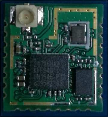
H5P-333047
Oct 27, 2020Bluetooth module
Equipment Class
DSS - Part 15 Spread Spectrum Transmitter
H5P-RLSV
Jun 29, 2011Rotating Laser
Equipment Class
DSS - Part 15 Spread Spectrum Transmitter
H5P-RF10
Jun 29, 20112.4GHz BAND DATA COMMUNICATION MODULE
Equipment Class
DSS - Part 15 Spread Spectrum Transmitter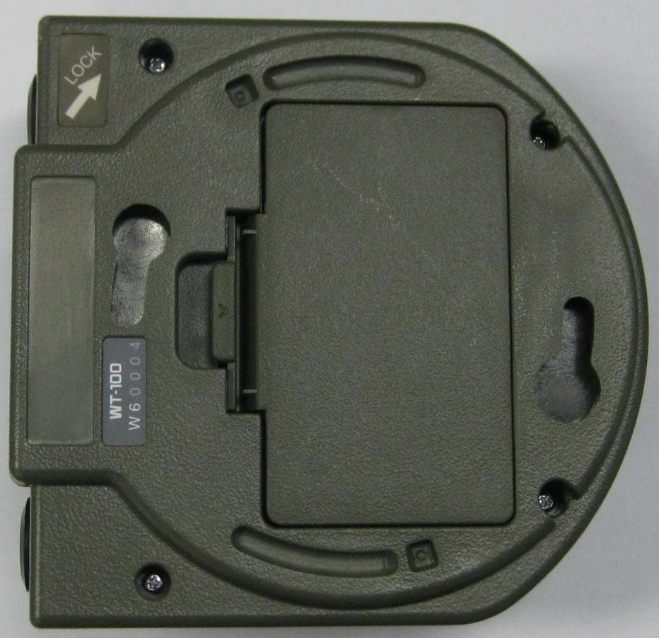
H5P-WT100
Feb 20, 2011Wireless Terminal
Equipment Class
DTS - Digital Transmission System
H5P-WT11EC
Dec 21, 2009Bluetooth Module
Equipment Class
DSS - Part 15 Spread Spectrum Transmitter