H6M-LNKC1900LNKC1900
Powerwave Technologies Inc.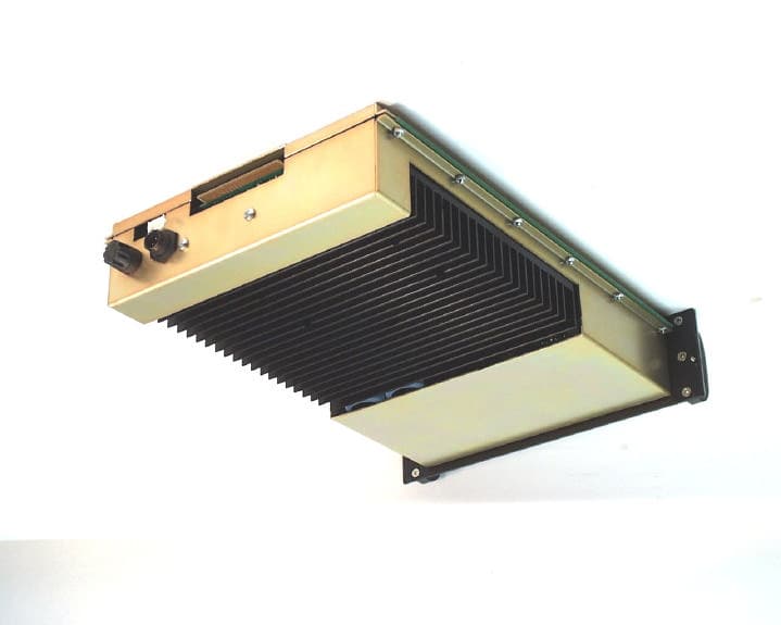
Click to zoom
Application Details
- Equipment Class
- AMP - Amplifier
- Date of Grant
- Oct 18, 2001
- Application Purpose
- Original Equipment
- Date of Application
- Jul 08, 2001
- Equipment Note
- LNKC1900
- Frequency Range
- 1930.00000000 - 1990.00000000
- Company
- Powerwave Technologies Inc.
- Country
- United States
Documents & Files
Document Text
Text extracted from the exhibit documents filed with the FCC. Open a document above to read the original.
Users Manual
LinkNetô LinkNetôLinkNetô LinkNetô LNKC1900 RF 1900MHz PCS MODULES LNKC1900 RF 1900MHz PCS MODULESLNKC1900 RF 1900MHz PCS MODULES LNKC1900 RF 1900MHz PCS MODULES USER MANUAL USER MANUALUSER MANUAL USER MANUAL INSTALLATION, OPERATION INSTALLATION, OPERATIONINSTALLATION, OPERATION INSTALLATION, OPERATION AND MAINTENANCE AND MAINTENANCEAND MAINTENANCE AND MAINTENANCE KAVAL WIRELESS TECHNOLOGIES 60 Gough Road Markham, Ontario, L3R 8X7 Telephone: (888) 86-KAVAL Web: www.kaval.com E-mail: [email protected] Document #DCM000000053, Rev.2 May 30, 2001 LinkNetô LNKC1900 RF MODULES ! USER MANUAL DCM000000053 Printed: 2001-05-30 10:37:48 Revision Date: 5/30/01: ii P PP P P PP P R RR R R RR R O OO O O OO O P PP P P PP P R RR R R RR R I II I I II I E EE E E EE E T TT T T TT T A AA A A AA A R RR R R RR R Y YY Y Y YY Y S SS S S SS S T TT T T TT T A AA A A AA A T TT T T TT T E EE E E EE E M MM M M MM M E EE E E EE E N NN N N NN N T TT T T TT T © 2000 KAVAL WIRELESS TECHNOLOGIES All rights reserved. No part of this publication, or any software included with it may be reproduced, stored in a retrieval system, or transmitted in any form or by any means, including photocopying, electronic, mechanical, recording or otherwise, without the prior written permission of the copyright holder. This document contains proprietary information of KAVAL WIRELESS TECHNOLOGIES The contents are confidential and any disclosure to persons other than the officers, employees, agents or subcontractors of the owner or licensee of this document, without the prior written consent of KAVAL WIRELESS TECHNOLOGIES, is strictly prohibited. KAVAL WIRELESS TECHNOLOGIES provides this document as is, without any warranty of any kind either expressed or implied including, but not limited to, the implied warranties of merchantability and fitness of a particular purpose. KAVAL WIRELESS TECHNOLOGIES may make changes or improvements in the equipment, software, or specifications described in this document at any time and without notice. These changes will be incorporated in new releases of this document. This document may contain technical inaccuracies or typographical errors. KAVAL WIRELESS TECHNOLOGIES waives responsibility for any labour, materials, or costs incurred by any person or party as a result of using this document. KAVAL WIRELESS TECHNOLOGIES, and any of its affiliates shall not be liable for any damages (including, but not limited to, consequential, indirect or incidental, special damages or loss of profits or date) even if they were foreseeable and KAVAL WIRELESS TECHNOLOGIES has been informed of their potential occurrence, arising out of or in connection with this document or its use. T TT T T TT T R RR R R RR R A AA A A AA A D DD D D DD D E EE E E EE E M MM M M MM M A AA A A AA A R RR R R RR R K KK K K KK K N NN N N NN N O OO O O OO O T TT T T TT T I II I I II I C CC C C CC C E EE E E EE E This manual makes reference to trademarks that are the property of other companies. References are used only to refer to the products or services of the trademark owners. LinkNetô is a trademark of KAVAL WIRELESS TECHNOLOGIES LinkNetô LNKC1900 RF MODULES ! USER MANUAL DCM000000053 Printed: 2001-05-30 10:37:48 Revision Date: 5/30/01: iii TABLE OF TABLE OF TABLE OF TABLE OF CONTENTS CONTENTSCONTENTS CONTENTS 1. LNKC1900 MODULES.............................. 4 OVERVIEW.............................................................. 4 Theory Of Operation ......................................... 4 MODELS................................................................. 4 BLOCK DIAGRAM..................................................... 5 LNKC1900 RF Module...................................... 5 MODULE SPECIFICATIONS....................................... 6 OPERATION............................................................ 7 Software Set-up ................................................ 7 Configuration..................................................... 7 Recommended De-Rating Chart ...................... 8 Power On Self Test (POST).............................. 8 Normal Operation.............................................. 9 LINKNET CDMA PCS MODULE Module ....... 10 ANTENNA INSTALLATION........................................ 11 LinkNetô LNKC1900 RF MODULES ! USER MANUAL DCM000000053 Printed: 01.05.30,10:37 Revision Date:5/30/01 4 Theory Of Operation A LINKNET CDMA PCS MODULE is a banded repeater amplifier. The most common LINKNET CDMA PCS MODULE applications are the extension of above ground signals into buildings, tunnels, vehicles or the extension of radio coverage patterns into outdoor shaded areas such as deep valleys. From an applications standpoint, an LINKNET CDMA PCS MODULE is very similar to a regular two-way radio repeater. On Frequency Radio Repeaters can be combined using regular two-way radio multicoupling or duplexing equipment and have input and output signal characteristics to those of regular transmitters and receivers. The one special consideration in LINKNET CDMA PCS MODULE systems is that of input to output antenna isolation. This must be carefully engineered for each installation. The Modules are designed for indoor use only and are intended for mounting in a standard EIA 19 inch rack. Modular design of LINKNET CDMA PCS MODULE circuitry allows for easy servicing, stocking of spares, adaptability and upgrade ability. LNKC1900 MODULE FAMILY MODEL TYPE FREQUENCY LNKC1900-D DownLink 1.25MHz BandWidth 1930 to 1990 MHz LNKC1900-D5 DownLink 5MHz BandWidth 1930 to 1990 MHz LNKC1900-D15 DownLink 15MHz BandWidth 1930 to 1990 MHz LNKC1900-U UpLink 1.25MHz BandWidth 1850 to 1910 MHz LNKC1900-U5 UpLink 5MHz BandWidth 1850 to 1910 MHz LNKC1900-U15 UpLink 15MHz BandWidth 1850 to 1910 MHz 1. LNKC1900 MODULES Overview Models LinkNetô LNKC1900 RF MODULES ! USER MANUAL DCM000000053 Printed: 01.05.30,10:37 Revision Date:5/30/01 5 LNKC1900 RF Module Block diagram Transmit Board UMC Controller Board with TCXO Receive Board IF Board RF Input 1.8…
Text truncated - open the document above for the full version.
Cover Letter(s)
! Page 1 60 Gough Rd., Markham, Ontario, L3R8X7 www.kaval.com, 905-940-3860, 905-946-3003 FAX September 19, 2001 Federal Communications Commission Equipment Authorization Branch 7435 Oakland Mills Rd. Columbia, MD, 21046, USA Subject: CONFIDENTIALTY REQUEST Dear Sir or Madam; Kaval Wireless Technologies respectfully requests confidentiality of certain materials provided with the submission of the LINKnet LNKC1900 under FCC ID: H6M-LNKC1900 in accordance with FCC Regulations 0.459. The confidentiality request applies to the schematic diagrams, SCH000000028, SCH000000041, SCH000000042 and SCH000000043, and all related Parts Lists contained in Exhibit 2. The LINKnet LNKC1900 has been developed at considerable effort and expense by Kaval Wireless Technologies. These items are considered as Trade Secrets and therefore public access to the proprietary material could possibly result in duplication of equipment that could severely damage the companyís business advantage. I appreciate your assistance in this manner. Yours sincerely, Name: Alan C. Aslett, P.Eng. Signature: _________________________________ Title: Director of Engineering - Product Development Date: September 19, 2001
External Photos
ANNEX 3A - EXTERNAL PHOTOGRAPHSPLOT # 1 ANNEX 3A - EXTERNAL PHOTOGRAPHSPLOT # 2 ANNEX 3A - EXTERNAL PHOTOGRAPHSPLOT # 3 KAVAL PCS 1900 MHz BI-DIRECTIONAL AMPLIFIER MODULE, MODEL LNKC1900 ANNEX 3A - EXTERNAL PHOTOGRAPHSPLOT # 4 KAVAL PCS 1900 MHz BI-DIRECTIONAL AMPLIFIER MODULE, MODEL LNKC1900
External Photos
ANNEX 3B - EXTERNAL PHOTOGRAPHS OF THE EXTERNAL POWER SUPPLYPLOT # 5 ANNEX 3B - EXTERNAL PHOTOGRAPHS OF THE EXTERNAL POWER SUPPLYPLOT # 6
ID Label/Location Info
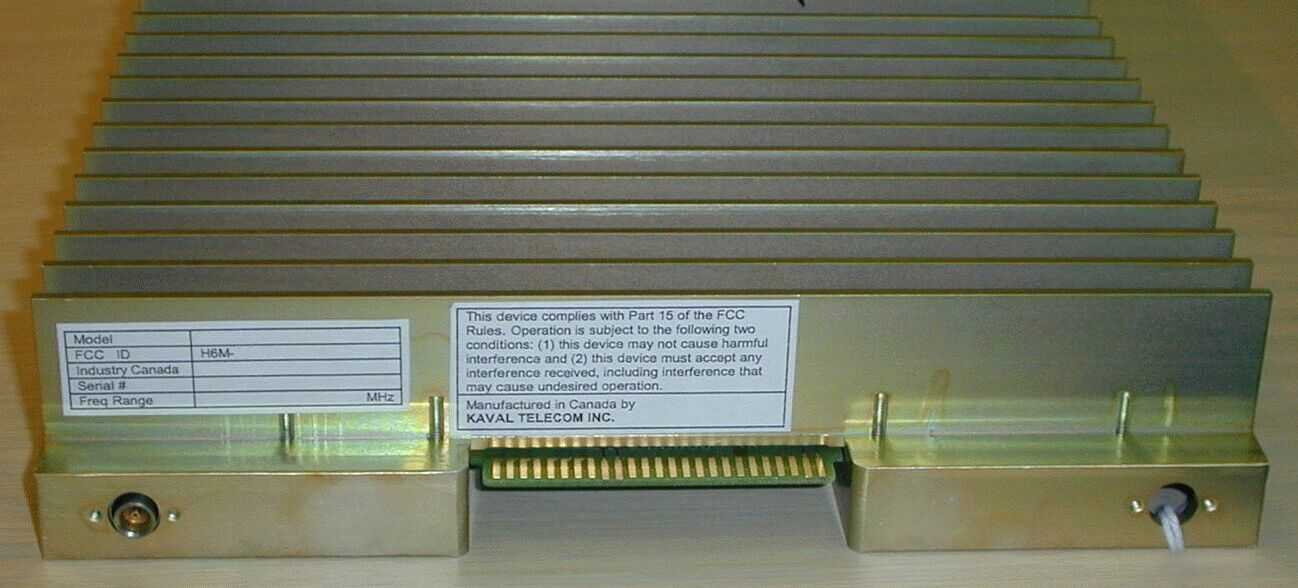
Kaval Wireless Technologies LAB000000021, Rev.0 May 29, 2001 Model LNKC1900- FCC ID H6M-LNKC1900 Industry Canada TBD Serial # Freq Range MHz This device complies with Part 15 of the FCC Rules. Operation is subject to the following two conditions: (1) this device may not cause harmful interference and (2) this device must accept any interference received, including interference that may cause undesired operation. Manufactured in Canada by KAVAL WIRELESS TECHNOLOGIES
Internal Photos
ANNEX 4A - INTERNAL PHOTOGRAPHSPLOT # 1 ANNEX 4A - INTERNAL PHOTOGRAPHSPLOT # 2 ANNEX 4A - INTERNAL PHOTOGRAPHSPLOT # 3 ANNEX 4A - INTERNAL PHOTOGRAPHSPLOT # 4 ANNEX 4A - INTERNAL PHOTOGRAPHSPLOT # 5 ANNEX 4A - INTERNAL PHOTOGRAPHSPLOT # 6 ANNEX 4A - INTERNAL PHOTOGRAPHSPLOT # 7 ANNEX 4A - INTERNAL PHOTOGRAPHSPLOT # 8 ANNEX 4A - INTERNAL PHOTOGRAPHSPLOT # 9 ANNEX 4A - INTERNAL PHOTOGRAPHSPLOT # 10 ANNEX 4A - INTERNAL PHOTOGRAPHSPLOT # 11
Internal Photos
ANNEX 4B - INTERNAL PHOTOGRAPHSPLOT# 12 ANNEX 4B - INTERNAL PHOTOGRAPHSPLOT# 13 ANNEX 4B - INTERNAL PHOTOGRAPHSPLOT# 14
Operational Description
60 Gough Rd., Markham, Ontario, L3R8X7 www.kaval.com, 905-940-3860, 905-946-3003 FAX Operational Description for LNKC1900 LinkNet 1.9 GHz LinkNet PCS Amplifiers June 19, 2001 Theory Of Operation A LINKNET CDMA PCS MODULE is a banded repeater amplifier. The most common LINKNET CDMA PCS MODULE applications are the extension of above ground signals into buildings, tunnels, vehicles or the extension of radio coverage patterns into outdoor shaded areas such as deep valleys. From an applications standpoint, an LINKNET CDMA PCS MODULE is very similar to a regular two-way radio repeater. On Frequency Radio Repeaters can be combined using regular two-way radio multicoupling or duplexing equipment and have input and output signal characteristics to those of regular transmitters and receivers. The one special consideration in LINKNET CDMA PCS MODULE systems is that of input to output antenna isolation. This must be carefully engineered for each installation. The Modules are designed for indoor use only and are intended for mounting in a standard EIA 19 inch rack. Modular design of LINKNET CDMA PCS MODULE circuitry allows for easy servicing, stocking of spares, adaptability and upgrade ability. LNKC1900 MODULE FAMILY MODEL TYPE FREQUENCY LNKC1900-D DownLink 1.25MHz BandWidth 1930 to 1990 MHz LNKC1900-D5 DownLink 5MHz BandWidth 1930 to 1990 MHz LNKC1900-D15 DownLink 15MHz BandWidth 1930 to 1990 MHz LNKC1900-U UpLink 1.25MHz BandWidth 1850 to 1910 MHz LNKC1900-U5 UpLink 5MHz BandWidth 1850 to 1910 MHz LNKC1900-U15 UpLink 15MHz BandWidth 1850 to 1910 MHz Models LNKC1900 RF Module Transmit Board UMC Controller Board with TCXO Receive Board IF Board RF Input 1.8/1.9GHz RF Output 1.8/1.9GHz Micro- Controller with lines to all Boards Blind-Mate to SMA RF Connector Blind-Mate to SMA RF Connector Power & Control to Backplane Communication Interfaces Power Sense Low Noise Pre-AmplifierBuffer Amplifiers Local Oscillator Buffers, Filters, and Linear Power Amplifier Power Circuits Local Oscillator Band Selecting SAW Filter Digital Gain Control Digital Gain Control
Parts List/Tune Up Info
LinkNetô LinkNetôLinkNetô LinkNetô LNKC1900 RF 1900MHz PCS MODULES LNKC1900 RF 1900MHz PCS MODULESLNKC1900 RF 1900MHz PCS MODULES LNKC1900 RF 1900MHz PCS MODULES USER MANUAL USER MANUALUSER MANUAL USER MANUAL INSTALLATION, OPERATION INSTALLATION, OPERATIONINSTALLATION, OPERATION INSTALLATION, OPERATION AND MAINTENANCE AND MAINTENANCEAND MAINTENANCE AND MAINTENANCE KAVAL WIRELESS TECHNOLOGIES 60 Gough Road Markham, Ontario, L3R 8X7 Telephone: (888) 86-KAVAL Web: www.kaval.com E-mail: [email protected] Document #DCM000000053, Rev.2 May 30, 2001 LinkNetô LNKC1900 RF MODULES ! USER MANUAL DCM000000053 Printed: 2001-05-30 10:37:48 Revision Date: 5/30/01: ii P PP P P PP P R RR R R RR R O OO O O OO O P PP P P PP P R RR R R RR R I II I I II I E EE E E EE E T TT T T TT T A AA A A AA A R RR R R RR R Y YY Y Y YY Y S SS S S SS S T TT T T TT T A AA A A AA A T TT T T TT T E EE E E EE E M MM M M MM M E EE E E EE E N NN N N NN N T TT T T TT T © 2000 KAVAL WIRELESS TECHNOLOGIES All rights reserved. No part of this publication, or any software included with it may be reproduced, stored in a retrieval system, or transmitted in any form or by any means, including photocopying, electronic, mechanical, recording or otherwise, without the prior written permission of the copyright holder. This document contains proprietary information of KAVAL WIRELESS TECHNOLOGIES The contents are confidential and any disclosure to persons other than the officers, employees, agents or subcontractors of the owner or licensee of this document, without the prior written consent of KAVAL WIRELESS TECHNOLOGIES, is strictly prohibited. KAVAL WIRELESS TECHNOLOGIES provides this document as is, without any warranty of any kind either expressed or implied including, but not limited to, the implied warranties of merchantability and fitness of a particular purpose. KAVAL WIRELESS TECHNOLOGIES may make changes or improvements in the equipment, software, or specifications described in this document at any time and without notice. These changes will be incorporated in new releases of this document. This document may contain technical inaccuracies or typographical errors. KAVAL WIRELESS TECHNOLOGIES waives responsibility for any labour, materials, or costs incurred by any person or party as a result of using this document. KAVAL WIRELESS TECHNOLOGIES, and any of its affiliates shall not be liable for any damages (including, but not limited to, consequential, indirect or incidental, special damages or loss of profits or date) even if they were foreseeable and KAVAL WIRELESS TECHNOLOGIES has been informed of their potential occurrence, arising out of or in connection with this document or its use. T TT T T TT T R RR R R RR R A AA A A AA A D DD D D DD D E EE E E EE E M MM M M MM M A AA A A AA A R RR R R RR R K KK K K KK K N NN N N NN N O OO O O OO O T TT T T TT T I II I I II I C CC C C CC C E EE E E EE E This manual makes reference to trademarks that are the property of other companies. References are used only to refer to the products or services of the trademark owners. LinkNetô is a trademark of KAVAL WIRELESS TECHNOLOGIES LinkNetô LNKC1900 RF MODULES ! USER MANUAL DCM000000053 Printed: 2001-05-30 10:37:48 Revision Date: 5/30/01: iii TABLE OF TABLE OF TABLE OF TABLE OF CONTENTS CONTENTSCONTENTS CONTENTS 1. LNKC1900 MODULES.............................. 4 OVERVIEW.............................................................. 4 Theory Of Operation ......................................... 4 MODELS................................................................. 4 BLOCK DIAGRAM..................................................... 5 LNKC1900 RF Module...................................... 5 MODULE SPECIFICATIONS....................................... 6 OPERATION............................................................ 7 Software Set-up ................................................ 7 Configuration..................................................... 7 Recommended De-Rating Chart ...................... 8 Power On Self Test (POST).............................. 8 Normal Operation.............................................. 9 LINKNET CDMA PCS MODULE Module ....... 10 ANTENNA INSTALLATION........................................ 11 LinkNetô LNKC1900 RF MODULES ! USER MANUAL DCM000000053 Printed: 01.05.30,10:37 Revision Date:5/30/01 4 Theory Of Operation A LINKNET CDMA PCS MODULE is a banded repeater amplifier. The most common LINKNET CDMA PCS MODULE applications are the extension of above ground signals into buildings, tunnels, vehicles or the extension of radio coverage patterns into outdoor shaded areas such as deep valleys. From an applications standpoint, an LINKNET CDMA PCS MODULE is very similar to a regular two-way radio repeater. On Frequency Radio Repeaters can be combined using regular two-way radio multicoupling or duplexing equipment and have input and output signal characteristics to those of regular transmitters and receivers. The one special consideration in LINKNET CDMA PCS MODULE systems is that of input to output antenna isolation. This must be carefully engineered for each installation. The Modules are designed for indoor use only and are intended for mounting in a standard EIA 19 inch rack. Modular design of LINKNET CDMA PCS MODULE circuitry allows for easy servicing, stocking of spares, adaptability and upgrade ability. LNKC1900 MODULE FAMILY MODEL TYPE FREQUENCY LNKC1900-D DownLink 1.25MHz BandWidth 1930 to 1990 MHz LNKC1900-D5 DownLink 5MHz BandWidth 1930 to 1990 MHz LNKC1900-D15 DownLink 15MHz BandWidth 1930 to 1990 MHz LNKC1900-U UpLink 1.25MHz BandWidth 1850 to 1910 MHz LNKC1900-U5 UpLink 5MHz BandWidth 1850 to 1910 MHz LNKC1900-U15 UpLink 15MHz BandWidth 1850 to 1910 MHz 1. LNKC1900 MODULES Overview Models LinkNetô LNKC1900 RF MODULES ! USER MANUAL DCM000000053 Printed: 01.05.30,10:37 Revision Date:5/30/01 5 LNKC1900 RF Module Block diagram Transmit Board UMC Controller Board with TCXO Receive Board IF Board RF Input 1.8…
Text truncated - open the document above for the full version.
Test Report
May 30, 2001 TIMCO ENGINEERING INC. 849 NW State Road 45 Newberry, Florida 32669 USA Subject:Type Acceptance Application under FCC CFR 47, Parts 2 and 24 (Subpart E) - Personal Communications Services in the Frequency Band 1850 - 1910 MHz (uplink) and 1930-1990 MHz (downlink). Applicant:KAVAL WIRELESS TECHNOLOGIES INC. Product:PCS 1900 MHz Bi-Directional Amplifier Model:LNKC1900 FCC ID:H6M-LNKC1900 Dear Sir/Madam, As appointed agent for KAVAL WIRELESS TECHNOLOGIES INC., we would like to submit the application to the Federal Communications Commission for certification of the above product. Please review all necessary files uploaded to your website site for detailed information. If you have any queries, please do not hesitate to contact us by our TOLL FREE numbers: OUR TELEPHONE NO.:1-877-765-4173 Yours truly, Tri Minh Luu, P. Eng., V.P., Engineering TML/DH Encl. 2 3000 Bristol Circle, Oakville, Ontario, Canada L6H 6G4 Telephone (905) 829-1570 Facsimile (905) 829-8050 Website: www.ultratech-labs.com Email: [email protected] UltraTech Group of Labs 2 3000 Bristol Circle, Oakville, Ontario, Canada L6H 6G4 Telephone (905) 829-1570 Facsimile (905) 829-8050 Website: www.ultratech-labs.com Email: [email protected] May 30, 2001 KAVAL WIRELESS TECHNOLOGIES INC. 60 Gough Road Markham, Ontario Canada, L3R 8X7 Attn.:Mr. Alan Aslett Subject:Certification Testing in accordance with FCC CFR 47, Parts 2 and 24 (Subpart E) - Personal Communications Services in the Frequency Band 1850 - 1910 MHz (uplink) and 1930-1990 MHz (down link). Product:PCS 1900 MHz Bi-Directional Amplifier Model:LNKC1900 Dear Mr. Aslett, The product sample has been tested in accordance with FCC CFR 47, Parts 2 and 24 (Subpart E) - Personal Communications Services in the Frequency Band 1850 - 1910 MHz (uplink) and 1930-1990 MHz (down link), and the results and observation were recorded in the engineering report, Our File No.: KTI-016FCC Enclosed you will find copy of the engineering report. If you have any queries, please do not hesitate to contact us. Yours truly, Tri Minh Luu, P.Eng Vice President - Engineering Encl. UltraTech Group of Labs PCS 1900 MHz Bi-Directional Amplifier Model No.: LNKC1900 FCC ID: H6M-LNKC1900 Applicant:KAVAL WIRELESS TECHNOLOGIES INC. 60 Gough Road Markham, Ontario Canada, L3R 8X7 Tested in Accordance With Federal Communications Commission (FCC) PERSONAL COMMUNICATIONS SERVICES CFR 47, PARTS 2 and 24 (Subpart E) UltraTech's File No.: KTI-016FCC This Test report is Issued under the Authority of Tri M. Luu, Professional Engineer, Vice President of Engineering UltraTech Group of Labs Date: May 30, 2001 Report Prepared by: Tri M. LuuTested by: Mr. Hung Trinh, EMI/RFI Technician Issued Date: May 30, 2001Test Dates: May 18 - May 23, 2001 The results in this Test Report apply only to the sample(s) tested, and the sample tested is randomly selected. UltraTech 3000 Bristol Circle, Oakville, Ontario, Canada, L6H 6G4 Telephone (905) 829-1570 Facsimile (905) 829-8050 Website: www.ultratech-labs.com Email: [email protected] FCC PARTS 2 & 24 PERSONAL COMMUNICATIONS SERVICES, SUBPART E - Broadband PCSContents i PCS 1900 MHz Bi-Directional Amplifier, Model LNKC1900FCC ID: H6M-LNKC1900 ULTRATECH GROUP OF LABSFile #: KTI-016FCC 3000 Bristol Circle, Oakville, Ontario, Canada L6H 6G4May 30, 2001 Tel. #: 905-829-1570, Fax. #: 905-829-8050, Email: [email protected], Website: http://www.ultratech-labs.com • Assessed by ITI (UK) Competent Body, NVLAP (USA) Accreditation Body & ACA/AUSTEL (Australia), VCCI (Japan) • Accredited by Industry Canada (Canada) under ACC-LAB (Europe/Canada MRA and APEC/Canada MRA) • Recognized/Listed by FCC (USA) • All test results contained in this engineering test report are traceable to National Institute of Standards and Technology (NIST) TABLE OF CONTENTS EXHIBIT 1.SUBMITTAL CHECK LIST.......................................................................................................................................1 EXHIBIT 2.INTRODUCTION..........................................................................................................................................................2 2.1.SCOPE..............................................................................................................................................................................................2 2.2.NORMATIVE REFERENCES....................................................................................................................................................2 EXHIBIT 3.PERFORMANCE ASSESSMENT.............................................................................................................................3 3.1.CLIENT INFORMATION...............................................................................................................................................................3 3.2.EQUIPMENT UNDER TEST (EUT) INFORMATION..................................................................................................................3 3.3.EUT’S TECHNICAL SPECIFICATIONS................................................................................................................................4 3.4.LIST OF EUT’S PORTS....................................................................................................................................................................4 3.5.MODIFICATIONS INCORPORATED IN THE EUT FOR COMPLIANCE PURPOSES............................................................................5 3.6.ANCILLARY EQUIPMENT................................................................................................................................................................5 3.7.TEST SETUP..................................................................................................................................................................................5 EXHIBIT 4.EUT OPERATING CONDITIONS AND CONFIGURATIONS D…
Text truncated - open the document above for the full version.
Test Report
ANNEX 2A - PLOTS OF MEASUREMENTSPLOT # 1 ANNEX 2A - PLOTS OF MEASUREMENTSPLOT # 2 ANNEX 2A - PLOTS OF MEASUREMENTSPLOT # 3 ANNEX 2A - PLOTS OF MEASUREMENTSPLOT # 4 ANNEX 2A - PLOTS OF MEASUREMENTSPLOT # 5 ANNEX 2A - PLOTS OF MEASUREMENTSPLOT # 6 ANNEX 2A - PLOTS OF MEASUREMENTSPLOT # 7 ANNEX 2A - PLOTS OF MEASUREMENTSPLOT # 8
Test Report
ANNEX 2A - PLOTS OF MEASUREMENTSPLOT # 9 ANNEX 2A - PLOTS OF MEASUREMENTSPLOT # 10 ANNEX 2A - PLOTS OF MEASUREMENTSPLOT # 11 ANNEX 2A - PLOTS OF MEASUREMENTSPLOT # 12 ANNEX 2A - PLOTS OF MEASUREMENTSPLOT # 13 ANNEX 2A - PLOTS OF MEASUREMENTSPLOT # 14 ANNEX 2A - PLOTS OF MEASUREMENTSPLOT # 15 ANNEX 2A - PLOTS OF MEASUREMENTSPLOT # 16 ANNEX 2A - PLOTS OF MEASUREMENTSPLOT # 17 ANNEX 2A - PLOTS OF MEASUREMENTSPLOT # 18
Test Report
ANNEX 2B - PLOTS OF MEASUREMENTSPLOT # 19 ANNEX 2B - PLOTS OF MEASUREMENTSPLOT # 20 ANNEX 2B - PLOTS OF MEASUREMENTSPLOT # 21 ANNEX 2B - PLOTS OF MEASUREMENTSPLOT # 22 ANNEX 2B - PLOTS OF MEASUREMENTSPLOT # 23 ANNEX 2B - PLOTS OF MEASUREMENTSPLOT # 24 ANNEX 2B - PLOTS OF MEASUREMENTSPLOT # 25 ANNEX 2B - PLOTS OF MEASUREMENTSPLOT # 26 ANNEX 2B - PLOTS OF MEASUREMENTSPLOT # 27 ANNEX 2B - PLOTS OF MEASUREMENTSPLOT # 28
Test Report
ANNEX 2B - PLOTS OF MEASUREMENTSPLOT # 29 ANNEX 2B - PLOTS OF MEASUREMENTSPLOT # 30 ANNEX 2B - PLOTS OF MEASUREMENTSPLOT # 31 ANNEX 2B - PLOTS OF MEASUREMENTSPLOT # 32 ANNEX 2B - PLOTS OF MEASUREMENTSPLOT # 33 ANNEX 2B - PLOTS OF MEASUREMENTSPLOT # 34 ANNEX 2B - PLOTS OF MEASUREMENTSPLOT # 35 ANNEX 2B - PLOTS OF MEASUREMENTSPLOT # 36
Test Report
ANNEX 2C - PLOTS OF MEASUREMENTSPLOT # 37 ANNEX 2C - PLOTS OF MEASUREMENTSPLOT # 38 ANNEX 2C - PLOTS OF MEASUREMENTSPLOT # 39 ANNEX 2C - PLOTS OF MEASUREMENTSPLOT # 40 ANNEX 2C - PLOTS OF MEASUREMENTSPLOT # 41 ANNEX 2C - PLOTS OF MEASUREMENTSPLOT # 42 ANNEX 2C - PLOTS OF MEASUREMENTSPLOT # 43 ANNEX 2C - PLOTS OF MEASUREMENTSPLOT # 44 ANNEX 2C - PLOTS OF MEASUREMENTSPLOT # 45
Test Report
ANNEX 2C - PLOTS OF MEASUREMENTSPLOT # 46 ANNEX 2C - PLOTS OF MEASUREMENTSPLOT # 47 ANNEX 2C - PLOTS OF MEASUREMENTSPLOT # 48 ANNEX 2C - PLOTS OF MEASUREMENTSPLOT # 49 ANNEX 2C - PLOTS OF MEASUREMENTSPLOT # 50 ANNEX 2C - PLOTS OF MEASUREMENTSPLOT # 51 ANNEX 2C - PLOTS OF MEASUREMENTSPLOT # 52 ANNEX 2C - PLOTS OF MEASUREMENTSPLOT # 53 ANNEX 2C - PLOTS OF MEASUREMENTSPLOT # 54 ANNEX 2C - PLOTS OF MEASUREMENTSPLOT # 55
Test Report
ANNEX 2D - PLOTS OF MEASUREMENTSPLOT# 56 ANNEX 2D - PLOTS OF MEASUREMENTSPLOT# 57 ANNEX 2D - PLOTS OF MEASUREMENTSPLOT# 58 ANNEX 2D - PLOTS OF MEASUREMENTSPLOT# 59 ANNEX 2D - PLOTS OF MEASUREMENTSPLOT# 60 ANNEX 2D - PLOTS OF MEASUREMENTSPLOT# 61
Test Report
ANNEX 2D - PLOTS OF MEASUREMENTSPLOT# 59 ANNEX 2D - PLOTS OF MEASUREMENTSPLOT# 60 ANNEX 2D - PLOTS OF MEASUREMENTSPLOT# 61
Test Report
ANNEX 2D - PLOTS OF MEASUREMENTSPLOT# 62 ANNEX 2D - PLOTS OF MEASUREMENTSPLOT# 63 ANNEX 2D - PLOTS OF MEASUREMENTSPLOT# 64 ANNEX 2D - PLOTS OF MEASUREMENTSPLOT# 65
Test Report
ANNEX 2D - PLOTS OF MEASUREMENTSPLOT# 66 ANNEX 2D - PLOTS OF MEASUREMENTSPLOT# 67 ANNEX 2D - PLOTS OF MEASUREMENTSPLOT# 68 ANNEX 2D - PLOTS OF MEASUREMENTSPLOT# 69
Contact Information
Applicant
Robert Biedka(Sr. Quality Engineer)
Technical Contact
Ultratech Engineering Labs Inc.Tri M Luu
[email protected]877-765-4173
3000 Bristol Circle · Oakville · Canada
Test Firm
UltraTech Engineering Labs Inc.Tri Luu
Technical Specifications
| # | Rule Parts | Frequency Range | Power Output | Emission |
|---|---|---|---|---|
| 2 | 24E | 1.93 GHz - 1.99 GHz | 4.3 W | F9W |
Other Applications from Powerwave Technologies Inc.

H6M-LNKA100
Dec 15, 2003LINKNET RF BROADBAND AMPLIFIER MODULE
Equipment Class
AMP - Amplifier
H6M-SB800
Oct 23, 2003In-Hancer Plus Bi-Directional Amplifier
Equipment Class
AMP - Amplifier
H6M-US1900P
Oct 06, 2003PCB - PCS Licensed Transmitter
Equipment Class
PCB - PCS Licensed Transmitter
H6M-LNKFIB-RA
Oct 02, 2003LNKFIB-R
Equipment Class
PCB - PCS Licensed Transmitter
H6M-SB400
Sep 22, 2003SB400 Bi-Directional Amplifier
Equipment Class
AMP - Amplifier