H6M-LNKFIB-RALNKFIB-R
Powerwave Technologies Inc.
Click to zoom
Application Details
- Equipment Class
- PCB - PCS Licensed Transmitter
- Date of Grant
- Oct 02, 2003
- Application Purpose
- Original Equipment
- Date of Application
- Jun 18, 2003
- Equipment Note
- LNKFIB-R
- Frequency Range
- 1850.00000000 - 1910.00000000
- Company
- Powerwave Technologies Inc.
- Country
- United States
Documents & Files
Document Text
Text extracted from the exhibit documents filed with the FCC. Open a document above to read the original.
Users Manual
LinkNet Satellite Unit (LSU) RF - FIBER Interface Modules User Manual Installation, Operation And Maintenance KAVAL WIRELESS TECHNOLOGIES 60 Gough Road Markham, Ontario, L3R 8X7 Telephone: (888) 86-KAVAL Web: www.kaval.com E-mail: [email protected] Document #DCM000000052, Rev.5a June 17, 2003 SatelLink z USER MANUAL DCM000000052 Printed: 2003-06-19 16:02:58 Revision Date: 6/19/03: ii P P R R O O P P R R I I E E T T A A R R Y Y S S T T A A T T E E M M E E N N T T © 2000 KAVAL WIRELESS TECHNOLOGIES All rights reserved. No part of this publication, or any software included with it may be reproduced, stored in a retrieval system, or transmitted in any form or by any means, including photocopying, electronic, mechanical, recording or otherwise, without the prior written permission of the copyright holder. This document contains proprietary information of KAVAL WIRELESS TECHNOLOGIES The contents are confidential and any disclosure to persons other than the officers, employees, agents or subcontractors of the owner or licensee of this document, without the prior written consent of KAVAL WIRELESS TECHNOLOGIES, is strictly prohibited. KAVAL WIRELESS TECHNOLOGIES provides this document as is, without any warranty of any kind either expressed or implied including, but not limited to, the implied warranties of merchantability and fitness of a particular purpose. KAVAL WIRELESS TECHNOLOGIES may make changes or improvements in the equipment, software, or specifications described in this document at any time and without notice. These changes will be incorporated in new releases of this document. This document may contain technical inaccuracies or typographical errors. KAVAL WIRELESS TECHNOLOGIES waives responsibility for any labour, materials, or costs incurred by any person or party as a result of using this document. KAVAL WIRELESS TECHNOLOGIES, and any of its affiliates shall not be liable for any damages (including, but not limited to, consequential, indirect or incidental, special damages or loss of profits or date) even if they were foreseeable and KAVAL WIRELESS TECHNOLOGIES has been informed of their potential occurrence, arising out of or in connection with this document or its use. T T R R A A D D E E M M A A R R K K N N O O T T I I C C E E This manual makes reference to trademarks that are the property of other companies. References are used only to refer to the products or services of the trademark owners. LSU is a trademark of KAVAL WIRELESS TECHNOLOGIES SatelLink z USER MANUAL DCM000000052 Printed: 2003-06-19 16:02:58 Revision Date: 6/19/03: iii TABLE OF CONTENTS 1. LSU MODULES ........................................ 4 OVERVIEW............................................................. 4 Theory Of Operation......................................... 4 MODELS................................................................. 4 BLOCK DIAGRAMS.................................................. 5 LSU Head-End Module..................................... 5 LSU Remote Module ....................................... 6 CONNECTIONS....................................................... 7 LSU Head-End Module..................................... 7 LSU Remote Module ....................................... 8 LSU Head-End to Remote Interconnects ...... 10 MODULE SPECIFICATIONS..................................... 11 REMOTE MODULE PER-CARRIER DE-RATING......... 12 OPERATION.......................................................... 13 Normal Operation ........................................... 13 Configuration .................................................. 13 LASER SAFETY..................................................... 14 ANTENNA INSTALLATION........................................ 15 SatelLink z USER MANUAL Printed: 03.06.19,16:02 Revision Date:6/19/03 4 Theory Of Operation The LSU RF to Fiber Modules provide a multi-band, multi-service link from a main distribution center to multiple local antennae. RF Signals are distributed in runs of three pairs of Single-Mode Fiber-Optic Distribution Lines, organized as... Fiber Pair #1: 1.9 GHz PCS Services Fiber Pair #2: 800 MHz Cellular Services Fiber Pair #3: 800 MHz iDEN, Public Safety, & Paging Services There are two models.... LSU MODEL DESCRIPTION LNKFIB-H01 This is a 1U high, 19" Rack-Mount Module providing low signal level interfacing between Head-End RF Modules and Single-Mode Fiber-Optic Distribution Lines. One is used for each of the three Fiber Pair Groups, and can service up to four Remote Modules. LNKFIB-R01 This is a Wall-Mounted Remote Module that connects to the Single- Mode Fiber-Optic Distribution Lines and provides eight local Distribution Antennae for Signal Extension. NOTE: With these Modules, there is always a grouping of three (3) of LNKFIB-H01's to every four (4) LNKFIB-R01's. 1. LSU MODULES Overview Models SatelLink z USER MANUAL Printed: 03.06.19,16:02 Revision Date:6/19/03 5 LSU Head-End Module Block Diagrams SM F.O. In S M F.O. Out (P IN Di odes ) (Las ers ) Power Supply Moni tor s FO Laser and PIN Diode 120 / 240 VAC 120/240 VAC Fault Relay PreAmp Laser Diode PreAmps RF Out #1 RF Out #2 RF Out #3 RF Out #4 RF Input SatelLink z USER MANUAL Printed: 03.06.19,16:02 Revision Date:6/19/03 6 LSU Remote Module SM F.O. In SM F.O. Out (PIN (Lasers Four Antenna Ports 1.9GHz Cellular Power Supply Monitors & Power Loose Couplers RF Monitor 2 RF Ports to Ports FO Current 120 / 240 Micro- Circuit r 120/240 CAN RS232 To Head- To PC Green Power On Red Fault LED Fault 24 VDC PreAmp IDEN & PreAmp 1.9GHz Cellular IDEN & 869-894 MHz 1.9 GHz 851-869 MHz 1.8 GHz 824-849 MHz 806-824 MHz Notch 851+ Notch 894- 928-941 MHz 899-902 MHz Antennae on Alternate 1.9GHz 800-900MHz SatelLink z USER MANUAL Printed: 03.06.19,16:02 Revision Date:6/19/03 7 LSU Head-End Module The Head-End has one Downlink RF Input providing the signal for four Downlink Optical Outputs, thus each Head-End Module services one and only one of the three Fiber-Pairs (PCS, Cellular, or iDEN…
Text truncated - open the document above for the full version.
Attestation Statements
60 Gough Rd., Markham, Ontario, L3R8X7 www.kaval.com, 905-940-3860, 905-946-3003 FAX December 5, 2002 ULTRATECH ENGINEERING LABS 905-829-1570, Fax: 905-829-8050 3000 Bristol Circle Oakville, Ont. L6H6G4 Tri M.Luu [[email protected]] Tri; As per our discussion regarding an Industry Canada approval to extend our LNKFIB-R iDEN / Trunking band operation from 851-866 MHz to 851-869 MHz, there have been no actual changes in the product design. The Downlink Filters for that band have enough passband to include the extra 3 MHz. Yours sincerely, ______________________________ Alan C. Aslett, P.Eng. Director of Engineering
Attestation Statements
Page 1 of 2 4/11/2003 Tri Luu From: "Steven Dayhoff" <[email protected]> To: <[email protected]> Sent: Friday, April 11, 2003 8:19 AM Attach: TEXT.htm Subject: Re: Fwd: Extension of operation frequency FCC ID: H6M-LNKFIB-R Hi Tri: Sure. That sounds like a good plan. Steve Dayhoff >>> Tri Luu 04/10/03 03:56PM >>> Hi Mr. Dayhoff, Can we submit the original FCC test report with an additional test report for test results at the highest extended frequency (869 MHz)? Tri Luu ----- Original Message ----- From: Steven Dayhoff To: [email protected] Cc: Rich Fabina Sent: Thursday, April 10, 2003 3:20 PM Subject: Re: Fwd: Extension of operation frequency FCC ID: H6M-LNKFIB-R Hi Tri: They need a new FCCID based on FCC Rules section 2.1043 (frequency determining circuitry change). Regards, Steve Dayhoff, FCC ?------------------------------------------------------------------------------- From: Tri Luu To: Rich Fabina Date: 4/8/03 4:51PM Subject: Extension of operation frequency FCC ID: H6M-LNKFIB-R Dear Mr. Fabina, We would like to extend the FCC Certification for an amplifier product (FCC ID: H6M-LNKFIB-R) from 851-866 MHz to 851-869 MHz. There is only small change in the Rx filter. Please advise us if we can submit the application under Class II Permissive Change? Thanks for your support. Best Regards Tri M. Luu, P.Eng. V.P. - Engineering Page 2 of 2 4/11/2003 Ultratech Engineering Labs Inc. 3000 Bristol Circle Oakville, Ontario Canada L6H 6G4 Email: [email protected] Web Site: www.ultratech-labs.com Phone: (905) 829-1570 Fax: (905-829-8050) CC: Alan Aslett >>> Rich Fabina 04/09/03 02:03PM >>> Please handle the attached inquiry. You may have to coordinate with Joe to keep polices consistent. thanks, rich
Attestation Statements
z Page 1 60 Gough Rd., Markham, Ontario, L3R8X7 www.kaval.com, 905-940-3860, 905-946-3003 FAX June 17, 2003 Federal Communications Commission P.O. Box 429 Columbia, MD, 21045, USA Subject: AGENCY AGREEMENT Dear Sir or Madam; I hereby appoint Ultratech Engineering Labs Inc. to act as our agent in the preparation of an application for equipment authorization of the LSU LNKFIB-RA under parts as required of the FCC Rules and Regulations. I certify that Exhibit 2 properly describes the device for which authorization is sought, that the information described in the User’s Manual will be provided with each item manufactured or distributed by Kaval Wireless Technologies, and that the labels described by exhibit 3 will be affixed to each item manufactured by the applicant. I further certify that appropriate arrangements have been made to assure that production units of this equipment bearing the name and FCC IDENTIFIER listed in this application will continue to comply with the Commission’s requirements. I further certify by signature below that no party (per 47 CFR 1.20012(b)) to the application is subject to a denial of Federal benefits, including FCC benefits, pursuant to Section 5301 of Anti-Drug Abuse Act of 1988, 21 U.S.C. 853(a). This appointment also includes the authority to complete FCC Form 731 on our behalf and sign the application as an authorized agent. Yours sincerely, Name: Alan Aslett, P.Eng. Signature: _________________________________ Title: Director of Engineering - Product Development Date: June 17, 2003
Attestation Statements
FEDERAL COMMUNICATIONS COMMISSION WASHINGTON, D.C. 20554 GRANT OF EQUIPMENT AUTHORIZATION Certification Attention: Alan Aslett, Dir of Eng - Prod Development NOT TRANSFERABLE EQUIPMENT AUTHORIZATION is hereby issued to the named GRANTEE, and is VALID ONLY for the equipment identified hereon for use under the Commission's Rules and Regulations listed below. Kaval Wireless Technologies Inc 60 Gough Road Markham, Ontario L3R 8X7 Canada Date of Grant: 10/23/2001 Application Dated: 07/09/2001 FCC IDENTIFIER H6M-LNKFIB-R Name of Grantee Kaval Wireless Technologies Inc Equipment Class: Amplifier Notes: LNKFIB-R Grant Notes FCC Rule Parts Frequency Range (MHZ) Output Watts Frequency Tolerance Emission Designator 24E 1930 - 1990 0.112 EXTENDR 24E 1930 - 1990 0.112 EXTENDR 22 869 - 894 0.302 EXTENDR 22 869 - 894 0.302 EXTENDR 90 928 - 941 0.245 EXTENDR 90 928 - 941 0.245 EXTENDR 90 851 - 866 0.347 EXTENDR 90 851 - 866 0.347 EXTENDR Outdoor antenna(s) used with this transmitter must be fix - mounted on permanent structures. RF exposure compliance is addressed at the time of licensing, as required by the responsible FCC Bureau (s), including antenna co-location requirements of Section 1.1307(b)(3). Indoor antennas used with this transmitter must be those supplied by the manufacturer and described in the application and must be installed to provide a separation distance of al least .2 M from all persons and must not be co-located in conjunction with any other antenna or transmitter. Installers and end users must be provided with antenna installation instructions and transmitter operating conditions for satisfying RF exposure compliance. Indoor installations must be used with KAVAL 12, 16 or 20 dB Cable Taps. Power output listed is at the maximum value at the antenna connector. Power output per carrier reduces proportionally with additional channel loading. Approved for F9W, DXW, GXW, F3E and F1D Mail To: Tri Luu, Ultratech Engineering Labs Inc. Page 1 of 2 6/16/2003https://gullfoss2.fcc.gov/cgi-bin/ws.exe//prod/oet/forms/misc/Grant_Form.hts?mode=COP... 3000 Bristol Circle Oakville, L6H 6G4 CA EA101646 Page 2 of 2 6/16/2003https://gullfoss2.fcc.gov/cgi-bin/ws.exe//prod/oet/forms/misc/Grant_Form.hts?mode=COP...
Attestation Statements
60 Gough Rd., Markham, Ontario, L3R8X7 www.kaval.com, 905-940-3860, 905-946-3003 FAX October 1, 2003 Federal Communications Commission P.O. Box 429 Columbia, MD, 21045, USA Subject: Sec. 22.383 In-Building Radiation Systems and Sec. 90.219 Use of Signal Boosters. Dear Sir or Madam; This letter is intended to confirm that as regards our submission for our H6M-LNKFIB-RA, we understand and intend to comply with... Sec. 22.383 In-building Radiation Systems. and Sec. 90.219 Use of Signal Boosters. Yours sincerely, Name: Alan Aslett, P.Eng. Signature: _________________________________ Title: Director of Engineering - Product Development Date: October 1, 2003
Block Diagram
SatelLink z USER MANUAL Printed: 03.06.19,16:02 Revision Date:6/19/03 5 LSU Head-End Module Block Diagrams SM F.O. In S M F.O. Out (P IN Di odes ) (Las ers ) Power Supply Moni tor s FO Laser and PIN Diode 120 / 240 VAC 120/240 VAC Fault Relay PreAmp Laser Diode PreAmps RF Out #1 RF Out #2 RF Out #3 RF Out #4 RF Input SatelLink z USER MANUAL Printed: 03.06.19,16:02 Revision Date:6/19/03 6 LSU Remote Module SM F.O. In SM F.O. Out (PIN (Lasers Four Antenna Ports 1.9GHz Cellular Power Supply Monitors & Power Loose Couplers RF Monitor 2 RF Ports to Ports FO Current 120 / 240 Micro- Circuit r 120/240 CAN RS232 To Head- To PC Green Power On Red Fault LED Fault 24 VDC PreAmp IDEN & PreAmp 1.9GHz Cellular IDEN & 869-894 MHz 1.9 GHz 851-869 MHz 1.8 GHz 824-849 MHz 806-824 MHz Notch 851+ Notch 894- 928-941 MHz 899-902 MHz Antennae on Alternate 1.9GHz 800-900MHz SatelLink z USER MANUAL Printed: 03.06.19,16:02 Revision Date:6/19/03 7 LSU Head-End Module The Head-End has one Downlink RF Input providing the signal for four Downlink Optical Outputs, thus each Head-End Module services one and only one of the three Fiber-Pairs (PCS, Cellular, or iDEN/Trunking). Connections Head-End Connections SC/APC SingleMode Fiber-Optic & SMA RF Connectors AC Power Cord Downlink Optical Outputs TX1TX2TX3TX4RX1RX2RX3RX4 Uplink Optical Inputs TX InRX1RX2RX3RX4 Downlink RF Input Uplink RF Outputs SatelLink z USER MANUAL Printed: 03.06.19,16:02 Revision Date:6/19/03 8 LSU Remote Module Antenna Port Connections Four Direct Antenna Connections Two Expansion Antenna Connections Uplink Sampler Port Downlink Sampler Port SMA Connections The Remote Module has 8 SMA RF Connections.. Main Antenna Ports (4): Used to connect to four identical distributed indoor antenna systems. Expansion Antenna Ports (2): Connected to a secondary location via 2 of two-way combiners, and in turn provide connections to four more identical distributed indoor antenna systems. Sampler Ports (2): Optionally allow an operator to monitor the Uplink and Downlink RF activity at approx. 30dB below the actual levels. SatelLink z USER MANUAL Printed: 03.06.19,16:02 Revision Date:6/19/03 9 Fiber Optic Port Connections PCS Uplink Optical Output PCS Downlink Optical Input Cellular Uplink Optical Output iDEN/Paging Uplink Optical Output Cellular Downlink Optical Input iDEN/Paging Downlink Optical Input SC/APC SingleMode Fiber-Optic Connectors The Remote Module has 6 SC/APC Single-Mode Fiber-Optic Connections for cabling to the Head-End... PCS Up & Downlink: Used for the PCS Fiber-Optic Pair connection to the Head-End. Cellular Up & Downlink: Used for the Cellular Fiber-Optic Pair connection to the Head-End. iDEN/Paging Up & Downlink: Used for the combined iDEN / Paging Fiber-Optic Pair connection to the Head-End. SatelLink z USER MANUAL Printed: 03.06.19,16:02 Revision Date:6/19/03 10 LSU Head-End to Remote Interconnects The Single-Mode Fiber-Optic interconnections between the Head-End and Remote Modules are based upon the Head-Ends being organized on a "per Fiber-Pair" system. This fundamentally means that an installation requires three Head-Ends for every four Remote Modules. It also means that if you have a fully optimized system with all Head-End ports in use, and you add one more Remote Module, then another three Head-End Modules are required. Head-End to Remote Fiber-Optic Connections Groupings of 3 Head-Ends to every 4 Remotes PCS Head-End Cell Head-End Head-End iDEN / Paging Remote Module Remote Modules To 3 More Remote Modules To 3 More Remote Modules To 3 More
Cover Letter(s)
June 17, 2003 FEDERAL COMMUNICATIONS COMMISSION 7435 Oakland Mills Road Columbia, MD 21046 USA Subject: Type Acceptance Application under FCC CFR 47, Parts 2, 22, 24 and 90 - Non-Broadcast Bi-directional Radio Amplifiers Operating in the frequency bands 1930-1990 MHz (PCS), 869-894 MHz (Base Cellular), 928-941 MHz (Paging) and 851-869 MHz (Trunking). Applicant: KAVAL WIRELESS TECHNOLOGIES INC. Product: SATELINK RF - FIBER INTERFACE MODULE Model: LNKFIB-R FCC ID: H6M-LNKFIB-RA Dear Sir/Madam, As appointed agent for KAVAL WIRELESS TECHNOLOGIES INC., we would like to submit the application to the Federal Communications Commission for certification of the above product. Please review all necessary files uploaded to FCC OET site for detailed information. Note : This application for the extension of the frequency band from 851-869 MHz to 851-869 MHz of the FCC Grant FCC ID: H6M-LNKFIB-R certified by FCC on Oct. 23, 2003. There is no mechanical/electrical design change for this product. Since there is no mechanical/electrical change applied to this device for extension of operating band from 851-869 MHz to 851-869 MHz. The test plan was discussed with Mr. Mr. Steven Dayhoff at FCC and agreed to perform the following tests at 869 MHz: (1) RF Output Power (2) 99% Occupied BW (3) Emission Mask (4) Transmitter Spurious Conducted Emissions (5) Transmitter Spurious Radiated Emissions Other tests are referred to the original test reports that are re-submitted to FCC for review. If you have any queries, please do not hesitate to contact us by our TOLL FREE numbers: OUR TELEPHONE NO.: 1-877-765-4173 Yours truly, Tri Minh Luu, P. Eng., V.P., Engineering UltraTech Group of La bs 31040/SIT C-1376 46390-2049 200093-0 2 00-034 SL2-IN-E-1119R 3000 Bristol Circle, Oakville, Ontario, Canada L6H 6G4 Tel.: (905) 829-1570 Fax.: (905) 829-8050 Website: www.ultratech-labs.com Email: [email protected]
Cover Letter(s)
z Page 1 60 Gough Rd., Markham, Ontario, L3R8X7 www.kaval.com, 905-940-3860, 905-946-3003 FAX June 17, 2003 Federal Communications Commission Equipment Authorization Branch 7435 Oakland Mills Rd. Columbia, MD, 21046, USA Subject: CONFIDENTIALTY REQUEST Dear Sir or Madam; Kaval Wireless Technologies respectfully requests confidentiality of certain materials provided with the submission of the LSU LNKFIB-RA under FCC ID H6M-LNKFIB-RA in accordance with FCC Regulations 0.459. The confidentiality request applies to the schematic diagrams, SCH000000039, SCH000000046, SCH000000047 and SCH000000048, contained in Exhibit 2. The USU has been developed at considerable effort and expense by Kaval Wireless Technologies. These items are considered as Trade Secrets and therefore public access to the proprietary material could possibly result in duplication of equipment that could severely damage the company’s business advantage. I appreciate your assistance in this manner. Yours sincerely, Name: Alan C. Aslett, P.Eng. Signature: _________________________________ Title: Director of Engineering - Product Development Date: June 17 , 2003
Cover Letter(s)
60 Gough Rd., Markham, Ontario, L3R8X7 www.kaval.com, 905-940-3860, 905-946-3003 FAX December 5, 2002 ULTRATECH ENGINEERING LABS 905-829-1570, Fax: 905-829-8050 3000 Bristol Circle Oakville, Ont. L6H6G4 Tri M.Luu [[email protected]] Tri; As per our discussion regarding an Industry Canada approval to extend our LNKFIB-R iDEN / Trunking band operation from 851-866 MHz to 851-869 MHz, there have been no actual changes in the product design. The Downlink Filters for that band have enough passband to include the extra 3 MHz. Yours sincerely, ______________________________ Alan C. Aslett, P.Eng. Director of Engineering
External Photos
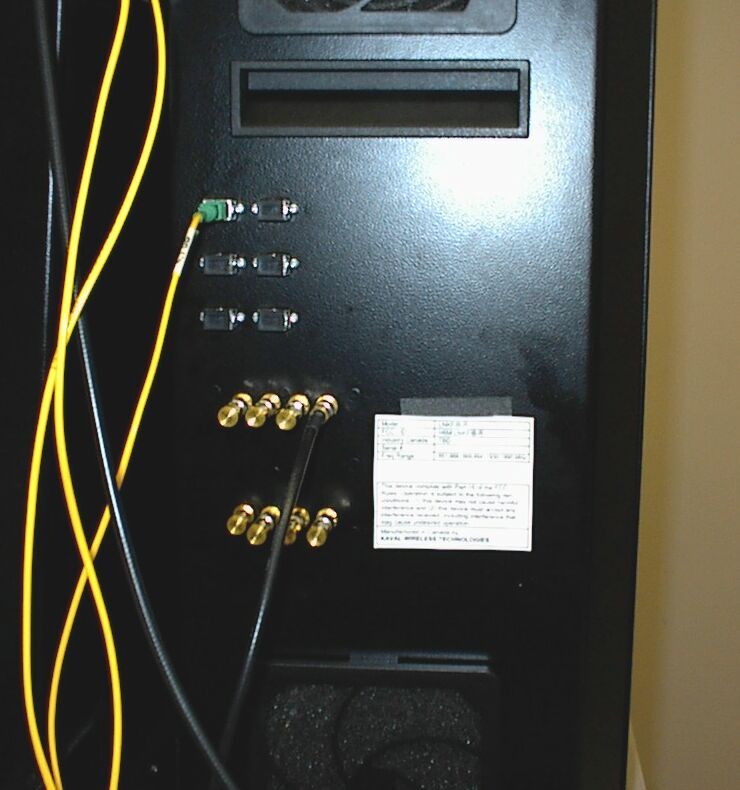
ANNEX 3 - EXTERNAL PHOTOGRAPHS OF KAVAL MODEL LNKFIB-R (SATELINK HEAD-END MODULE & AMPLIFIER MODULE) Photo # 1 Head-End Module Amplifier ANNEX 3 - EXTERNAL PHOTOGRAPHS OF KAVAL MODEL LNKFIB-R (SATELINK HEAD-END MODULE & AMPLIFIER MODULE) Photo # 2 ANNEX 3 - EXTERNAL PHOTOGRAPHS OF KAVAL MODEL LNKFIB-R (SATELINK HEAD-END MODULE & AMPLIFIER MODULE) Photo # 3 ANNEX 3 - EXTERNAL PHOTOGRAPHS OF KAVAL MODEL LNKFIB-R (SATELINK HEAD-END MODULE & AMPLIFIER MODULE) Photo # 4 ANNEX 3 - EXTERNAL PHOTOGRAPHS OF KAVAL MODEL LNKFIB-R (SATELINK HEAD-END MODULE & AMPLIFIER MODULE) Photo # 5 ANNEX 3 - EXTERNAL PHOTOGRAPHS OF KAVAL MODEL LNKFIB-R (SATELINK HEAD-END MODULE & AMPLIFIER MODULE) Photo # 6
ID Label/Location Info
ANNEX 6B - FCC ID LABEL LOCATION FCC ID Label on the Head-End Module ANNEX 6B - FCC ID LABEL LOCATION FCC ID Label on the Amplifier Unit
ID Label/Location Info
Kaval Wireless Technologies LAB000000023, Rev.4 June 17, 2003 Model LNKFIB-R FCC ID H6M-LNKFIB-RA Industry Canada IC: 1541311245A Serial # Freq Range 851-869, 869-894, 928-941, 1930-1990 MHz This device complies with Part 15 of the FCC Rules. Operation is subject to the following two conditions: (1) this device may not cause harmful interference and (2) this device must accept any interference received, including interference that may cause undesired operation. Manufactured in Canada by KAVAL WIRELESS TECHNOLOGIES
Internal Photos
ANNEX 4 - INTERNAL PHOTOGRAPHS OF KAVAL LNKFIB-R AMPLIFIERPhoto # 1 ANNEX 4 - INTERNAL PHOTOGRAPHS OF KAVAL LNKFIB-R AMPLIFIERPhoto # 2 ANNEX 4 - INTERNAL PHOTOGRAPHS OF KAVAL LNKFIB-R AMPLIFIERPhoto # 3 ANNEX 4 - INTERNAL PHOTOGRAPHS OF KAVAL LNKFIB-R AMPLIFIERPhoto # 4 ANNEX 4 - INTERNAL PHOTOGRAPHS OF KAVAL LNKFIB-R AMPLIFIERPhoto # 5 ANNEX 4 - INTERNAL PHOTOGRAPHS OF KAVAL LNKFIB-R AMPLIFIERPhoto # 6 ANNEX 4 - INTERNAL PHOTOGRAPHS OF KAVAL LNKFIB-R AMPLIFIERPhoto # 7 ANNEX 4 - INTERNAL PHOTOGRAPHS OF KAVAL LNKFIB-R AMPLIFIERPhoto # 8 ANNEX 4 - INTERNAL PHOTOGRAPHS OF KAVAL LNKFIB-R AMPLIFIERPhoto # 9 ANNEX 4 - INTERNAL PHOTOGRAPHS OF KAVAL LNKFIB-R AMPLIFIERPhoto # 10 ANNEX 4 - INTERNAL PHOTOGRAPHS OF KAVAL LNKFIB-R AMPLIFIERPhoto # 11 ANNEX 4 - INTERNAL PHOTOGRAPHS OF KAVAL LNKFIB-R AMPLIFIERPhoto # 12 ANNEX 4 - INTERNAL PHOTOGRAPHS OF KAVAL LNKFIB-R AMPLIFIERPhoto # 13 ANNEX 4 - INTERNAL PHOTOGRAPHS OF KAVAL LNKFIB-R AMPLIFIERPhoto # 14 ANNEX 4 - INTERNAL PHOTOGRAPHS OF KAVAL LNKFIB-R AMPLIFIERPhoto # 15 ANNEX 4 - INTERNAL PHOTOGRAPHS OF KAVAL LNKFIB-R AMPLIFIERPhoto # 16
Internal Photos
ANNEX 4 - INTERNAL PHOTOGRAPHS OF KAVAL LNKFIB-R HEAD-END MODULEPhoto # 17 ANNEX 4 - INTERNAL PHOTOGRAPHS OF KAVAL LNKFIB-R HEAD-END MODULEPhoto # 18 ANNEX 4 - INTERNAL PHOTOGRAPHS OF KAVAL LNKFIB-R HEAD-END MODULEPhoto # 19 ANNEX 4 - INTERNAL PHOTOGRAPHS OF KAVAL LNKFIB-R HEAD-END MODULEPhoto # 20
Operational Description
60 Gough Rd., Markham, Ontario, L3R8X7 www.kaval.com, 905-940-3860, 905-946-3003 FAX Operational Description for LNKFIB-R01 & H01 SatelLink Fiber System June 19, 2001 Theory Of Operation The SatelLink RF to Fiber Modules provide a multi-band, multi-service link from a main distribution center to multiple local antennae. RF Signals are distributed in runs of three pairs of Single-Mode Fiber-Optic Distribution Lines, organized as... Fiber Pair #1: 1.9 GHz PCS Services Fiber Pair #2: 800 MHz Cellular Services Fiber Pair #3: 800 MHz iDEN & Paging Services There are two models.... SatelLink MODEL DESCRIPTION LNKFIB-H01 This is a 1U high, 19" Rack-Mount Module providing low signal level interfacing between Head-End RF Modules and Single-Mode Fiber-Optic Distribution Lines. One is used for each of the three Fiber Pair Groups, and can service up to four Remote Modules. LNKFIB-R01 This is a Wall-Mounted Remote Module that connects to the Single- Mode Fiber-Optic Distribution Lines and provides eight local Distribution Antennae for Signal Extension. NOTE: With these Modules, there is always a grouping of three (3) of LNKFIB-H01's to every four (4) LNKFIB- R01's. Models SatelLink Head-End Module SM F.O. In S M F.O. Out (PIN Diodes) (Las ers ) Power Supply Mo ni t or s FO Laser and PIN Diode 120 / 240 VAC 120/240 VAC Fault Relay PreAmp Laser Diode PreAmps RF Out #1 RF Out #2 RF Out #3 RF Out #4 RF Input SatelLink Remote Module SM F.O. In SM F.O. Out (PIN Diodes) (Lasers) Four Antenna Ports 1. 9G Hz PCS Cellular Power Supply Monitor s & Power Amp Loose Coupler s RF Monitor 2 RF Ports to Ports FO Cur rent 120 / 240 VAC Micro-Controller Circuitry 120/240 VAC CAN Interface RS232 Interface To Head-End To PC Green P ower On LE D Red Fault LE D Fault Relay 24 VDC Battery PreAmps IDEN & Paging PreAmps 1. 9G Hz PCS Cellular IDEN & Paging 869-894 M Hz 1. 9 G Hz 851-866 M Hz 1. 8 G Hz 824-849 M Hz 806-821 M Hz Not c h 851+ M Hz Not c h 894- M Hz 928-941 MHz 899-902 M Hz Antennae on Alter nate Floor 1. 9G Hz PA 800-900MHz PA SatelLink Head-End to Remote Interconnects Head-End to Remote Fiber-Optic Connections Groupings of 3 Head-Ends to every 4 Remotes PCS Head-End Cell Head-End Head-End iDEN / Paging Remote Module Remote Modules To 3 More Remote Modules To 3 More Remote Modules To 3 More The Single-Mode Fiber-Optic interconnections between the Head-End and Remote Modules are based upon the Head-Ends being organized on a "per Fiber-Pair" system. This fundamentally means that an installation requires three Head-Ends for every four Remote Modules. It also means that if you have a fully optimized system with all Head-End ports in use, and you add one more Remote Module, then another three Head-End Modules are required.
Operational Description
DESIGN GUIDE FIBER OPTIC TRANSMITTERS, RECEIVERS, TRANSCEIVERS AND SUBSYSTEMS FOR WIRELESS AND RF SIGNAL DISTRIBUTION • PCS/PCN • DISTRIBUTED ANTENNA • CELLULAR • 70/140 MHz IF • ANTENNA REMOTING • WIRELESS LOCAL LOOP • LMDS • RADAR SYSTEMS • ESMR RF ON FIBER ™ FOR WIRELESS APPLICATIONS HIGHWAY OR LONG DISTANCE BACKHAUL SYSTEMS The beauty of fiber optic transmission is its low RF loss over long distances. Anacom offers fiber optic subsystems that can transmit over 20km, 30km or more. A trunk line system can be designed using bidirectional optical taps at the antenna sites. And with the use of WDM technology, fiber usage can be reduced by half or more. WDM TRANSCEIVER Wavelength Division Multiplexing is an optical tech- nique that allows two or more optical signals to be combined onto a single fiber. WDM is widely used to reduce fiber leasing costs. In a typical sys- tem, both the uplink and down- link paths are multiplexed onto a single fiber. In advanced sys- tem designs, a third channel for uplink antenna diversity is provided–all on one fiber. WIRELESS LOCAL LOOP TRANSCEIVER New wireless local loop systems are being designed with fiber antenna distribution as a funda- mental system design approach. Systems designers are taking advantage of fibers ability to remote the RF heads and to con- solidate the modulators at a common location. The AC 206-2.5 has a flat pass band up to 2.5 GHz. Optical splitters and combiners can be incorporated for unique optical system configurations. IN-BUILDING DISTRIBUTED ANTENNA Assure reliable and ubiquitous coverage with a fiber based dis- tributed antenna system. Cost- effective fiber optic transceiver modules can be distributed throughout a building, mall, sub- way station or any location where consistent coverage is required. The head end unit can be located anywhere on the premises, as the performance of the system is maintained even over long fiber runs. WELCOME TO THE WIRELESS REVOLUTION Whether you operate in the city, in the suburbs, over long highway runs or in- building, Anacom Systems Corporation offers you a fiber optic solution that will make your wireless network work reliably and ubiquitously. Anacom’s high perform- ance, yet cost-effective rugged fiber optic transceivers give you the freedom to go far and wide, with impunity. Welcome to the wireless revolution. RFON FIBER ™ CELLULAR BAND TRANSCEIVER The AC 106 is optimized for use in the cellular band of 800 to 1000 MHz. This transceiver, as is the case with all our fiber optic transceivers, is trans- parent to the signal format or modulation technique. Higher power and high spur-free dynamic range options are available. PCS TRANSCEIVER The AC 206 is a high performance broadband transceiver optimized for PCS antenna remoting appli- cations. It provides flat bandwidth from 1700 to 2200 Mhz and a wide spur-free dynamic range greater than 100dB/Hz 2/3 . The unit utilizes advance MQW laser diode technology for stable wide tem- peraturerange performance. LNA AMP Fiber Optic Transceiver Fiber Optic Transceiver Duplexer Antenna Fiber RF in RF out RF/Fiber Optic are used between the remote antenna and the base station. The remote unit usually includes an LNA for the uplink and a linear power amplifier for the downlink. If a commonantenna is used for both transmit and receive, a duplexer ties the two paths together. TX & RX modules, DC powered FC/APC and SC/APC fiber optic connectors 19” Subrack Unit, AC powered WITH ITS BROAD BANDWIDTH AND CAPACITY FOR UNLIMITED EXPANSIONFIBER OPTICS IS IDEAL FOR TODAY ’S AND TOMORROW’S APPLICATIONS. Fiber Optic transmission is the most efficient means to transmit Wireless and RF signals. Fiber cable has a much lower signal loss, is much lighter and is much less expensive than coaxial cable. For these reasons alone, fiber optics has grown to be a significant factor in the wireless revolution. Transmitter The fiber optic transmitter converts an RF signal into an optical signal at 1.3 um.The input impedance of the transmitter is 50 ohms. The output is an optical signal whose amplitude (or brightness) is proportional to the RF voltage input. This is referred to as direct or intensity modulation. The laser diode driver circuitry utilizes optical feedback to maintain the optical output of the laser constant. An optical detector internal to the laser transmitter is used to monitor the output power and to adjust the bias current of the laser to maintain a constant average optical output. This …
Text truncated - open the document above for the full version.
Contact Information
Applicant
Robert Biedka(Sr. Quality Engineer)
Technical Contact
Ultratech Engineering Labs Inc.Tri M Luu
[email protected]1-877-747-6381
3000 Bristol Circle · Oakville, Ontario · Canada
Non-Technical Contact
Ultratech Engineering Labs Inc.Tri M Luu
[email protected]1-877-747-6381
Test Firm
UltraTech Engineering Labs Inc.Tri Luu
Technical Specifications
| # | Rule Parts | Frequency Range | Power Output | Emission |
|---|---|---|---|---|
| 2 | 24E | 1.85 GHz - 1.91 GHz | 21.00 µW | GXW |
Other Applications from Powerwave Technologies Inc.

H6M-LNKA100
Dec 15, 2003LINKNET RF BROADBAND AMPLIFIER MODULE
Equipment Class
AMP - Amplifier
H6M-SB800
Oct 23, 2003In-Hancer Plus Bi-Directional Amplifier
Equipment Class
AMP - Amplifier
H6M-US1900P
Oct 06, 2003PCB - PCS Licensed Transmitter
Equipment Class
PCB - PCS Licensed Transmitter
H6M-SB400
Sep 22, 2003SB400 Bi-Directional Amplifier
Equipment Class
AMP - Amplifier
H6M-US800TP
Aug 12, 2003LinkNet UniServ Unit, Model US800TP
Equipment Class
TNB - Licensed Non-Broadcast Station Transmitter