H78KPMT2WVHF Automatic Meter Reading Transceiver with 2.4 GHz TX
KP Electronic Systems Ltd
Click to zoom
Application Details
- Equipment Class
- TNB - Licensed Non-Broadcast Station Transmitter
- Date of Grant
- Oct 25, 2015
- Application Purpose
- Original Equipment
- Date of Application
- Oct 25, 2015
- Equipment Note
- VHF Automatic Meter Reading Transceiver with 2.4 GHz TX
- Frequency Range
- 172.50000000 - 173.50000000
- Company
- KP Electronic Systems Ltd
- Country
- Israel
Documents & Files
Document Text
Text extracted from the exhibit documents filed with the FCC. Open a document above to read the original.
Users Manual
MT2W™ Long-Range Synthesized Radio Meter Transmitter Installation Manual Web Site: www.kpsystems.com ISRAEL Office Email: [email protected] Tefen Industrial Park, Tefen 24959 Tel: 972-4-987-3066 Fax: 972-4-987-3692 USA Office: KP ELECTRONICS INC. Email: [email protected] 415 Sargon way , Suite F Horsham PA 19044 Book 144 Approved: Efi Rev: NEW 21-Oct-15 MT2W™ General Description The MT2W™ is a 2W output power and -117DBm sensitivity long-range, synthesized radio-metering transceiver for narrow band wireless networks in the VHF 136-174 MHZ frequency band. At a preprogrammed interval (default is every hour) the MT2W interrogates the register to obtain the most recent read, and transmits the data to the central receiver. Unit parameters and meters values are easily programmed using the GUP5000™ utility-programming software (see the MT2W ™ Programming Guide) or by the FTU. The MT2W™ has one connector (see Figure 1). 1. Meter Input: The meter input is either a single three-wire or double three-wire cable, depending on factory configuration. These wires connect to the meter output. Figure 1: MT2W™ View Preparing for Operation Before installing the MT2W on site, perform the following preparations: 1. Setting communication parameters 2. Self test Setting Communication Parameters Connect GUP5000 program to the MT2W (see the MT2W™ Programming Manual) Self-Test See the Field Programmer User Guide for directions on performing a self-test. Signal Level Verification Before attaching the MT2W to the mounting bracket, verify signal level in the planned mounting location, by following these steps: 1. Turn on the FTU101 signal strength unit. 2. Hold the MT2W in the planned mounting location (after connecting the 3 wires to the register – see the Wiring section for directions how to connect the MT2W to the register) and swipe the magnet along the bottom of the unit. 3. Look at the FTU101 screen, and make sure you get a good or full signal from at least one of the repeaters that is receiving the ID of the MT2W that was just activated. 4. If the strongest signal received is only a weak signal, move the MTU to another location, wait 20 seconds and swipe the magnet along the bottom of the unit again. 5. Repeat step 4 until the location with the best signal level is found. Installing the MT2W™ There are two mounting methods: Wall mounting On-pipe mounting Wall Mounting Installation Figure 2: Wall Mounting 1. Fasten the mounting bracket on the wall with four screws (See figure 2) 2. Slide the MT2W unit on the mounting bracket until the 4 clips lock the unit 3. Define the parameters with the field programmer (FTU100) see the FTU User Guide 4. Swipe the magnet along the bottom of the MT2W unit. The MT2W wakes and sends a transmission. On-pipe Mounting Installation Figure 3: On-pipe Mounting 1. Fasten the mounting bracket on the pipe with two screws and the “Omega” bracket (See figure 3) 2. Slide the MT2W unit on the mounting bracket until the 4 clips lock the unit 3. Define the parameters with the field programmer (FTU100) see the FTU User Guide 4. Swipe the magnet along the bottom of the MT2W unit. The MT2W wakes and sends a transmission. Restrictions Before installation pay attention to the following restrictions: 1. Do not mount the MT2W on any metallic surface. 2. Do not run wires next to the MT2W antenna. 3. Do not mount the MT2W horizontally. Always mount unit with antenna facing upwards. 4. Do not wrap excess wire around the MT2W. 5. When installing more than a one MT2W in the same site, make sure you keep distance of at least 3 ft. between two adjacent the MT2W units installed on the same wall/surface. Wiring 1. Connect the three wires from the MT2W to the register wires using a self-stripping insulated connector (3M- Scotchlock™ or equivalent), or directly to the register terminals. Connect as follows: MT2W Wire Register Wire/Terminal Green Green Red Red Black Black 2. Polarity: If a Passive Pulse type meter is connected, there is no polarity and the wires can be connected in any order If an Active Pulse type meter is connected, there is a polarity and the wires have to be connected in the following order: Red wire to the POSITIVE (+) poll Black wire to the NEGATIVE () poll. Figure 4: Wiring Technical Specifications Operating Voltage 8–15 VDC Standby Current 30μA max. Tx Current 0.8A max. Power Output 2W Freq. Stability 5ppm at operating temp. range Operating Temp. -22F 120F (-30C 60C) Storage Temp. -40F 158F (-40C 70C) Weight 0.5 lb. (230 gr.) NOTICE The information in this document has been carefully checked and is considered reliable. No responsibility is assumed for inaccuracies. KP ELECTRONIC SYSTEMS LTD. reserves the right to introduce changes in its products to improve reliability, function, or design. KP ELECTRONIC SYSTEMS LTD. does not assume any liability arising from the application or use of any of its products or any product described in this document, nor does it convey any license under its patent rights or the rights of others. This document contains proprietary information and may not be reproduced in any form without prior written consent of KP ELECTRONIC SYSTEMS LTD. *Other names and brands may be claimed as the property of others. Copyright 2015 by KP ELECTRONIC SYSTEMS LTD., PO Box 42, Tefen Industrial Park, Tefen 24959, Israel. All rights reserved. FCC INFORMATION TO USER THIS DEVICE COMPLIES WITH PART 15 OF THE FCC RULES. OPERATION IS SUBJECT TO THE FOLLOWING TWO CONDITIONS: (1) THIS DEVICE MAY NOT CAUSE HARMFUL INTERFERENCE, AND (2) THIS DEVICE MUST ACCEPT ANY INTERFERENCE RECEIVED, INCLUDING INTERFERENCE THAT MAY CAUSE UNDESIRED OPERATION. NOTE: KP IS NOT RESPONSIBLE FOR ANY CHANGES OR MODIFICATIONS NOT EXPRESSLY APPROVED BY THE PARTY RESPONSIBLE FOR COMPLIANCE. SUCH MODIFICATIONS COULD VOID THE USER’S AUTHORITY TO OPERATE THE EQUIPMENT.
Attestation Statements
P.O.Box 42 Tefen Industrial Park 2495900 Tefen Tel: 972-4-9873066, Fax: 972-4-9873692 [email protected]: -E www.kpsystems.com Federal Communications Commission Authorization and Evaluation Division, 7435 Oakland Mills Road Columbia, MD 21046 USA Re: FCC ID: H78KPMT2W Attestation Statement per 90.203(e) and (g) Programming of transceiver frequencies can only be performed by the manufacturer or authorized service and maintenance personnel. The radio output power is fixed and can’t be changed. In addition, there is no RF connector – just integrated internal antenna. Sincerely, Liad Kenig VP, KP Electronic Systems, Ltd.
Cover Letter(s)
P.O.Box 42 Tefen Industrial Park 2495900 Tefen Tel: 972-4-9873066, Fax: 972-4-9873692 [email protected]: -E www.kpsystems.com Federal Communication Commission Authorization and Evaluation Division Confidentiality Request regarding application for certification of FCC ID: H78KPMT2W Pursuant to Section 0.457 and 0.459 of the Commission’s Rules, we hereby request confidential treatment of information accompanying this application as below: 1. BLOCK DIAGRAM & SCHEMATICS 2. MT2W1 Specification & Circuit Description & Radio Tuning Procedures The applicant understands that pursuant to Section 0.457 of the Rules, disclosure of this application and all accompanying documentation will not be made before the date of the Grant for this application. Sincerely, Liad Kenig VP
Parts List/Tune Up Info
ELB188 05 Rev: MT2W Board Part List of: Description: Cat.No.DescriptionLocation Qty Rev: Page 1 of 5 Manuf. P/N 1ANT1000 Antenna Chip 2.45 GHz SMD 1206 ANT12450AT18A100 2450AT18A100E ANT3216LL00R2400A 3CAP055 Cap. SMD 1206 10μF 25V 10% C18,C188,C190C1206B106K025T CL31A106KAHNNNE 1CAP1011 Cap 0805 MLCC COG 330pF 50V 5% C1940805N331J500LT CL21C331JBANNNC CL21C331JBNC GRM2165C1H331JA01D 3CAP1014 Cap 0805 MLCC NPO 27pF 50V 5% C201,C206,C207CL21C270JBANNNC CL21C270JBNC MA0805CG270J500PR 2CAP1019 Cap 0805 MLCC NPO 15pF 50V 5% C211,C214CL21C150JBNC 2CAP1030 Cap 0805 MLCC NPO 1.5pF 50V +-0.1pF C193,C195CL21C1R5BBNC 1CAP1032 Cap 0805 MLCC NPO 2.2pF 50V +-0.1pF C205CL21C2R2BBNC 2CAP1034 Cap 0805 MLCC NPO 5.6pF 50V +-0.25pF C196,C209CL21C5R6CBNC GRM2165C1H5R6CD01D 1CAP1044 Cap 0805 MLCC NPO 20pF 50V 5% C208CL21C200JBANNNC CL21C200JBNC 7CAP1058 Cap 0805 MLCC Y5V 2.2uF 25V +-80-20% C7,C16,C21,C30,C41,C180,C182C0805Y225Z025T CC0805Y5V4Z225RL GRM21BF51E225ZA01L GRM40Y5V225Z25 GRM40Y5V225Z25PT GRM40Y5Y225Z10 1CAP2001 Cap 0603 MLCC COG 30pF 50V 5% C142CL10C300JB8NNNC CL10C300JBNC 1CAP2005 Cap 0603 MLCC X7R 10nF 50V 10% C181CC0603KRX7R9BB103 CL10B103KB8NNNC 1CAP2006 Cap 0603 MLCC X7R 100nF 50V 10% C197CL10B104JBNC CL10B104KB8NNNC 7CAP2009 Cap 0603 MLCC COG 330pF 50V 5% C183,C185,C191,C192,C198,C200, C219 CL10C331JB8NNNC 2CAP2016 Cap 0603 MLCC COG 8.2pF 50V 5% C120,C124CL10C8R2CBNC CL10C8R2JBNC 1CAP2019 Cap 0603 MLCC COG 5.6pF 50V +-0.25pF C203CL10C5R6CB8ANNC 3CAP2025 Cap 0603 MLCC COG 12pF 50V 2% C117,C119,C123C0603N120G050T CL10C120GB8NNNC GRM1885C1H120GA01D 1CAP2032 Cap 0603 MLCC X7R 56pF 50V 5% C204500R14N560JV4T CL10C560JB8NNNC GRM1885C1H560FA01D 2CAP2034 Cap 0603 MLCC COG 3.3pF 50V +-0.25pF C132,C133CL10C3R3CB8NNNC 1CAP2036 Cap 0603 MLCC COG 82pF 50V 5% C137CL10C820JB8NNNC GRM1885C1H820JA01D 2CAP2044 Cap 0603 MLCC COG 15pF 50V 5% C141,C143CL10C150JB8NNNC GRM1885C1H150GA01D 2CAP2052 Cap 0603 MLCC COG 6pF 50V +-0.5pF C127,C128CL10C060DB8NNNC GRM1885C1H6R0DZ01D 1CAP2057 Cap 0603 MLCC X7R 1.8nF 50V 10% C113CL10B182KB8NNNC Cat.No.DescriptionLocation Qty Rev: Page 2 of 5 Manuf. P/N ELB188Part List of: 1CAP2064 Cap 0603 MLCC COG 0.5pF 50V +-0.1pF C121CL10C0R5BB8NNNC 3CAP3000 Cap 0402 MLCC COG 1pF 50V +-0.25pF C70,C73,C75CL05C010BB5NNNC CL05C010CB5NNNC GRM1555C1H1R0CA01D 1CAP3001 Cap 0402 MLCC COG 1.5pF 50V +-0.25pF/+-0.1pF C77CL05C1R5BB5NNNC CL05C1R5CB5NNNC GRM1555C1H1R5CA01D 1CAP3002 Cap 0402 MLCC COG 1.8pF 50V +-0.25pF/+-0.1pF C76CL05C1R8BB5NNNC CL05C1R8CB5NNNC GRM1555C1H1R8CA01D 25CAP3003 Cap 0402 MLCC COG 100pF 50V 5% C1,C2,C3,C4,C5,C6,C10,C11,C22, C25,C26,C35,C36,C37,C51,C54,C64, C65,C66,C67,C72,C78,C144,C148, C46 CL05C101JB5NNNC GRM1555C1H101JA01D 3CAP3004 Cap 0402 MLCC COG 220pF 50V 5% C83,C85,C86CL05C221JB5NNNC GRM1555C1H221JA01D 23CAP3005 Cap 0402 MLCC X7R 100nF 16V 10% C13,C17,C19,C31,C40,C43,C45,C50, C52,C55,C57,C61,C62,C74,C82,C87, C88,C89,C91,C189,C216,C221,C222 CL05B104KO5NNNC GRM155R71C104KA88D 4CAP3006 Cap 0402 MLCC COG 15pF 50V 1% C68,C69,C102,C1040402N150F500NU CL05C150FB5NNNC GRM1555C1H150FA01D 4CAP3007 Cap 0402 MLCC COG/X7R 1nF 50V 5% C14,C20,C24,C270402N102J500NU CL05B102JB5NNNC CL05C102JB5NNNC GRM1555C1H102FA01D 8CAP3008 Cap 0402 MLCC X7R 10nF 50V 5% C15,C28,C114,C147,C179,C186,C187, C217 C0402C103J5RACTU CL05B103JB5NNNC 12CAP3009 Cap 0402 MLCC X7R 47nF 16V 5% C44,C99,C100,C101,C107,C108,C109, C112,C122,C138,C139,C140 0402B473J160NU C0402C473J4RACTU CL05B473JO5NNNC 5CAP3013 Cap 0402 MLCC X5R 1uF 10V 10% C8,C12,C23,C29,C146CC0402B105K100 CL05A105KP5NNNC 27CAP3014 Cap 0402 MLCC COG 20pF 50V 5% C38,C39,C42,C48,C49,C80,C81,C90, C92,C94,C95,C96,C97,C98,C105, C106,C110,C111,C115,C116,C130, C131,C135,C136,C145,C220,C71 CL05C200JB5NNNC 3CAP3015 Cap 0402 MLCC X7R 220nF 10V 10% C9,C63,C125CL05B224KP5NNNC 7CAP3019 Cap 0402 MLCC X7R 4.7nF 50V 10% C53,C56,C60,C79,C84,C93,C218CL05B472KB5NNNC 1CAP3025 Cap 0402 MLCC COG 22pF 50V 5% C59CL05C220JB5NNNC 1CAP3026 Cap 0402 MLCC COG 27pF 50V 5% C58CL05C270JB5NNNC 1COI042 SMD Coil 120nH 10% L401008CS-121XJLC 1008CS-121XKBC LCN1008T-R12K LEM3225TR12M 1COI088 SMD High Q Coil Chip 1008 18nH 5% L331008HQ-18NXJLC 1COI089 SMD High Q Coil Chip 1008 56nH 5% L281008HQ-56NXJLC 1COI1000 SMD Coil Chip 0805 39nH 5% L380805CS-390XJLC 1COI1001 SMD Coil Chip 0805 33nH 5% L390805CS-330XGLC-2% 0805CS-330XJLC 1COI1009 SMD Coil Chip 0805 5.6nH 5% L320805CS-050XJLC 1COI101 SMD High Q Coil Chip 1008 47nH 5% L371008HQ-47NXJLB 1008HQ-47NXJLC 1COI104 SMD High Q Coil Chip 1008 100nH 5% L291008HQ-R10XJLC 3COI114 SMD Square Air Core Coil 1515SQ 47nH 5% L34,L35,L361515SQ-47NGEC 1515SQ-47NJEC 1COI116 SMD High Q Coil Chip 1008 33nH 5% L311008HQ-33NXGLC 1008HQ-33NXJLC 4COI2006 SMD Coil Chip 0603 82nH 5% L17,L21,L22,L230603CS-82NXJLW 1COI2007 SMD Coil Chip 0603 220nH 5% L270603CS-R22XJLW Cat.No.DescriptionLocation Qty Rev: Page 3 of 5 Manuf. P/N ELB188Part List of: 2COI2008 SMD Coil Chip 0603 47nH 5% L25,L260603CS-47NXJLW 1COI2012 SMD Coil Chip 0603 150nH 5% L190603CS-R15XJLW 1COI2015 SMD Coil Chip 0603 39nH 5% L200603CS-39NXJLW 2COI2021 SMD Coil Chip 0603 270nH 5% L18,L300603CS-R27XGBC 0603CS-R27XJLW 3COI3000 SMD Non-Magnetic Coil Chip 0402 1.2nH +-0.3nH L12,L13,L16LQG15HS1N2S02D 1COI3001 SMD Coil Chip 0402 2.7nH 2% L150402CS-2N7XGLW 1COI3002 SMD Coil Chip 0402 3.9nH 2% L140402CS-3N9XGLW 1CON110 SMD 2 pin Header Connector P=2mm, Gold Plated J52001MS-02GW-U CI01-02M1VR0-LF CI0102M2VR0-LF 1CON120 SMD 6 pin Header Connector P=2mm, Gold Plated J12001MS-06GW-U WB2007US-06-G5-גליל 1CRY723 SMD Crystal 32.000MHz 10PPM, X20 Y48355HX16 32.000MHz [email protected] 9881X20 32.000 MHz 1CRY725 SMD Crystal 26.000MHz 2.0x1.6x0.45mm Y39274X20 26M S2016A-026000F10ABPA 1CRY729 SMD Crystal 32.768KHz 10PPM, 12.5pF,3.2x1.5mm Y1SC-32S-12.5pF-10ppm 7DIO022 ESD Protection SMD Diode, PESD24VS1UB, Package D2,D3,D4,D5,D6,D7,D10PESD24VS1UB PESD24VS1UB ,115 PESD24VS1UB,115 1DIO028 SMD Dual Hot Carrier Mixer Diode, MMBD352LT1G ( D13MMBD352LT1G 2DIO030 SMD PIN Diode for RF Switch, SMP1371-087LF, Pack D16,D17SMP1371-087L…
Text truncated - open the document above for the full version.
RF Exposure Info
RF Exposure Evaluation Report APPLICANT KP ELECTRONIC SYSTEMS LTD. P.O. BOX 42 TEFEN INDUSTRIAL PARK 24959 ISRAEL FCC ID H78KPMT2W MODEL NUMBER MT2W PRODUCT DESCRIPTION VHF AUTOMATIC METER READING TRANSCEIVER W/ 2.4 GHZ TX. STANDARD APPLIED CFR 47 Part 2.1091 PREPARED BY Cory Leverett We, TIMCO ENGINEERING, INC. would like to declare that the device has been evaluated in accordance with 47 CFR Part 2.1091 and meets the requirements. The attached report shall not be reproduced except in full without the written approval of TIMCO ENGINEERING, INC. 849 NW STATE ROAD 45 NEWBERRY, FL 32669 USA PH: 888.472.2424 OR 352.472.5500 FAX: 352.472.2030 EMAIL: [email protected] HTTP://WWW.TIMCOENGR.COM Applicant: KP ELECTRONIC SYSTEMS LTD. FCC ID: H78KPMT2W Report: K\KP H78\2010AUT15\2010AUT15TestReport.docxt Page 2 of 4 GENERAL REMARKS Attestations This equipment has been evaluated in accordance with the standards identified in this report. To the best of my knowledge and belief, these evaluations were performed using the procedures described in this report. I attest that the necessary evaluations were made, under my supervision, at: Timco Engineering Inc. 849 NW State Road 45 Newberry, FL 32669 Authorized Signatory Name: Cory Leverett Engineering Project Manager Date: 9/28/2015 RF Exposure Requirements General information Device type: VHF AUTOMATIC METER READING TRANSCEIVER W/ 2.4 GHZ TX. Devices that operate under Part 90 of this chapter are subject to RF exposure evaluation prior to equipment authorization or use. Antenna The manufacturer does not specify an antenna, but a typical antenna has a gain of 0 dBi. Configuration Antenna p/n Type Max. Gain (dBi) Fixed mounted Any omni 0 Operating configuration and exposure conditions: The conducted output power is shown in the table below. Typical use qualifies for a maximum duty cycle factor of 100%. Operation: A typical installation consists of an antenna system with a 10 meter coaxial cable of the type RG 213/ U type which has a loss as follows; Nom. Attenuation for RG 213/U: Frequency MHz Attenuation per 100ft. dB 1 .27 10 .55 50 1.3 100 1.9 200 2.7 400 4.1 700 6.5 900 7.6 1000 8.0 4000 21.5 MPE Calculation: The minimum separation distance is calculated as follows: Applicant: KP ELECTRONIC SYSTEMS LTD. FCC ID: H78KPMT2W Report: K\KP H78\2010AUT15\2010AUT15TestReport.docx The limit for general uncontrolled exposure environment is shown in FCC rule Part 1.11310, Table 1. Max Power 2 WequalsMax Power 2000mW Duty Cycle100%equalsDuty Factor 1 numeric Antenna Gain0 dBi equals Gain numeric1 numeric Coax Loss0 dBGain - Coax Loss1 numeric Power Density 1 mW/cm 2 Frequency 173.5MHzFreq range Power densityEnter this value MHz mW/cm 2 mW/cm 2 0.3 - 3100 100 3 - 30 900/f 2 0.0 30-3001 1 300-1,500 f/3000.6 1,500-100,00055 f = frequency in MHz Minimum Separation Distance13 cm0.13m Minimum Seperation in Inches 4.963002Inches Minimum Separation Distance for Mobile or Fixed Devices Controlled Exposure Insert values in yellow highlighted boxes to determine Minimum Separation Distance Enter power Density from the chart to the rightRule Part 1.1310, Table 1 (A)
Test Report
FCC VHF PORTABLE PART 90 TEST REPORT APPLICANT KP ELECTRONIC SYSTEMS LTD. P.O. BOX 42 TEFEN INDUSTRIAL PARK 24959 ISRAEL FCC ID H78KPMT2W MODEL NUMBER MT2W PRODUCT DESCRIPTION VHF AUTOMATIC METER READING TRANSCEIVER W/ 2.4 GHZ TX. STANDARD APPLIED CFR 47 Part 90 DATE SAMPLE RECEIVED 9/25/2015 FINAL TEST DATE 9/28/2015 TESTED BY Cory Leverett APPROVED BY Sid Sanders TEST RESULTS PASS FAIL Report Number Version Number Description Issue Date 2010AUT15TestReport.docx Rev1 Initial Issue 9/28/2015 THE ATTACHED REPORT SHALL NOT BE REPRODUCED EXCEPT IN FULL WITHOUT THE WRITTEN APPROVAL OF TIMCO ENGINEERING, INC. 849 NW STATE ROAD 45 NEWBERRY, FL 32669 USA PH: 888.472.2424 OR 352.472.5500 FAX: 352.472.2030 EMAIL: [email protected] HTTP://WWW.TIMCOENGR.COM Applicant: KP ELECTRONIC SYSTEMS LTD. FCC ID: H78KPMT2W Report: K\KP H78\2010AUT15\2010AUT15TestReport.docx Page 2 of 17 TABLE OF CONTENTS GENERAL REMARKS .................................................................................................... 3 GENERAL INFORMATION ............................................................................................. 4 TEST REPORT SUMMARY ............................................................................................. 5 TEST PROCEDURE ....................................................................................................... 6 RF POWER OUTPUT ..................................................................................................... 7 OCCUPIED BANDWIDTH ............................................................................................. 8 OCCUPIED BANDWIDTH PLOTS: ................................................................................. 9 SPURIOUS EMISSIONS AT ANTENNA TERMINALS (CONDUCTED) ........................... 10 FIELD STRENGTH OF SPURIOUS EMISSIONS ........................................................... 12 FREQUENCY STABILITY ............................................................................................. 13 TRANSIENT FREQUENCY BEHAVIOR ......................................................................... 14 EQUIPMENT LIST....................................................................................................... 17 Applicant: KP ELECTRONIC SYSTEMS LTD. FCC ID: H78KPMT2W Report: K\KP H78\2010AUT15\2010AUT15TestReport.docx Page 3 of 17 GENERAL REMARKS The attached report shall not be reproduced except in full without the written permission of Timco Engineering Inc. Summary The device under test does: Fulfill the general approval requirements as identified in this test report Not fulfill the general approval requirements as identified in this test report Attestations This equipment has been tested in accordance with the standards identified in this test report. To the best of my knowledge and belief, these tests were performed using the measurement procedures described in this report. All instrumentation and accessories used to test products for compliance to the indicated standards are calibrated regularly in accordance with ISO 17025: 2005 requirements. I attest that the necessary measurements were made, under my supervision, at: Timco Engineering Inc. 849 NW State Road 45 Newberry, FL 32669 Authorized Signatory Name: Cory Leverett Engineering Project Manager Date: 9/28/2015 Table of Contents Applicant: KP ELECTRONIC SYSTEMS LTD. FCC ID: H78KPMT2W Report: K\KP H78\2010AUT15\2010AUT15TestReport.docx Page 4 of 17 GENERAL INFORMATION EUT Specification EUT Description VHF AUTOMATIC METER READING TRANSCEIVER W/ 2.4 GHZ TX. FCC ID H78MT2W Model Number MT2W Operating Frequency Range 172.5 – 173.5 MHz Test Frequencies 173 MHz Type of Emission 2K55F1D Modulation FM EUT Power Source 110–120Vac/50– 60Hz DC Power 12V Battery Operated Exclusively Test Item Prototype Pre-Production Production Type of Equipment Fixed Mobile Portable Test Conditions The temperature was 24-26ºC with a relative humidity of 50-65%. Revision History to the EUT None Test Exercise The EUT was placed in continuous transmit mode. Applicable Standards ANSI/TIA 603-D:2010, FCC CFR 47 Part 90 Test Facility Timco Engineering Inc. 849 NW State Road 45 Newberry, FL 32669 USA. Table of Contents Applicant: KP ELECTRONIC SYSTEMS LTD. FCC ID: H78KPMT2W Report: K\KP H78\2010AUT15\2010AUT15TestReport.docx Page 5 of 17 TEST REPORT SUMMARY Rule Part No. Scope of Work Status Pass/Fail/NA 2.1033(c)(8), 2.1046(a), 90 .205 RF Power Output Pass 2.1033(c) (4) 2.1047(a)(6) Modulation Characteristics Pass 2.1049(c), 90.210(e) Emission Mask and Occupied Bandwidths Pass 2.1051(a), 90.210(e) Antenna Conducted Emissions Pass 2.1053, 90.210(e) Field Strength Spurious Emissions Pass 2.1055, 90.213 Frequency Stability Pass 90.214 Transient Frequency Behavior Pass Table of Contents Applicant: KP ELECTRONIC SYSTEMS LTD. FCC ID: H78KPMT2W Report: K\KP H78\2010AUT15\2010AUT15TestReport.docx Page 6 of 17 TEST PROCEDURE Power Line Conducted Interference: The procedure used was ANSI/TIA 603-D: 2010, using a 50uH LISN. Both lines were observed with the EUT transmitting. The bandwidth of the spectrum analyzer was 10 kHz with an appropriate sweep speed. Bandwidth 20 dB: The measurements were made with the spectrum analyzer's resolution bandwidth (RBW) = 1 MHz and the video bandwidth (VBW) = 3 MHz and the span set as shown on plot. Power Output: The RF power output was measured at the antenna feed point using a peak power meter. Antenna Conducted Emissions: The RBW = 100 kHz, VBW = 300 kHz and the span set to 10.0 MHz and the spectrum was scanned from 30 MHz to the 10 th harmonic of the fundamental. Above 1 GHz the resolution bandwidth was 1 MHz and the VBW = 3 MHz and the span to 50 MHz. Radiation Interference: The test procedure used was ANSI/TIA 603-D: 2010, using a Rohde & Schwarz – EMI test receiver. The bandwidth (RBW) of the spectrum receiver was 100 kHz up to 1 GHz and 1 MHz above 1 GHz with an appropriate sweep speed. The VBW above 1 GHz was 3 MHz. The analyzer was calibra…
Text truncated - open the document above for the full version.
Test Setup Photos
APPLICANT: KP ELECTRONIC SYSTEMS LTD. FCC ID: H78KPMT2W TEST SET UP PHOTOS OUTPUT POWER OCCUPIED BANDWIDTH SPURIOUS EMMISIONS AT ANTENNA FIELD STRENGTH SPURIOUS EMISSIONS FREQUENCY STABILITY TRANSIENT FREQUENCY BEHAVIOR
Contact Information
Applicant
Yoram Kenig
Technical Contact
Timco Engineering, Inc.Cory Leverett
[email protected]8884272424
849 NW State Road 45 · NEWBERRY, Florida · United States
Non-Technical Contact
Timco Engineering, Inc.Sharon Hoffman
[email protected]888-427-2424
Test Firm
Timco Engineering, Inc.Bruno Clavier
Technical Specifications
| # | Rule Parts | Frequency Range | Power Output | Emission | Tolerance |
|---|---|---|---|---|---|
| 1 | 90 | 172.5 MHz - 173.5 MHz | 2 W | 2K55F1D | 0.7300000000 ppm |
Other Applications from KP Electronic Systems Ltd

H78KPMT2W-MK
Sep 21, 2020UHF Automatic Meter Reading transceiver
Equipment Class
TNB - Licensed Non-Broadcast Station Transmitter
H78KPRFM200U
Apr 15, 2020BASE STATION TRANSCEIVER
Equipment Class
TNB - Licensed Non-Broadcast Station Transmitter
H78KPMTPIT
Apr 01, 2015TRANSMITTER FOR WATER METER
Equipment Class
TNB - Licensed Non-Broadcast Station Transmitter
H78KPELB160PIT
Jan 29, 20132.4GHz MODULE
Equipment Class
DXX - Part 15 Low Power Communication Device Transmitter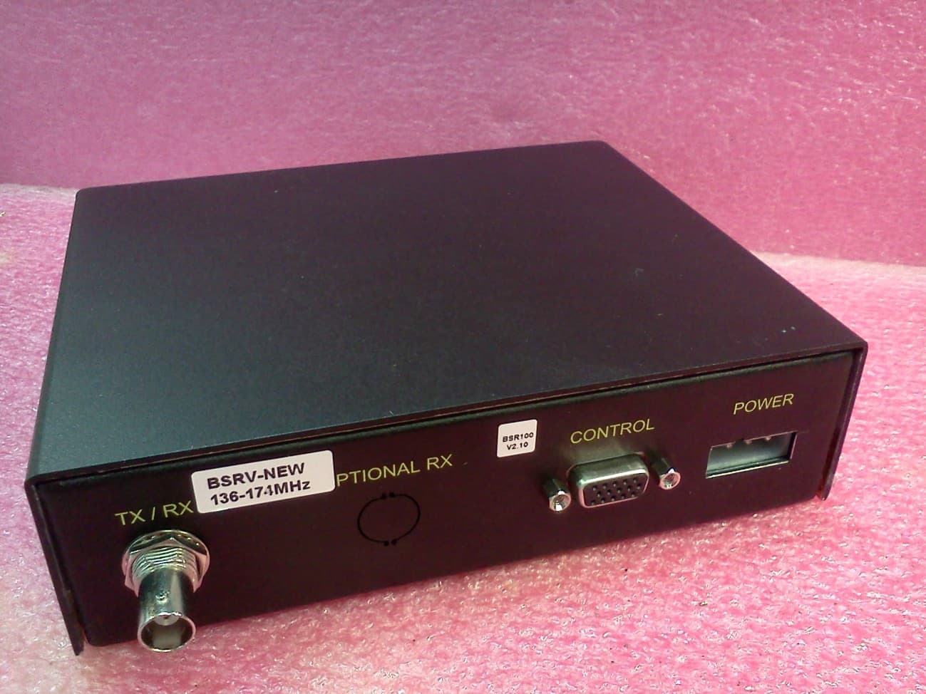
H78KPBSR100N
Sep 26, 2012BASE STATION RADIO
Equipment Class
TNB - Licensed Non-Broadcast Station Transmitter