H78KPMTPITTRANSMITTER FOR WATER METER
KP Electronic Systems Ltd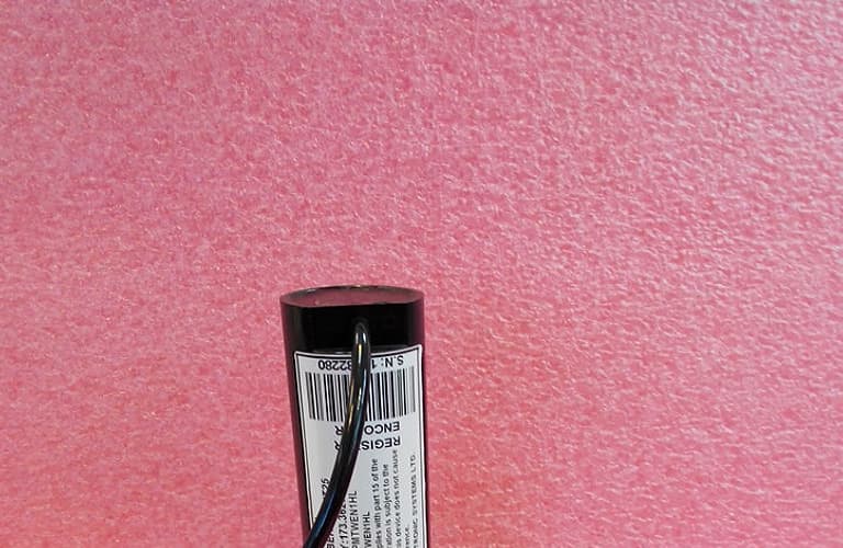
Click to zoom
Application Details
- Equipment Class
- TNB - Licensed Non-Broadcast Station Transmitter
- Date of Grant
- Apr 01, 2015
- Application Purpose
- Original Equipment
- Date of Application
- Apr 01, 2015
- Equipment Note
- TRANSMITTER FOR WATER METER
- Frequency Range
- 172.50000000 - 173.50000000
- Company
- KP Electronic Systems Ltd
- Country
- Israel
Documents & Files
Document Text
Text extracted from the exhibit documents filed with the FCC. Open a document above to read the original.
Users Manual
MTPIT Installation Manual 1. General Description: The MTPIT is for PIT installation. Before installation check if you have all the MTPIT parts: 1. The mushroom shape plastic. Check that the unit is not damaged e.g. there are no scratches or Cracks. 2. Metal washer. 3. Plastic Nut. 4. Cable with NICOR connector. Check the connector pins are straight. 5. Check if there is enough space for the unit beneath the PIT cover. 2. Unit installation 1. Remove and separate the metal washer and the Nut from the mushroom. 2. Insert the mushroom through the cover hole, first the cable. 3. Screw the Nut with the metal washer above. Tied the Nut not too much – just be sure that mushroom is tied to the pit cover. 4. Place the cover on the pit carefully and verify that nothing touches it. 5. Remove the pit cover and place it on the upper cover side so the mushroom i.e. ups down. 6. Connect the cable with the meter cable. Make sure that the two connector ration before pushing one in the other. 7. Place the lid back and cover the pit. 3. PDA using The MTPIT is sealed without any visual indication e.g. LED. The unit functionality should be inspected before leaving the pit site. The MTPIT is in a very low energy. To wake up the unit for testing a magnet should be approach the upper side on the unit from the outside. The MTPIT wakes for shot time waiting from a wireless prompt from the PDA. 4. PDA setting. Com Port - To choose the right RSINT05 port. HH ID - To choose the PDA ID (Paring communication). Set Field Verification 1 Frequency - To choose the first repeaters frequency. Set Field Verification 2 Frequency - To choose the second repeaters frequency. Set Read Meter Frequency - To choose the meter frequency. Use Sound – Turn on/off sound on received message. Field Verification (Receive messages from repeaters): Filter - Set filter (to receive certain address \ receive a range of addresses \ receive all messages the on the air). Clear Screen – Delete received messages from the screen. 5. Programming: MTWE – For programming encoder transmitters. MT1W - For programming MT1W transmitters. MTWP - For programming Pulse transmitters. Meter Protocols – Show all meters protocols. Read Meter (Receive messages directly from the transmitters): Filter - Set filter (to receive certain address \ receive a range of addresses \ receive all messages the on the air). Clear Screen – Delete received messages from the screen. Toggle (Switch between screens): Field Verification 1 - Displays the incoming messages that received on first Frequency. Field Verification 2 - Displays the incoming messages that received on second Frequency. Read Meter - Displays the incoming messages that received on meters frequency. Programming (For transmitters reading and programming): The top of the screen shows the type of transmitter, version and its parameters The lower part of the screen is for programming. Read - Read parameters from the transmitter. Program - Programming new parameters in the transmitter. Test - Transmit Test message (VHF/UHF). Disconnect - End Communications.
RF Exposure Info
RF Exposure Evaluation Report APPLICANT KP ELECTRONIC SYSTEMS LTD. P.O. BOX 42 TEFEN INDUSTRIAL PARK 24959 ISRAEL FCC ID H78KPMTWEN1HL MODEL NUMBER MT150W PRODUCT DESCRIPTION TRANSMITTER FOR WATER METER STANDARD APPLIED CFR 47 Part 2.1091 PREPARED BY Sid Sanders We, TIMCO ENGINEERING, INC. would like to declare that the device has been evaluated in accordance with 47 CFR Part 2.1091 and meets the requirements. The attached report shall not be reproduced except in full without the written approval of TIMCO ENGINEERING, INC. 849 NW STATE ROAD 45 NEWBERRY, FL 32669 USA PH: 888.472.2424 OR 352.472.5500 FAX: 352.472.2030 EMAIL: [email protected] HTTP://WWW.TIMCOENGR.COM Applicant: KP ELECTRONIC SYSTEMS LTD. FCC ID: H78KPMTWEN1HL Report: K\KP H78\335AUT15\335AUT15TestReport.docxt Page 2 of 4 GENERAL REMARKS Attestations This equipment has been evaluated in accordance with the standards identified in this report. To the best of my knowledge and belief, these evaluations were performed using the procedures described in this report. I attest that the necessary evaluations were made, under my supervision, at: Timco Engineering Inc. 849 NW State Road 45 Newberry, Fl 32669 Authorized Signatory Name: Sid Sanders Engineering Project Manager Date: 2/24/2015 RF Exposure Requirements General information Device type: TRANSMITTER FOR WATER METER Devices that operate under Part 90 of this chapter are subject to RF exposure evaluation prior to equipment authorization or use. Antenna The EUT uses a integral antenna, there are no other antenna configurations made available from the manufacturer. Configuration Antenna p/n Type Max. Gain (dBi) Integrated N/A PCB Trace NA (1) Notes: 1. The antenna used is integrated into the device, the output power was measured as ERP, therefore the antenna gain is not applicable. Operating configuration and exposure conditions: The conducted output power is shown in the table below. Typical use qualifies for a maximum duty cycle factor of 50%. MPE Calculation: The minimum separation distance is calculated as follows: The limit for general uncontrolled exposure environment is shown in FCC rule Part 1.11310, Table 1. Applicant: KP ELECTRONIC SYSTEMS LTD. FCC ID: H78KPMTWEN1HL Report: K\KP H78\335AUT15\335AUT15TestReport.docx Max Power 2 WequalsMax Power 2000 mW Duty Cycle50 %equals Duty Factor0.5numeric Antenna Gain 0 dBi equalsGain numeric 1 numeric Coax Loss0 dBGain - Coax Loss1 numeric Power Density 0.2 mW/cm 2 Frequency173.5 MHz Frequency rangPower denEnter this value MHz mW/cm 2 mW/cm 2 0.3-1.34100 100 1.34-30 180/f 2 0.0 30-3000.2 0.2 300-1,500f/15000.1 1,500-100,0001 1 f = frequency in MHz Minimum Separation Distance 20cm0.20 m Minimum Seperation in Inches 7.847195Inches Minimum Separation Distance for Mobile or Fixed Devices General Population/Uncontrolled Exposure Insert values in yellow highlighted boxes to determine Minimum Separation Distance Enter power Density from the chart to the rightRule Part 1.1310, Table 1
Test Report
FCC VHF PORTABLE PART 90 TEST REPORT APPLICANT KP ELECTRONIC SYSTEMS LTD. P.O. BOX 42 TEFEN INDUSTRIAL PARK 24959 ISRAEL FCC ID H78KPMTPIT MODEL NUMBER MTPIT25 PRODUCT DESCRIPTION TRANSMITTER FOR WATER METER STANDARD APPLIED CFR 47 Part 90 DATE SAMPLE RECEIVED 2/10/2015 DATE TESTED 23 February 2015 REPORT ISSUE DATE 24 February 2015 TESTED BY Sid Sanders APPROVED BY Cory Leverett TEST RESULTS PASS FAIL Report Number Version Number Description Issue Date 335AUT15TestReport Rev.1 Initial Issue 2/25/15 THE ATTACHED REPORT SHALL NOT BE REPRODUCED EXCEPT IN FULL WITHOUT THE WRITTEN APPROVAL OF TIMCO ENGINEERING, INC. 849 NW STATE ROAD 45 NEWBERRY, FL 32669 USA PH: 888.472.2424 OR 352.472.5500 FAX: 352.472.2030 EMAIL: [email protected] HTTP://WWW.TIMCOENGR.COM Applicant: KP ELECTRONIC SYSTEMS LTD. FCC ID: H78KPMTPIT Report: K\KP H78\335AUT15\335AUT15TestReport.docx Page 2 of 19 TABLE OF CONTENTS GENERAL REMARKS ........................................................................................ 3 GENERAL INFORMATION ................................................................................. 4 TEST REPORT SUMMARY ................................................................................. 5 TEST PROCEDURE .......................................................................................... 6 RF POWER OUTPUT ........................................................................................ 7 MODULATION CHARACTERISTICS .................................................................... 8 OCCUPIED BANDWIDTH .................................................................................. 8 OCCUPIED BANDWIDTH PLOTS: ANALOG 5k2F3E .............................................. 9 SPURIOUS EMISSIONS AT ANTENNA TERMINALS (CONDUCTED) ....................... 10 SPURIOUS EMISSIONS AT ANTENNA TERMINALS (CONDUCTED) ....................... 11 FIELD STRENGTH OF SPURIOUS EMISSIONS ................................................... 12 FIELD STRENGTH OF SPURIOUS EMISSIONS (Cont.) ........................................ 13 FREQUENCY STABILITY ................................................................................. 14 TRANSIENT FREQUENCY BEHAVIOR ............................................................... 15 TRANSIENT FREQUENCY BEHAVIOR ............................................................... 16 TRANSIENT FREQUENCY BEHAVIOR ............................................................... 17 TRANSIENT FREQUENCY BEHAVIOR ............................................................... 18 EQUIPMENT LIST ......................................................................................... 19 Applicant: KP ELECTRONIC SYSTEMS LTD. FCC ID: H78KPMTPIT Report: K\KP H78\335AUT15\335AUT15TestReport.docx Page 3 of 19 GENERAL REMARKS The attached report shall not be reproduced except in full without the written permission of Timco Engineering Inc. Summary The device under test does: fulfill the general approval requirements as identified in this test report not fulfill the general approval requirements as identified in this test report Attestations This equipment has been tested in accordance with the standards identified in this test report. To the best of my knowledge and belief, these tests were performed using the measurement procedures described in this report. All instrumentation and accessories used to test products for compliance to the indicated standards are calibrated regularly in accordance with ISO 17025: 2005 requirements. I attest that the necessary measurements were made, under my supervision, at: Timco Engineering Inc. 849 NW State Road 45 Newberry, Fl 32669 Authorized Signatory Name: Engineering Project Manager Date: 23 February 2015 Table of Contents Applicant: KP ELECTRONIC SYSTEMS LTD. FCC ID: H78KPMTPIT Report: K\KP H78\335AUT15\335AUT15TestReport.docx Page 4 of 19 GENERAL INFORMATION EUT Specification EUT Description TRANSMITTER FOR WATER METER FCC ID H78KPMTPIT Model Number MTPIT25 Operating Frequency Range 172.5 – 173.5 MHz Test Frequencies 173.000MHz, Type of Emission 1K90F1D Modulation FM EUT Power Source 110–120Vac/50– 60Hz DC Power 6.0V Battery Operated Exclusively Test Item Prototype Pre-Production Production Type of Equipment Fixed Mobile Portable Test Conditions The temperature was 24-26ºC with a relative humidity of 50-65%. Revision History to the EUT None Test Exercise The EUT was placed in continuous transmit mode. Applicable Standards ANSI/TIA 603-D:2010, FCC CFR 47 Part 90 Test Facility Timco Engineering Inc. 849 NW State Road 45 Newberry, FL 32669 USA. Table of Contents Applicant: KP ELECTRONIC SYSTEMS LTD. FCC ID: H78KPMTPIT Report: K\KP H78\335AUT15\335AUT15TestReport.docx Page 5 of 19 TEST REPORT SUMMARY Rule Part No. Scope of Work Status Pass/Fail/NA Part 2.1033(c)(8), Part 2.1046(a), Part 90 RF Power Output PASS Part 2.1033(c) (4) Part 2.1047(a)(6) Modulation Characteristics NA 2.1049(c), 90.210(b), 90.210 (c) 90.210(d), 90.210(e) Emission Mask and Occupied Bandwidths PASS 2.1051(a) Antenna Conducted Emissions PASS 2.1053, Part 90 Field Strength Spurious Emissions PASS Part 2.1055, Part 90.213 Frequency Stability PASS Part 90.214 Transient Frequency Behavior PASS Table of Contents Applicant: KP ELECTRONIC SYSTEMS LTD. FCC ID: H78KPMTPIT Report: K\KP H78\335AUT15\335AUT15TestReport.docx Page 6 of 19 TEST PROCEDURE Power Line Conducted Interference: The procedure used was ANSI/TIA 603- D:2010, using a 50uH LISN. Both lines were observed with the EUT transmitting. The bandwidth of the spectrum analyzer was 10 kHz with an appropriate sweep speed. Bandwidth 20 dB: The measurements were made with the spectrum analyzer's resolution bandwidth (RBW) = 1 MHz and the video bandwidth (VBW) = 3 MHz and the span set as shown on plot. Power Output: The RF power output was measured at the antenna feed point using a peak power meter. Antenna Conducted Emissions: The RBW = 100 kHz, VBW = 300 kHz and the span set to 10.0 MHz and the spectrum was scann…
Text truncated - open the document above for the full version.
Test Setup Photos
APPLICANT: KP ELECTRONIC SYSTEMS LTD. FCC ID: H78KPMTPIT TEST SET UP PHOTO
Contact Information
Applicant
Yoram Kenig
Technical Contact
Timco Engineering, Inc.Sid Sanders
[email protected]888-472-2424
849 NW State Road 45 · Newberry, Florida · United States
Non-Technical Contact
Timco Engineering, Inc.Sharon Hoffman
[email protected]888-472-2424
Test Firm
Timco Engineering, Inc.Bruno Clavier
Technical Specifications
| # | Rule Parts | Frequency Range | Power Output | Emission | Tolerance |
|---|---|---|---|---|---|
| 1 | 90 | 172.5 MHz - 173.5 MHz | 2 W | 1K90F1D | 0.4620000000 ppm |
Other Applications from KP Electronic Systems Ltd

H78KPMT2W-MK
Sep 21, 2020UHF Automatic Meter Reading transceiver
Equipment Class
TNB - Licensed Non-Broadcast Station Transmitter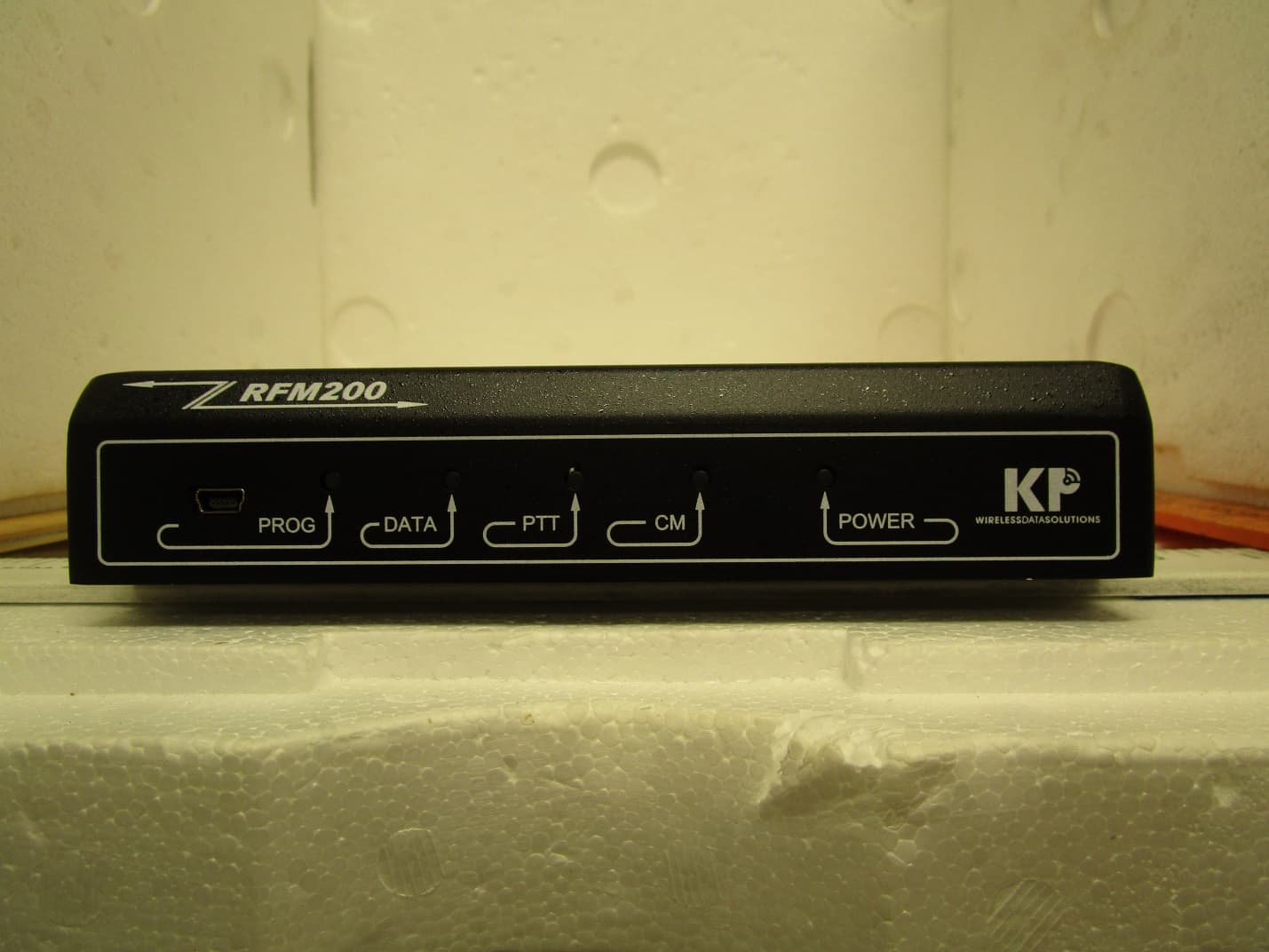
H78KPRFM200U
Apr 15, 2020BASE STATION TRANSCEIVER
Equipment Class
TNB - Licensed Non-Broadcast Station Transmitter
H78KPMT2W
Oct 25, 2015VHF Automatic Meter Reading Transceiver with 2.4 GHz TX
Equipment Class
TNB - Licensed Non-Broadcast Station Transmitter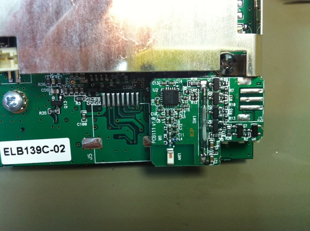
H78KPELB160PIT
Jan 29, 20132.4GHz MODULE
Equipment Class
DXX - Part 15 Low Power Communication Device Transmitter
H78KPBSR100N
Sep 26, 2012BASE STATION RADIO
Equipment Class
TNB - Licensed Non-Broadcast Station Transmitter