H9PAP5131SSymbol WLAN 802.11abg Access Point
Symbol Technologies Inc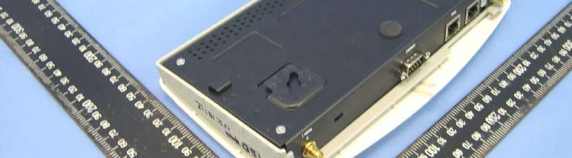
Click to zoom
Application Details
- Equipment Class
- NII - Unlicensed National Information Infrastructure TX
- Date of Grant
- Oct 06, 2005
- Application Purpose
- Original Equipment
- Date of Application
- Oct 06, 2005
- Equipment Note
- Symbol WLAN 802.11abg Access Point
- Frequency Range
- 5180.00000000 - 5320.00000000
- Company
- Symbol Technologies Inc
- Country
- United States
Documents & Files
Document Text
Text extracted from the exhibit documents filed with the FCC. Open a document above to read the original.
Users Manual
AP-5131 Access Point INSTALLATION GUIDE © 2001-2005 by Symbol Technologies, Inc. All rights reserved. No part of this publication may be modified or adapted in any way, for any purposes without permission in writing from Symbol Technologies, Inc. (Symbol). The material in this manual is subject to change without notice. Symbol reserves the right to make changes to any product to improve reliability, function, or design. No license is granted, either expressly or by implication, estoppels, or otherwise under any Symbol Technologies, Inc., intellectual property rights. An implied license only exists for equipment, circuits and subsystems contained in Symbol products. Symbol and the Symbol logo are registered trademarks of Symbol Technologies, Inc. Patents This product is covered by one or more of the U.S. and foreign patents listed at: http://www.symbol.com/patents Symbol Technologies, Inc. One Symbol Plaza Holtsville, New York 11742-1300 http://www.symbol.com Contents 1.0 Introduction . . . . . . . . . . . . . . . . . . . . . . . . . . . . . . . . . . . . . . . . . 1 1.1 Document Conventions . . . . . . . . . . . . . . . . . . . . . . . . . . . . . . . . . . 1 1.2 Warnings . . . . . . . . . . . . . . . . . . . . . . . . . . . . . . . . . . . . . . . . . . . . . 2 1.3 Site Preparation . . . . . . . . . . . . . . . . . . . . . . . . . . . . . . . . . . . . . . . 2 2.0 AP-5131 Specifications . . . . . . . . . . . . . . . . . . . . . . . . . . . . . . . 3 2.1 Physical Characteristics . . . . . . . . . . . . . . . . . . . . . . . . . . . . . . . . . 3 2.2 Electrical Characteristics . . . . . . . . . . . . . . . . . . . . . . . . . . . . . . . . 3 2.3 Radio Characteristics . . . . . . . . . . . . . . . . . . . . . . . . . . . . . . . . . . . 4 3.0 Hardware Installation . . . . . . . . . . . . . . . . . . . . . . . . . . . . . . . . . 5 3.1 Precautions. . . . . . . . . . . . . . . . . . . . . . . . . . . . . . . . . . . . . . . . . . . . 5 3.2 Package Contents . . . . . . . . . . . . . . . . . . . . . . . . . . . . . . . . . . . . . . 5 3.3 AP-5131 Placement . . . . . . . . . . . . . . . . . . . . . . . . . . . . . . . . . . . . . 6 AP-5131 Install Guide 3.4 Mounting the AP-5131 . . . . . . . . . . . . . . . . . . . . . . . . . . . . . . . . . 11 3.5 LED Indicators . . . . . . . . . . . . . . . . . . . . . . . . . . . . . . . . . . . . . . . . 21 4.0 Basic AP-5131 Configuration . . . . . . . . . . . . . . . . . . . . . . . . . 22 4.1 Configuring Basic AP-5131 Device Settings . . . . . . . . . . . . . . . . . 25 4.2 Where to Go From Here? . . . . . . . . . . . . . . . . . . . . . . . . . . . . . . . 34 5.0 Regulatory Compliance . . . . . . . . . . . . . . . . . . . . . . . . . . . . . . 35 6.0 Waste Electrical and Electronic Equipment (WEEE) . . . . . 39 7.0 Support and Sales . . . . . . . . . . . . . . . . . . . . . . . . . . . . . . . . . . . 41 Introduction 1 1Introduction The Symbol AP-5131 Access Point (AP) provides a bridge between Ethernet wired LANs or WANs and wireless networks. It provides connectivity between Ethernet wired networks and radio-equipped mobile units (MUs). MUs include the full line of Symbol terminals, bar-code scanners adapters (PC cards, Compact Flash cards and PCI adapters) and other devices. The AP-5131 provides a maximum 54Mbps data transfer rate via each radio. It monitors Ethernet traffic and forwards appropriate Ethernet messages to MUs over the network. It also monitors MU radio traffic and forwards MU packets to the Ethernet LAN. The AP-5131 is available in two radio versions, a single-radio and dual-radio model. One version of the device firmware runs on the AP-5131 regardless of its radio configuration. The Symbol AP-5131 Access Point is available in the following base models: •Single 802.11a/g radio, external antenna (Part No. AP-5131-4002X-WW) •Dual 802.11a+g radio, external antenna (Part No. AP-5131-1304X-WW) If new to the AP-5131 and access point technology, refer to the AP-5131 Product Reference Guide to familiarize yourself with access point technology and the feature set exclusive to the Symbol AP-5131. The guide is on the CD-ROM shipped with the AP-5131, or can be found at (http://www.symbol.com/services/downloads.html ). 1.1 Document Conventions The following graphical alerts are used in this document to indicate notable situations: NOTETips, hints, or special requirements that you should take note of. CAUTIONCare is required. Disregarding a caution can result in data loss or equipment malfunction. WARNING!Indicates a condition or procedure that could result in personal injury or equipment damage. ! AP-5131 Access Point: Installation Guide 2 1.2 Warnings •Read all installation instructions and site survey reports, and verify correct equipment installation before connecting the AP-5131 to its power source. •Remove jewelry and watches before installing this equipment. •Verify that the unit is grounded before connecting it to the power source. •Verify that any device connected to this unit is properly wired and grounded. •Connect all power cords to a properly wired and grounded electrical circuit. •Verify that the electrical circuits have appropriate overload protection. •Attach only approved power cords to the device. •Verify that the power connector and socket are accessible at all times during the operation of the equipment. •Do not work with power circuits in dimly lit spaces. •Do not install this equipment or work with its power circuits during thunderstorms or other weather conditions that could cause a power surge. •Verify there is adequate ventilation around the device, and that ambient temperatures meet equipment operation specifications. 1.3 Site Preparation •Consult your site survey and network analysis reports to determine specific equipment placement, power drops, and so on. •Assign installation responsibility to the appropriate personnel. •Identify and document where all installed components are located. •Provide a sufficient number of pow…
Text truncated - open the document above for the full version.
Cover Letter(s)
TCB QUESTION 2: From: steve.cheng [mailto:[email protected]] Sent: 05 October 2005 08:21 To: Belli, Marco Cc: [email protected] Subject: RE: RE: RE: Symbol AP5131 FCC and IC statement issue Hi Marco, I have reviewed the supplied documents and am not able to find the evidence which can support the grant condition that Symbol has reached with FCC as listed below. The following conditions are used by Symbol and met with the FCC's approval: 1. Configuration of the System is by a trained installer and requires password access. <Steve> Although, page 23 show the EUT has the password control scheme, however, in page 24 “section 3.1.1 Resetting the AP-5131 Password” supply the way to breach this security function too. Please confirm how this scheme can meet FCC’s requirement? 2. There are warning screens displayed when the system is being configured. <Steve> Okay, information found in page 24. 3. The end 'User' has no access to the System configuration. <Steve> True only if item 1 could be approved. Best regards, Steve Cheng CKC certification services SYMBOL RESPONSE 2 From: Belli, Marco [[email protected]] 寄件日期: 2005年10月5日星期三 上午 3:44 To: steve.cheng CC: [email protected] RE: Symbol AP5131 FCC and IC statement issue Hello Steve Again - this Access Point is part of a professional installation and once installed they are placed in strategic locations, to give best coverage (on walls / above the ceiling space).....The reset screen is not available over the LAN connection, so not accessible to the 'end user'. It should also be considered that the access point must be completely reconfigured by this process, so again a trained installer must carry out this procedure. SYMBOL RESPONSE -----Original Message----- From: Belli, Marco [mailto:[email protected]] Sent: Wednesday, September 28, 2005 1:06 PM To: steve.cheng; [email protected] Cc: [email protected]; [email protected]; Kostelz, John; Narnor, Dornu; Luksich, Mark; Clark, Randy Subject: RE: RE: RE: Symbol AP5131 FCC and IC statement issue Let me address each of the points in turn: 1.FCC Symbol addressed this issue directly with the FCC, Following the FCC query to the ITI Trade Association on the ability of consumers to select and configure Wi-Fi access points outside the authorized band. Symbol (Dornu Narnor and Mark Luksich) met with the FCC (Rich Fabina, Rashmi Doshi, and Tim Harrington) to discuss this issue. At the meeting, Symbol demonstrated a Symbol Access Point and the set-up process. The following conditions are used by Symbol and met with the FCC's approval: 1. Configuration of the System is by a trained installer and requires password access. 2. There are warning screens displayed when the system is being configured. 3. The end 'User' has no access to the System configuration. This type of product is targeted at the INDUSTRIAL USER and is not to the consumer market through outlets such as KMART and Best Buy. As a final note the conditions described above has been implemented in all Symbol infrastructure products which have been FCC approved over the past couple of years. I assume this evidence data will allow you progress this application - Please confirm TCB QUESTION 1: From: [email protected] [mailto:[email protected]] Sent: 28 September 2005 10:32 To: Belli, Marco Subject: 回信: RE: RE: Symbol AP5131 FCC 1. There is a serious problem with this product that it allow end-user to change the regulatory domain (I understand that Symbol has already clearly warned the user that they show select correct country code to avoid violates the law. But unfortunately FCC ’s policy is not allowing this function in all US model.) See TCB training note below: TCB conference call 2003/07/08 by Rich Fabina 1. USER SELECTABLE FREQUENCIES BY COUNTRY At this time, the FCC will not authorize transmitters that have the capability to allow the end user to choose various frequency bands that may be valid for other countries but are not in accordance with the frequency bands permitted by the FCC rules for use in the USA. This includes transmitters that use active or passive listening techniques on these non-USA frequencies. These transmitters must have these end user options disabled. Section 15.15(b) prohibits adjustments of any control by the user that will cause operation of a device in violation of the regulations. Accordingly, any proposal to allow the end user to choose extended channels on frequencies outside of an allowable frequency band in the USA is not acceptable. For example, a WLAN device operating according to Section 15.247 on channels 1-11 between 2.4 - 2.483.5 GHz must not have any user controls or software to allow the device to operate on channels 12 and 13 which are outside of the allowed USA band. This issue may be addressed in a future rulemaking. Steve Cheng CKC Certification Services
External Photos
Page 1 CONSTRUCTION PHOTOS OF EUT EUT with Antenna: ML-2452-APA2-01 Page 2 EUT with Antenna: ML-2499-11PNA2-01 Page 3 EUT with Antenna: ML-2499-HPA3-01 Page 4 EUT with Antenna: ML-2499-BYGA2-01 Page 5 EUT with Antenna: ML-5299-WPNA1-01 Page 6 EUT with Antenna: ML-5299-HPA1-01 Page 7 Page 8
ID Label/Location Info
FCC ID: H9PAP5131S FCC LABEL LOCATION The label will be permanently affixed at a conspicuous location on the device. Label
Internal Photos
Page 9 Page 10 Page 11 Page 12 Page 13 Page 14 Page 15 Page 16 Page 17 Page 18 Page 19 Antenna: ML-2452-APA2-01 Page 20 Antenna: ML-2499-11PNA2-01 Page 21 Page 22 Antenna: ML-2499-HPA3-01 Page 23 Page 24 Antenna: ML-2499-BYGA2-01 Page 25 Page 26 Page 27 Page 28 Page 29 Page 30 Page 31 Page 32 Antenna: ML-5299-WPNA1-01 Page 33 Page 34 Antenna: ML-5299-HPA1-01 Page 35 Page 36 Adapter Page 37 Page 38
RF Exposure Info
FCC ID: H9PAP5131S Report No.: SA 940816H031Issued: Sep. 22, 2005 RF EXPOSURE REPORT REPORT NO.: SA940816H03 MODEL NO.: AP-5131 PART NO.: AP-5131-40000-WW ACCORDING: FCC Guidelines for Human Exposure IEEE C95.1 APPLICANT: Symbol Technologies Inc. ADDRESS: One Symbol Plaza, Holtsville, NY 11742- 1300 U.S.A. ISSUED BY: Advance Data Technology Corporation LAB LOCATION: No. 81-1, Lu Liao Keng, 9 Ling, Wu Lung Tsuen, Chiung Lin Hsiang, Hsin Chu Hsien, Taiwan, R.O.C. FCC ID: H9PAP5131S Report No.: SA 940816H032Issued: Sep. 22, 2005 RF Exposure Measurement 1. Introduction In this document, we try to prove the safety of radiation harmfulness to the human body for our product. The limit for Maximum Permissible Exposure (MPE) specified in FCC 1.1310 is followed. The Gain of the antenna used in this product is measured in a Fully Anechoic Chamber (FAC) calibrated for antenna measurement in ADT, and also the maximum total power input to the antenna is measured. Through the Friis transmission formula and the maximum gain of the antenna, we can calculate the distance, away from the product, where the limit of MPE is reached. Although the Friis transmission formula is a far field assumption, the calculated result of that is an over-prediction for near field power density. We will take that as the worst case to specify the safety range. 2. RF Exposure Limit According to FCC 1.1310: The criteria listed in the following table shall be used to evaluate the environmental impact of human exposure to radio-frequency (RF) radiation as specified in 1.1307(b) LIMITS FOR MAXIMUM PERMISSIBLE EXPOSURE (MPE) Frequency Range (MHz) Electric Field Strength (V/m) Magnetic Field Strength (A/m) Power Density (mW/cm 2 ) Average Time (minutes) (A)Limits For Occupational / Control Exposures 300-1500......F/3006 1500-100,000......56 (B)Limits For General Population / Uncontrolled Exposure 300-1500......F/15006 1500-100,000......1.030 F = Frequency in MHz FCC ID: H9PAP5131S Report No.: SA 940816H033Issued: Sep. 22, 2005 3. Friis Formula Friis transmission formula : Pd = (Pout*G) / (4*pi*r 2 ) where Pd = power density in mW/cm 2 Pout = output power to antenna in mW G = gain of antenna in linear scale Pi = 3.1416 R = distance between observation point and center of the radiator in cm Pd is the limit of MPE, 1 mW/cm 2 . If we know the maximum Gain of the antenna and the total power input to the antenna, through the calculation, we will know the MPE value at distance 20cm. Ref. : David K. Cheng, Field and Wave Electromagnetics, Second Edition, Page 640, Eq. (11-133). 4 EUT Operating condition The software provided by Manufacturer enabled the EUT to transmit and receive data at lowest, middle and highest channel individually. 5. Classification This is a stand alone radio device. So under normal use condition, it is easy to be re- located in the place where at least 20 cm far away from the body of the user. Warning statement to the user for keeping at least 20cm or more separation distance with the antenna should be included in users manual. So, this device is classified as Mobile Device. FCC ID: H9PAP5131S Report No.: SA 940816H034Issued: Sep. 22, 2005 6 Test Results 6.1 Antenna Gain For 2.4GHz Antenna 1: The maximum Gain of the antenna is 3.0dBi. Antenna 2: The maximum Gain of the antenna with cable and extend cable loss is 11.0dBi. Antenna 3: The maximum Gain of the antenna with cable and extend cable loss is 2.8dBi. Antenna 4: The maximum Gain of the antenna with cable, extend cable and Arrestor loss is 12.4dBi. For 5GHz Antenna 1: The maximum Gain of the antenna is 4.0dBi. Antenna 2: The maximum Gain of the antenna with cable loss is 13.0dBi. Antenna 3: The maximum Gain of the antenna with cable loss is 5.0dBi. For 2.4GHz No.Symbol P/NGain (dBi) Cable Loss (dB) Net Gain (dB) Antenna TypeConnectorRemark 1*ML-2452-APA2-013.003.0DipoleRP SMAOmni 2ML-2499-11PNA2-0111.22.78.5PanelReverse BNCDirectional 3ML-2499-HPA3-014.61.33.3DipoleReverse BNCOmni 4**ML-2499-BYGA2-0114.20.313.9YagiRP SMADirectional For 5GHz No.Symbol P/NGain (dBi) Cable Loss (dB) Net Gain (dB) Antenna TypeConnectorRemark 1*ML-2452-APA2-014.004.0DipoleRP SMAOmni 2ML-5299-WPNA1-0114.21.213.0PatchRP SMADirectional 3ML-5299-HPA1-015.90.845.0OmniRP SMAOmni Note: 1. All of the above antennas are Indoor Antenna except the Symbol P/N: ML-2499-BYGA2-01. 2. “*’” is a Dual Band antenna can be used in both 2.4GHz and 5GHz. 3. “**’” is an Outdoor Antenna it can only be used in point-to-point applications. 4. For 2.4GHz Antenna No. 2 and 3 were tested with Extend cable (0.5 dB loss). 5. For 2.4GHz Antenna No. 4 was tested with Extend cable (0.5 dB loss) and Arrestor (1.0 dB loss). FCC ID: H9PAP5131S Report No.: SA 940816H035Issued: Sep. 22, 2005 6.2 Output Power Into Antenna & RF Exposure value at distance 20cm: For 2.4GHz 802.11b: Antenna 1 Channel Channel Frequency (MHz) Output Power to Antenna (mW) Power Density (mW/cm 2 ) Limit of Power Density (mW/cm 2 ) 1241276.2079010.0302502611.0 6243795.060479370.0377336771.0 11246245.498806020.0180604731.0 Antenna 2 Channel Channel Frequency (MHz) Output Power to Antenna (mW) Power Density (mW/cm 2 ) Limit of Power Density (mW/cm 2 ) 1241228.054336380.0352151161.0 6243795.060479370.1193243641.0 11246217.060823890.0214155451.0 Antenna 3 Channel Channel Frequency (MHz) Output Power to Antenna (mW) Power Density (mW/cm 2 ) Limit of Power Density (mW/cm 2 ) 1241276.2079010.0288887751.0 6243795.060479370.0360353821.0 11246245.498806020.0172476181.0 Antenna 4 Channel Channel Frequency (MHz) Output Power to Antenna (mW) Power Density (mW/cm 2 ) Limit of Power Density (mW/cm 2 ) 1241217.538805020.0606358021.0 6243795.060479370.3286465891.0 1124628.531001140.0294936911.0 FCC ID: H9PAP5131S Report No.: SA 940816H036Issued: Sep. 22, 2005 802.11g: Antenna 1 Channel Channel Frequency (MHz) Output Power to Antenna (mW) Power Density (mW/cm 2 ) Limit of Power Density (mW/cm 2 ) 1241278.704578970.0312413021.0 62437169.82436520.0674107451.0 11246274.47…
Text truncated - open the document above for the full version.
Test Report
FCC ID: H9PAP5131S Report No.: RF940816H031Report Format Version 2.0.4 FCC TEST REPORT (15.247) REPORT NO.: RF940816H03 MODEL NO.: AP-5131 RECEIVED: Aug. 16, 2005 TESTED: Aug. 16 to Sep. 20, 2005 ISSUED: Sep. 27, 2005 APPLICANT: Symbol Technologies Inc. ADDRESS: One Symbol Plaza, Holtsville, NY 11742- 1300 U.S.A. ISSUED BY: Advance Data Technology Corporation TEST LOCATION: No. 81-1, Lu Liao Keng, 9 Ling, Wu Lung Tsuen, Chiung Lin Hsiang, Hsin Chu Hsien, Taiwan, R.O.C. This test report consists of 201 pages in total. It may be duplicated completely for legal use with the approval of the applicant. It should not be reproduced except in full, without the written approval of our laboratory. The client should not use it to claim product endorsement by CNLA, A2LA or any government agencies. The test results in the report only apply to the tested sample. The test results in this report are traceable to the national or international standards. 0536No. 2177-01 ILAC MRA FCC ID: H9PAP5131S Report No.: RF940816H032Report Format Version 2.0.4 Table of Contents 1.CERTIFICATION....................................................................................................6 2.SUMMARY OF TEST RESULTS............................................................................7 3.GENERAL INFORMATION.....................................................................................9 3.1GENERAL DESCRIPTION OF EUT.......................................................................9 3.2DESCRIPTION OF TEST MODES.......................................................................12 3.2.1TEST MODE APPLICABILITY AND TESTED CHANNEL DETAIL:.......................13 3.3GENERAL DESCRIPTION OF APPLIED STANDARDS.......................................15 3.4DESCRIPTION OF SUPPORT UNITS..................................................................16 3.5CONFIGURATION OF SYSTEM UNDER TEST...................................................17 4.TEST TYPES AND RESULTS (802.11b & g, 2400 ~ 2483.5MHz Band)...............19 4.1CONDUCTED EMISSION MEASUREMENT........................................................19 4.1.1LIMITS OF CONDUCTED EMISSION MEASUREMENT......................................19 4.1.2TEST INSTRUMENTS..........................................................................................19 4.1.3TEST PROCEDURES..........................................................................................20 4.1.4DEVIATION FROM TEST STANDARD.................................................................20 4.1.5TEST SETUP.......................................................................................................21 4.1.6EUT OPERATING CONDITIONS.........................................................................21 4.1.7TEST RESULTS...................................................................................................22 4.2RADIATED EMISSION MEASUREMENT.............................................................26 4.2.1LIMITS OF RADIATED EMISSION MEASUREMENT...........................................26 4.2.2TEST INSTRUMENTS..........................................................................................27 4.2.3TEST PROCEDURES..........................................................................................28 4.2.4DEVIATION FROM TEST STANDARD.................................................................28 4.2.5TEST SETUP.......................................................................................................29 4.2.6EUT OPERATING CONDITIONS.........................................................................29 4.2.7TEST RESULTS (ANTENNA 1)............................................................................30 4.2.8TEST RESULTS (ANTENNA 2)............................................................................38 4.2.9TEST RESULTS (ANTENNA 3)............................................................................46 4.2.10TEST RESULTS (ANTENNA 4)............................................................................54 4.36dB BANDWIDTH MEASUREMENT....................................................................62 4.3.1LIMITS OF 6DB BANDWIDTH MEASUREMENT.................................................62 4.3.2TEST INSTRUMENTS..........................................................................................62 FCC ID: H9PAP5131S Report No.: RF940816H033Report Format Version 2.0.4 4.3.3TEST PROCEDURE.............................................................................................63 4.3.4DEVIATION FROM TEST STANDARD.................................................................63 4.3.5TEST SETUP.......................................................................................................63 4.3.6EUT OPERATING CONDITIONS.........................................................................63 4.3.7TEST RESULTS (ANTENNA 1)............................................................................64 4.3.8TEST RESULTS (ANTENNA 2)............................................................................70 4.3.9TEST RESULTS (ANTENNA 3)............................................................................76 4.3.10TEST RESULTS (ANTENNA 4)............................................................................82 4.4MAXIMUM PEAK OUTPUT POWER....................................................................88 4.4.1LIMITS OF MAXIMUM PEAK OUTPUT POWER MEASUREMENT.....................88 4.4.2INSTRUMENTS....................................................................................................88 4.4.3TEST PROCEDURES..........................................................................................89 4.4.4DEVIATION FROM TEST STANDARD.................................................................89 4.4.5TEST SETUP.......................................................................................................89 4.4.6EUT OPERATING CONDITIONS..................................…
Text truncated - open the document above for the full version.
Test Report
FCC ID: H9PAP5131S Report No.: RF940816H03120Report Format Version 2.0.4 4.6 BAND EDGES MEASUREMENT 4.6.1 LIMITS OF BAND EDGES MEASUREMENT Below –20dB of the highest emission level of operating band (in 1MHz Resolution Bandwidth). 4.6.2 TEST INSTRUMENTS Description & ManufacturerModel No.Serial No.Calibrated Until R&S SPECTRUM ANALYZERFSP40100036Nov. 23, 2005 NOTE: 1.The measurement uncertainty is less than +/- 2.6dB, which is calculated as per the NAMAS document NIS81. This uncertainty represents an expanded uncertainty expressed at approximately the 95% confidence level using a coverage factor of k=2. 2.The calibration interval of the above test instruments is 12 months and the calibrations are traceable to NML/ROC and NIST/USA. 4.6.3 TEST PROCEDURE The transmitter output was connected to the spectrum analyzer via a low lose cable. Set RBW spectrum analyzer to 1 MHz and set VBW spectrum analyzer to 10 Hz with suitable frequency span including 1 MHz bandwidth from band edge. The band edges was measured and recorded. The spectrum plots (Peak RBW=VBW=100kHz ; Average RBW=1MHz, VBW=10Hz) are attached on the following pages. 4.6.4 EUT OPERATING CONDITION Same as Item 4.3.5 FCC ID: H9PAP5131S Report No.: RF940816H03121Report Format Version 2.0.4 4.6.5 TEST RESULTS (ANTENNA 1 – DSSS) The spectrum plots are attached on the following page. D1 line indicates the highest level, D2 line indicates the 20dB offset below D1. It shows compliance with the requirement in part 15.247(C). Note - The delta method is only used up to 2 MHz away from the restricted bandage, The radiated emissions which located in other restricted frequency band, the result, please refer to 4.2. NOTE (Peak): The band edge emission plot of DSSS technique on the following first page show 53.95dB delta between carrier maximum power and local maximum emission in restrict band (2.3900GHz). The emission of carrier strength list in the test result of channel 1 at the item 4.2 is 112.7dBuV/m, so the maximum field strength in restrict band is 112.7-53.95=58.75dBuV/m which is under 74 dBuV/m limit. The band edge emission plot of DSSS technique on the following first page shows 51.48dB delta between carrier maximum power and local maximum emission in restrict band (2.4835GHz). The emission of carrier strength list in the test result of channel 11 at the item 4.2 is 110.2dBuV/m, so the maximum field strength in restrict band is 110.2-51.48=58.72dBuV/m which is under 74 dBuV/m limit. NOTE (Average): The band edge emission plot of DSSS technique on the following second page shows 55.27dB delta between carrier maximum power and local maximum emission in restrict band (2.3900GHz). The emission of carrier strength list in the test result of channel 1 at the item 4.2 is 105.4dBuV/m, so the maximum field strength in restrict band is 105.4-55.27=50.13dBuV/m which is under 54 dBuV/m limit. The band edge emission plot of DSSS technique on the following second page shows 53.72dB delta between carrier maximum power and local maximum emission in restrict band (2.4835GHz). The emission of carrier strength list in the test result of channel 11 at the item 4.2 is 103.1dBuV/m, so the maximum field strength in restrict band is 103.1-53.72=49.38dBuV/m which is under 54 dBuV/m limit. FCC ID: H9PAP5131S Report No.: RF940816H03122Report Format Version 2.0.4 FCC ID: H9PAP5131S Report No.: RF940816H03123Report Format Version 2.0.4 FCC ID: H9PAP5131S Report No.: RF940816H03124Report Format Version 2.0.4 FCC ID: H9PAP5131S Report No.: RF940816H03125Report Format Version 2.0.4 4.6.6 TEST RESULTS (ANTENNA 1 – OFDM) The spectrum plots are attached on the following page. D1 line indicates the highest level, D2 line indicates the 20dB offset below D1. It shows compliance with the requirement in part 15.247(C). Note - The delta method is only used up to 2 MHz away from the restricted bandage, The radiated emissions which located in other restricted frequency band, the result, please refer to 4.2. NOTE (Peak): The band edge emission plot of OFDM technique on the following first page show 48.16dB delta between carrier maximum power and local maximum emission in restrict band (2.3900GHz). The emission of carrier strength list in the test result of channel 1 at the item 4.2 is 108.0dBuV/m, so the maximum field strength in restrict band is 108.0-48.16=59.84dBuV/m which is under 74 dBuV/m limit. The band edge emission plot of OFDM technique on the following first page shows 46.52dB delta between carrier maximum power and local maximum emission in restrict band (2.4835GHz). The emission of carrier strength list in the test result of channel 11 at the item 4.2 is 105.6dBuV/m, so the maximum field strength in restrict band is 105.6-46.52=59.08dBuV/m which is under 74 dBuV/m limit. NOTE (Average): The band edge emission plot of OFDM technique on the following second page shows 48.09dB delta between carrier maximum power and local maximum emission in restrict band (2.3900GHz). The emission of carrier strength list in the test result of channel 1 at the item 4.2 is 99.7dBuV/m, so the maximum field strength in restrict band is 99.7-48.09=51.61dBuV/m which is under 54 dBuV/m limit. The band edge emission plot of OFDM technique on the following second page shows 46.54dB delta between carrier maximum power and local maximum emission in restrict band (2.4835GHz). The emission of carrier strength list in the test result of channel 11 at the item 4.2 is 99.3dBuV/m, so the maximum field strength in restrict band is 99.3-46.54=52.76dBuV/m which is under 54 dBuV/m limit. FCC ID: H9PAP5131S Report No.: RF940816H03126Report Format Version 2.0.4 FCC ID: H9PAP5131S Report No.: RF940816H03127Report Format Version 2.0.4 FCC ID: H9PAP5131S Report No.: RF940816H03128Report Format Version 2.0.4 FCC ID: H9PAP5131S Report No.: RF940816H03129Report Format Version 2.0.4 4.6.7 TEST RESULTS (ANTENNA 2 – DSSS) The spectrum plots are attached on the following page. D1 line indicates the highest level, D2 lin…
Text truncated - open the document above for the full version.
Test Report
FCC ID: H9PAP5131S Report No.: RF940816H031Report Format Version 2.0.4 FCC TEST REPORT (15.407) REPORT NO.: RF940816H03 MODEL NO.: AP-5131 RECEIVED: Aug. 16, 2005 TESTED: Aug. 16 to Sep. 25, 2005 ISSUED: Sep. 27, 2005 APPLICANT: Symbol Technologies Inc. ADDRESS: One Symbol Plaza, Holtsville, NY 11742- 1300 U.S.A. ISSUED BY: Advanc…
Text truncated - open the document above for the full version.
Contact Information
Applicant
Qianlin Zhou(Regulatory Specialist)
Technical Contact
Advance Data Technology CorporationEric Lin
[email protected]886-3-593-5343
81-1 Luliaoken, 9th Lin, Wulung Tsuen Chiunglin · Hsinchu · Taiwan
Non-Technical Contact
Advance Data Technology CorporationEric Lin
[email protected]886-3-593-5343
Test Firm
Bureau Veritas CPS (H.K.) Ltd. Taoyuan BranchRichard Chen
Technical Specifications
| # | Rule Parts | Frequency Range | Power Output |
|---|---|---|---|
| 1 | 15E | 5.18 GHz - 5.32 GHz | 193.00 mW |
Other Applications from Symbol Technologies Inc

H9PCCHUB1
Jun 30, 2015Customer Concierge
Equipment Class
NII - Unlicensed National Information Infrastructure TX
H9PAP7562
May 10, 2015802.11 abgn/ac Access Point
Equipment Class
DTS - Digital Transmission System
H9PTC75AH
Mar 26, 2015Touch Computer
Equipment Class
NII - Unlicensed National Information Infrastructure TX
H9PRA1202
Sep 24, 2014UHF Narrowband Radio Module
Equipment Class
TNB - Licensed Non-Broadcast Station Transmitter
H9PEMG101
Aug 26, 2014802.15.4 Gateway
Equipment Class
DTS - Digital Transmission System