H9PAR4126RFID SYSTEM
Symbol Technologies Inc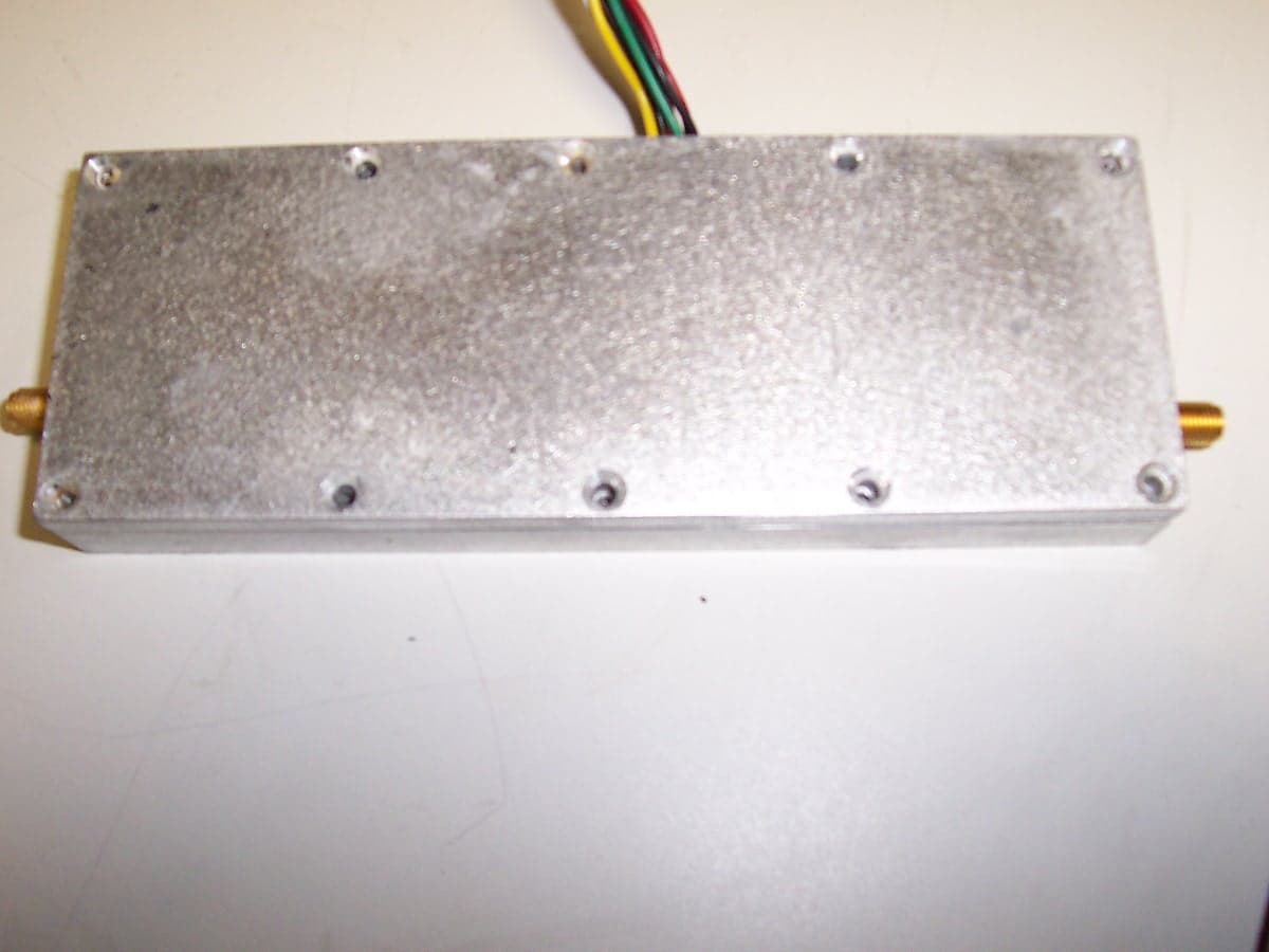
Click to zoom
Application Details
- Equipment Class
- LMS - Part 90 Location & Monitoring Transmitter
- Date of Grant
- May 24, 2005
- Application Purpose
- Original Equipment
- Date of Application
- May 24, 2005
- Equipment Note
- RFID SYSTEM
- Frequency Range
- 910.75000000 - 920.75000000
- Company
- Symbol Technologies Inc
- Country
- United States
Documents & Files
Document Text
Text extracted from the exhibit documents filed with the FCC. Open a document above to read the original.
Users Manual
AR400 RFID Reader Integrator Guide 72E-71810-01 Revision .1 April 2005 © 2005 by Symbol Technologies, Inc. All rights reserved. No part of this publication may be reproduced or used in any form, or by any electrical or mechanical means, without permission in writing from Symbol. This includes electronic or mechanical means, such as photocopying, recording, or information storage and retrieval systems. The material in this manual is subject to change without notice. The software is provided strictly on an “as is” basis. All software, including firmware, furnished to the user is on a licensed basis. Symbol grants to the user a non-transferable and non-exclusive license to use each software or firmware program delivered hereunder (licensed program). Except as noted below, such license may not be assigned, sublicensed, or otherwise transferred by the user without prior written consent of Symbol. No right to copy a licensed program in whole or in part is granted, except as permitted under copyright law. The user shall not modify, merge, or incorporate any form or portion of a licensed program with other program material, create a derivative work from a licensed program, or use a licensed program in a network without written permission from Symbol. The user agrees to maintain Symbol’s copyright notice on the licensed programs delivered hereunder, and to include the same on any authorized copies it makes, in whole or in part. The user agrees not to decompile, disassemble, decode, or reverse engineer any licensed program delivered to the user or any portion thereof. Symbol reserves the right to make changes to any software or product to improve reliability, function, or design. Symbol does not assume any product liability arising out of, or in connection with, the application or use of any product, circuit, or application described herein. No license is granted, either expressly or by implication, estoppel, or otherwise under any Symbol Technologies, Inc., intellectual property rights. An implied license only exists for equipment, circuits, and subsystems contained in Symbol products. Symbol, Spectrum One, and Spectrum24 are registered trademarks of Symbol Technologies, Inc. Bluetooth is a registered trademark of Bluetooth SIG. Microsoft, Windows and ActiveSync are either registered trademarks or trademarks of Microsoft Corporation. Other product names mentioned in this manual may be trademarks or registered trademarks of their respective companies and are hereby acknowledged. Symbol Technologies, Inc. One Symbol Plaza Holtsville, New York 11742-1300 http://www.symbol.com Patents This product is covered by one or more of the patents listed on the website: www.symbol.com/patents Contents About This Guide Introduction ......................................................................................................................... ix Chapter Descriptions ...........................................................................................................ix Notational Conventions ....................................................................................................... ix Related Documents and Software....................................................................................... ix Service Information............................................................................................................... x Symbol Support Center................................................................................................................x Chapter 1. Getting Started Introduction ...................................................................................................................... 1-3 RFID Technology.............................................................................................................. 1-3 RFID Components .....................................................................................................1-3 The AR400 RFID Reader ................................................................................................. 1-4 Multiple Connection Options ...................................................................................... 1-4 Flexible Read Point Configurations............................................................................ 1-4 Configuration and Upgrading ..................................................................................... 1-4 Tag Management .......................................................................................................1-5 Event Management ....................................................................................................1-5 Device Management ..................................................................................................1-5 Security ...................................................................................................................... 1-5 LEDs ................................................................................................................................. 1-6 Chapter 2. Installation and Communication AR400 Physical Connections .......................................................................................... 2-3 Installing the AR400.......................................................................................................... 2-3 Mounting Tips............................................................................................................. 2-3 Mounting the AR400 ..................................................................................................2-4 Connecting Antennas to the AR400...........................................................................2-4 Portal Setup ............................................................................................................... 2-4 Powering the AR400 ..................................................................................................2-4 Verifying Hardware Functionality ......…
Text truncated - open the document above for the full version.
Cover Letter(s)
Regulatory Engineering 20 May 2005 Subject: Stability not required per 90.213 (a) Footnote 13 To the Commission: The transmitter with FCC ID: H9PAR4126 is a non-multilateration system whereby an electronic device placed in a package transfers information from that device when the package passes near one of the system's antennas as such frequency Stability measurement is not required. The transmitter’s emission is more than 40 kHz from the band edge for both the upper and lower band edges; the other requirement per 90.213 (a) Footnote 13. Respectfully, Mark S. Luksich Director, Regulatory Engineering 631-738-5134 [email protected]
Cover Letter(s)
One Symbol Plaza, Holtsville, NY 11742-1300 • 1.631.738.2400 • www.symbol.com Confidentiality request for FCC ID: H9PAR4126 Symbol Technologies Inc. 1 Symbol Plaza Holtsville, NY 11742 Confidentiality Request Pursuant to Sections 0.457(d)(1)(ii) and 0.459 of the Commission’s Rules, Symbol Technologies Inc. hereby requests confidential treatment of information accompanying as outlined below: • Schematics • Block Diagrams • Parts List (Bill of Materials) • Theory of Operation • Antenna Specifications The above materials contain trade secrets and proprietary information not customarily released to the public. The public disclosure of these matters might be harmful to the Applicant and provide unjustified benefits to its competitors. The Applicant understands that pursuant to Rule 0.457(d)(1)(ii), disclosure of this Application and all accompanying materials will not be made before the date of the Grant for this Application. Yours sincerely, Dennis Cortes Symbol Regulatory Compliance Direct Tel: (631) 738-5358 Email: [email protected] Regulatory Engineering • Web Site: http://ww.symbol.com
External Photos
Top View Bottom View Front View Side View Back View
ID Label/Location Info
NOTES: UNLESS OTHERWISE SPECIFIED - Stock: .010 inch thick Polycarbonate,Velvet/Matte, 94-V0, PSA backside. - Finish: 3M#9667MP, .002" Thick. - Artwork to be supplied by Symbol Technologies - Part Number 60-XXXXX-XX. - Package items in accordance with STI general packaging spec #50-04100-013. - Crerated in Illustrator v. 10.0 - Colors: White (flood for opacity), Background to be Symbol DuraGray Max, Copy to Symbol Cash White. - Measurements: 278.68 mm wide x 29.50 mm high. Dura Gray Max Cash White 278.68 276.88 21.12 4X TRUE R2 29.50 FCC ID: H9PAR4126 PART NUMBER/REV SERIAL NUMBER MAC ID: MODEL#: AR4126 Symbol Technologies, Inc. Holtsville, New York, USA Assembled in the USA Telephone: 1.631.738.2400 Power: 24VDC @ 2.1A 301527-001 1/1B SHT. 1 OF 1 JAMES DOWSE AX01 ARTWORK, BACK, FCC, ADV RDR
Internal Photos
Cover Removed Board A Top Board A Bottom
Internal Photos
Board B Bottom
RF Exposure Info
FCC ID: H9PAR4126 RF Exposure Test Report Symbol Technologies Inc. May 2005 Regulatory Engineering • Intranet site: http://wiley.symbol.com/regulatory/index.html Regulatory Engineering Maximum Permissible Exposure Test Report For FCC ID: H9PAR4126 1.0 Introduction This report has been prepared by Symbol Technologies, Inc. FHSS RFID Device to show compliance with the RF exposure requirements as defined in FCC §1.1307. 1.1 Requirements Three different categories of transmitters are defined by the FCC in OET Bulletin 65. These categories are fixed installation, mobile, and portable and are defined as follows: • Fixed Installations: fixed location means that the device, including its antenna, is physically secured at a permanent location and is not able to be easily moved to another location. Additionally, distance to humans from the antenna is maintained to at least 2 meters. • Mobile Devices: a mobile device is defined as a transmitting device designed to be used in other than fixed locations and to be generally used in such a way that a separation distance of at least 20 centimeters is normally maintained between the transmitter's radiating structures and the body of the user or nearby persons. Transmitters designed to be used by consumers or workers that can be easily re-located, such as a wireless modem operating in a laptop computer, are considered mobile devices if they meet the 20 centimeter separation requirement. The FCC rules for evaluating mobile devices for RF compliance are found in 47 CFR §2.1091. • Portable Devices: a portable device is defined as a transmitting device designed to be used so that the radiating structure(s) of the device is/are within 20 centimeters of the body of the user. Portable device requirements are found in Section 2.1093 of the FCC's Rules (47 CFR§2.1093). For this test report the Symbol RFID device with 6dBi antenna is considered a fixed installation as it is used for the purpose of reading tags. The FCC also categorizes the use of the device as based upon the user’s awareness and ability to exercise control over his or her exposure. The two categories defined are Occupational/Controlled Exposure and General Population/Uncontrolled Exposure. These two categories are defined as follows: Regulatory Engineering • Intranet site: http://wiley.symbol.com/regulatory/index.html Occupational/Controlled Exposure: In general, occupational/controlled exposure limits are applicable to situations in which persons are exposed as a consequence of their employment, who have been made fully aware of the potential for exposure and can exercise control over their exposure. This exposure category is also applicable when the exposure is of a transient nature due to incidental passage through a location where the exposure levels may be higher than the general population/uncontrolled limits, but the exposed person is fully aware of the potential for exposure and can exercise control over his or her exposure by leaving the area or by some other appropriate means. Awareness of the potential for RF exposure in a workplace or similar environment can be provided through specific training as part of a RF safety program. If appropriate, warning signs and labels can also be used to establish such awareness by providing prominent information on the risk of potential exposure and instructions on methods to minimize such exposure risks. General Population/Uncontrolled Exposure: The general population / uncontrolled exposure limits are applicable to situations in which the general public may be exposed or in which persons who are exposed as a consequence of their employment may not be made fully aware of the potential for exposure or cannot exercise control over their exposure. Members of the general public would come under this category when exposure is not employment-related; for example, in the case of a wireless transmitter that exposes persons in its vicinity. Warning labels placed on low-power consumer devices such as cellular telephones are not considered sufficient to allow the device to be considered under the occupational/controlled category, and the general population/uncontrolled exposure limits apply to these devices. Since there are no warnings or training associated with this unit and it can be used by anyone, the Symbol RFID device is evaluated to the General Population/Uncontrolled Exposure limits. 1.2 Radio Frequency Radiation Exposure Evaluation The highest RF output power of the unit was measured at 42.7dBm at 920.25 MHz. According to §1.1310 of the FCC rules, the power density limit for General Population/Uncontrolled Exposure at 920.25 MHz is 0.6135mW/cm 2. The MPE is calculated to show the required separation distance that must be maintained during installation to maintain compliance with the power density limit. The following formula was used to calculate the Power Density: Where: S = Power Density P = Output Power at the Antenna Terminals G = Gain of Transmit Antenna (linear gain) R = Distance from Transmitting Antenna Regulatory Engineering • Intranet site: http://wiley.symbol.com/regulatory/index.html To solve for the minimum mounting distance required: For this device, the calculation is as follows: S = 0.6135 mW/cm 2 P = Output Power = 18600 mW G = Worst Case Gain = 6dBi = INVLOG(6/10) = 4 R= (18600) X (4) = 99cm 4 x Π x 0.6135 Based on the above calculation the Symbol AR 400 (Part 90) Reader antenna must be mounted such that it provides a minimum separation distance of 99cm. The User’s Manual addresses the mounting location in the instructions for mounting the reader.
Test Report
Retlif Testing Laboratories Report No.: R-10859-2 APPLICANT Symbol Technologies Inc One Symbol Plaza Holtsville, NY 11742 MANUFACTURER Same As Applicant TEST SPECIFICATION: FCC Rules and Regulations Part 90 TEST PROCEDURE: TIA/EIA-603 TEST SAMPLE DESCRIPTION BRANDNAME: Symbol MODEL: N/A TYPE: RFID Reader POWER REQUIREMENTS: 115 VAC, 60 Hz FREQUENCY OF OPERATION: 910.75 MHz to 920.75 MHz TESTS PERFORMED Para. 90.205(j) TIA/EIA-603;2.2.17, Effective Radiated Power Output Para. 90.210(k)(3) TIA/EIA-603;2.2.12, Spurious Radiated Emissions Para. 90.210(k)(3), Occupied Bandwidth Para. 90.210(k)(3)(ii), Antenna Conducted Emissions Retlif Testing Laboratories Report No.: R-10859-2 FCC Part 90.210(k)(3), Occupied Bandwidth Method Retlif Testing Laboratories Report No.: R-10859-2 FCC Part 90.210(k)(3), Occupied Bandwidth A. Measurement Procedure: The RF output was directly coupled through external attenuators to a spectrum analyzer. The occupied bandwidth of the modulated RF carrier was then recorded and plotted. The modulated signal must be within the template as specified by the applicable paragraph in Part 90; Paragraph 90.210(k)(3), emission mask k. Setup of the test is shown below: B. Test Results: The device complied with the requirements of this test method. See the following three (3) test data sheets for a complete presentation of the test results obtained. Spectrum Analyzer Test Sample Attenuator RF Output Retlif Testing Laboratories Report No.: R-10859-2 EQUIPMENT LIST FCC Part 90.210(k)(3), Occupied Bandwidth EN Type Manufacturer Description Model No. Cal Date Due 068 Attenuator Weinschel DC - 18 GHz 48-30-43 2/3/2004 2/3/2005 141 Spectrum Analyzer Hewlett Packard 100 Hz - 40 GHz 8566B 8/5/2004 2/5/2005 141A Graphics Plotter Hewlett Packard N/A 7470A 2/9/2004 2/9/2005 141B Quasi-Peak Adaptor Hewlett Packard 100 Hz - 1 GHz 85650A 8/7/2004 2/7/2005 831 10 DB Atten. (50 ohm) Narda DC - 11 GHz, 20W 768-10 4/30/2004 4/30/2005 Retlif Testing Laboratories Report No.: R-10859-2 FCC Part 90.210(k)(3), Occupied Bandwidth Test Data Retlif Testing Laboratories Report No.: R-10859-2 FCC Part 90.210(k)(3)(ii), Antenna Conducted Spurious Emissions Method Retlif Testing Laboratories Report No.: R-10859-2 FCC Part 90.210(k)(3)(ii), Antenna Conducted Spurious Emissions A. Measurement Procedure: The RF output of the transmitter was directly coupled through attenuators to the input of a spectrum analyzer. With the transmitter on, the spectrum analyzer was swept from 30 MHz to 9.2 GHz. It was verified that all emissions not associated with the fundamental transmission were at least 55 +10 log (P) down from the fundamental transmit power level (P). Setup of the test is shown below: B. Test Results: The device complied with the requirements of this method. See the following twenty-one (21) test data sheets for a complete presentation of the test results obtained. Spectrum Analyzer Test Sample Attenuator RF Output Retlif Testing Laboratories Report No.: R-10859-2 EQUIPMENT LIST FCC Part 90.210(k)(3)(ii), Antenna Conducted Spurious Emissions EN Type Manufacturer Description Model No. Cal Date Due 068 Attenuator Weinschel DC - 18 GHz 48-30-43 2/3/2004 2/3/2005 141 Spectrum Analyzer Hewlett Packard 100 Hz - 40 GHz 8566B 8/5/2004 2/5/2005 141A Graphics Plotter Hewlett Packard N/A 7470A 2/9/2004 2/9/2005 141B Quasi-Peak Adaptor Hewlett Packard 100 Hz - 1 GHz 85650A 8/7/2004 2/7/2005 723 H.P. Filter Mini-Circuits 1 GHz BHP-1000 7/14/2004 7/14/2005 831 10 DB Atten. (50 ohm) Narda DC - 11 GHz, 20W 768-10 4/30/2004 4/30/2005 Retlif Testing Laboratories Report No.: R-10859-2 FCC Part 90.210(k)(3)(ii), Antenna Conducted Spurious Emissions Test Data Retlif Testing Laboratories Report No.: R-10859-2 TIA/EIA-603;2.2.12 and TIA/EIA-603;2.2.17 Output Power and Field Strength of Spurious Emissions, Effective Radiated Power Method Retlif Testing Laboratories Report No.: R-10859-2 TIA/EIA-603;2.2.12 and TIA/EIA-603;2.2.17 Output Power and Field Strength of Spurious Emissions, Effective Radiated Power Method A. Measurement Procedure: The fundamental and spurious emissions of the transmitter from 30 MHz to 9.2 GHz were measured in accordance with TIA/EIA603, Paragraph 2.2.1.2 as described below: The transmitter under test was placed on an 80-cm high non-metallic table on the Open Air Test Site with its antenna terminated into a shielded load. A receive antenna was placed three meters away from the transmitter. The turntable was rotated 360 degrees and the receive antenna was raised and lowered from 1 to 4 meters until a maximum reading was obtained at each spurious emission detected. This reading was recorded. The transmitter under test was replaced with a dipole (or equivalent antenna) and signal generator. The signal generator was set to the frequency for the spurious emission. The level of the signal generator was increased until the level was equal to that previously measured. The required input level from the signal generator in dBm was recorded and the antenna gain (in dB) of the transmit antenna was added. This was the Effective Radiated Power of the spurious emission. For the Fundamental Power output measurement the shielded load was replaced by the EUT’s standard transmit antenna and the above procedure was repeated at the fundamental transmit frequency. Setup of the test is shown below: A. Test Results: See the following two (2) test data sheets for a complete presentation of the test results obtained. Spectrum Analyzer Test Sample 3M 4M Broadband Antenna Pre Amplifier Retlif Testing Laboratories Report No.: R-10859-2 EQUIPMENT LIST TIA/EIA-603;2.2.12-Spurious Radiated Emissions EN Type Manufacturer Description Model No. Cal Date Due 067 Open Area Test Site Retlif 3 Meter RNY 10/1/2003 10/1/2006 128 Double Ridged Guide Electro-Mechanics 1 GHz - 18 GHz 3105 6/21/2004 6/21/2005 133 Broadband Pre-Amplifier Electro-Metrics 10 kHz - 1 GHz, 26dB BPA-1000 6/12/2004 6/12/2005 141 Spectrum Analyzer Hewlett Packard 100 Hz - 40 GH…
Text truncated - open the document above for the full version.
Contact Information
Applicant
Qianlin Zhou(Regulatory Specialist)
Test Firm
Retlif Testing LaboratoriesMichael Bozza
Technical Specifications
| # | Rule Parts | Frequency Range | Power Output | Emission |
|---|---|---|---|---|
| 1 | 90.353 | 910.75 MHz - 920.75 MHz | 18.6 W | 1M19A2D |
Other Applications from Symbol Technologies Inc

H9PCCHUB1
Jun 30, 2015Customer Concierge
Equipment Class
NII - Unlicensed National Information Infrastructure TX
H9PAP7562
May 10, 2015802.11 abgn/ac Access Point
Equipment Class
DTS - Digital Transmission System
H9PTC75AH
Mar 26, 2015Touch Computer
Equipment Class
NII - Unlicensed National Information Infrastructure TX
H9PRA1202
Sep 24, 2014UHF Narrowband Radio Module
Equipment Class
TNB - Licensed Non-Broadcast Station Transmitter
H9PEMG101
Aug 26, 2014802.15.4 Gateway
Equipment Class
DTS - Digital Transmission System