H9PCST3040K088R1Handheld Portable Shopping System Transmitter
Symbol Technologies Inc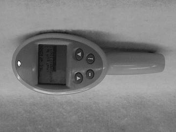
Click to zoom
Application Details
- Equipment Class
- DSS - Part 15 Spread Spectrum Transmitter
- Date of Grant
- Jun 26, 2000
- Application Purpose
- Original Equipment
- Date of Application
- Mar 01, 2000
- Equipment Note
- Handheld Portable Shopping System Transmitter
- Frequency Range
- 2402.00000000 - 2480.00000000
- Company
- Symbol Technologies Inc
- Country
- United States
Documents & Files
Document Text
Text extracted from the exhibit documents filed with the FCC. Open a document above to read the original.
Users Manual
FCC USER’S MANUAL REQUEST To the FCC: The H9PCST3040K088R1 Part 15 Subpart C Certification application is a product that is circuit board electrically identical to our H9PLA24005AZL approval. The H9PLA24005AZL approval was based on a PCMCIA card footprint, for the H9PCST3040K088R1 approval the circuit board was the same but the PCMCIA card enclosure had to be removed so a new Certification was applied for. As stated above the new certification is for a radio that is compatible with Symbol’s 1Mb S24 radio (LA24005AZL). The new radio is to work as part of the Portable Shopping System as outlined in the Installation Guide. Included here is the presently planned Installation Guide. Also included here is a Regulatory Addendum that will be included in the final User’s Guide and the Installation Guide. The regulatory addendum included with this submission will be added to the included Installation Guide and to the final User’s guide. The Regulatory addendum has the FCC CFR 47 Part 15.105 information to the user, FCC CFR 47 Part 15.21 information to user warning against modifying the radio and the RF safety warning. If you have any questions about the above please don’t hesitate to ask. Thank You Sandy Mazzola Symbol Technologies Inc. Regulatory Engineer 1 Symbol Plaza Holtsville, N.Y. 11742-1300 Phone: (631) 738-5373 Fax: (631) 738-3318 E-mail:[email protected]
Users Manual
WaveWorks Portable Shopping System Integration Guide February 1, 2000 Version 1.10 Integration Services Group Pittsburgh, Pennsylvania USA Decembe Revision History RevisionDateAuthorComments 1.00December 31, 1999Mary Wroniak Garry Simmons Brian Reed Tom Pike Mike Tierney Luke Petrozza Initial version 1.10February, 1, 2000Luke PetrozzaAdded PST 008 and PST 038 transactions Copyright 1999, 2000 by Symbol Technologies, Inc. All rights reserved. No part of this document may be reproduced or used in any form, or by any electrical or mechanical means, without permission in writing from Symbol. This includes electronic or mechanical means, such as photocopying, recording, or information storage and retrieval systems The material in this document is subject to change with notice. Symbol does not assume any product liability arising out of, or in connection with, the application or use of any product, circuit, or application described herein. No license is granted, either expressly or by implication, estoppel, or otherwise under any Symbol Technologies, Inc., intellectual property rights. An implied license only exists for equipment, circuits, and subsystems contained in Symbol products. Symbol, Spectrum24, WaveWorks, and WaveWorks NT are registered trademarks of Symbol Technologies, Inc. Other product names mentioned in this document may be trademarks or registered trademarks of their respective companies and are hereby acknowledged. WaveWorks PSS, Integration Guide, 1.10Page ii © 2000, Symbol Technologies, Inc.February 1, 2000 Table of Contents 1.Introduction ............................................................................................................1 1.1PURPOSE OF DOCUMENT................................................................................................................................. 1 1.2A SSUMPTIONS................................................................................................................................................. 1 1.3R EFERENCE DOCUMENTS................................................................................................................................1 2.Architecture Overview ...........................................................................................2 2.1INTRODUCTION TO WAVEWORKS.................................................................................................................... 2 2.1.1WaveWorks Design Objectives.............................................................................................................. 3 2.1.2WaveWorks Components....................................................................................................................... 4 2.2PSS S OFTWARE OVERVIEW............................................................................................................................. 6 2.3M AJOR SUBSYSTEMS....................................................................................................................................... 6 2.3.1Unit Management Subsystem ................................................................................................................ 6 2.3.2Shopping Trip Subsystem ..................................................................................................................... 6 2.3.3Quick Order Subsystem ......................................................................................................................... 7 2.3.4Queue Busting Subsystem...................................................................................................................... 7 2.3.5Express Shopper Subsystem .................................................................................................................. 7 2.3.6Electronic Marketing Subsystem ........................................................................................................... 7 2.3.7User Messaging..................................................................................................................................... 8 2.3.8Transaction Ticket Printing .................................................................................................................. 8 2.3.9POS Interface ........................................................................................................................................ 8 2.3.10System Administration........................................................................................................................... 8 2.4PSS O VERVIEW DIAGRAM.............................................................................................................................. 8 2.5PSS C OMPONENT DIAGRAM.......................................................................................................................... 10 3.Hardware Requirements ......................................................................................11 3.1WINDOWS NT COMPUTER............................................................................................................................. 11 3.2H AND HELD TERMINALS...............................................................................................................................11 3.3T ERMINAL DISPENSER/ENTRANCE UNIT....................................................................................................... 12 3.4S PECTRUM 24 RADIO NETWORK................................................................................................................ 12 4.PSS Software Installation ....................................................................................13 4.1INSTALL NT 4.0 SERVER...............................................................................................................................14 4.2I NSTALL THE NT 4 SERVICE PACK................................................................................................................ 19 4.3I NSTALL INTERNET EXPLORER 4.01 SERV…
Text truncated - open the document above for the full version.
Attestation Statements
Sandy Mazzola Symbol Technologies, Inc. 1 Symbol Plaza Holtsville, N.Y. 11742 Voice : (516) 738-5373 Fax: (516) 738-3318 Letter of Confidentiality Request Dear Reviewer, Symbol Technologies (“Symbol”), requests that the Block Diagram, Schematics, and operational Description exhibits of the referenced application be withheld from routine availability for public inspection pursuant to Section 0.459 of the Commissions Rules an Freedom of Information Act (“FOIA) Exemption 4, 5 U.S.C. 552 (b) (4). These exhibits consist of “trade secrets (or) commercial or financial information obtained from a person and privileged or confidential” 5 U.S.C. 552 (b) (4), and is therefore entitled to protection from disclosure under FOIA. The documents in question contain trade secrets: detailed technical descriptions, specifications and schematics for a product to be offered for sale. These materials provide particulars on the product design. This information would give Symbol’s competitors an unearned and unwarranted competitive advantage. The documents contain “commercial information” within the scope of FOIA exemption 4. This information is the product of Symbol’s investment of money, personnel, and other resources. The result of the investment is a fairly earned position in the marketplace. Premature release of the information threatens substantial and unwarranted harm to Symbol’s competit ive posit ion. For these reasons, Symbol has taken pains to keep this technical information confidential, and intends to continue doing so. Symbol customarily witholds this information from persons outside the employ of Symbol and certain of its suppliers and contractors, and even within these groups routinely limits access to persons having a particular need for the information. If the Commissions were to make these documents public, it would be giving away hard won fruits of Symbols labors without compensation. The filing fee that is required for this confidentiality request is included in the check that accompanies this application. If there are any questions about this request, please call me at the number above. Thank you for your attention. Respectfully submitted, Sandy Mazzola
ID Label/Location Info
Sample FCC Label Symbol Technologies Inc. FCC ID: H9PCR1C This device complies with Part 15 of the FCC rules. Operation is subject to the following two conditions: (1) this device may not cause harmful interference and (2) this device must accept any interference received, including interference that may cause undesired operation. This is a sample draft of the label that will be located on the underside of the product. Sandy Mazzola
ID Label/Location Info
Sample FCC Label Symbol Technologies Inc. FCC ID: H9PCST3040K088R1 This device complies with Part 15 of the FCC rules. Operation is subject to the following two conditions: (1) this device may not cause harmful interference and (2) this device must accept any interference received, including interference that may cause undesired operation. This is a sample draft of the label that will be located on the underside of the product. Sandy Mazzola
Parts List/Tune Up Info
|-------------------------------------------------------------------------------| |Material 24-20589-01 02 US01 Alt. Usage 1 | | PCB ASSY:PL,CR1-D HI PWR Valid 01/01/1992| |Reqd qty 1.000 Base quant 1.000 EA | |-------------------------------------------------------------------------------| |Lv Item Component no. Quant Un Ict Asm| | Description Ex. | |-------------------------------------------------------------------------------| | 1 0000 pre-production 1.000 PCS T | | 1 0001 24-20589-XX PCB 000 01 1.000 PCS D | | PCB ASSY:VA,SIRIUS CR1-D | | 1 0002 17-20589-01 SCH 000 01 1.000 PCS D | | SCHEM:SIRIUS CR1-D | | 1 0004 60-20589-01 ART 000 01 1.000 PCS D | | ARTWORK:SIRIUS CR1-D | | 1 0005 61-20589-01 ART 000 00 1.000 PCS D | | MATTE:SIRIUS CR1-D | | 1 0009 14-20589-01 02 1.000 EA L | | DR DWG:SIRIUS | | 1 0010 12-36611-01 A 1.000 EA L | | SHLD:PA,MODULE,SIRIUS,CR-1 | | 1 0011 12-36610-01 A 4.000 EA L | | SHLD:CMPNT CVR,PCB,SIRIUS | | 1 0015 50-11500-083 A 1.000 EA L | | CAP:XR,0603, 5%,16V,.043UF | | 0001 C2 1.000 EA | | 1 0016 50-21515-101 27.000 EA L | | CAP:CG,0402, 5%, 50V,100PF | | 0001 C3,36,44, 15.000 EA | | 0002 56,57,61, 1.000 EA | | 0003 92,101, 1.000 EA | | 0004 106,108, 1.000 EA | | 0005 111,113, 1.000 EA | | 0006 169,199, 1.000 EA | | 0007 203,204, 1.000 EA | | 0008 205,206 1.000 EA | | 0009 207,208, 1.000 EA | | 0010 209,210, 1.000 EA | | 0011 225,228, 1.000 EA | | 0012 230,231, 1.000 EA | | 0013 234,235 1.000 EA | | 1 0017 50-21515-1R8 4.000 EA L | | CAP:CG,0402, 5%, 50V,1.8PF | | 0001 C4,198, 3.000 EA | | 0002 221,222 1.000 EA | | 1 0018 50-11509-6R8 2.000 EA L | | CAP:CG,0603, 5%, 50V,6.8PF | | 0001 C79,170 2.000 EA | | 1 0019 50-21515-100 9.000 EA L | | CAP:CG,0402, 5%, 50V,10PF | | 0001 C6,9,13, 5.000 EA | | 0002 103,117, 1.000 EA | | 0003 122,166, 1.000 EA | | 0004 201,233 2.000 EA | | 1 0020 50-21500-006 A 3.000 EA L | | CAP:Y5V,1206,16V,4.7UF,+80-20% | | 0001 C7,132,135 3.000 EA | | 1 0021 50-11519-102 24.000 EA L | | CAP:XR,0402,20%, 25V,1000PF | | 0001 C8,27,74, 14.000 EA | | 0002 86,87,91, 1.000 EA | file:///D|/8000/8300's/8338, Symbol Technologies/e-files/Parts list.txt file:///D|/8000/8300's/8338, Symbol Technologies/e-files/Parts list.txt (1 of 10) [01/14/2000 1:04:28 PM] | 0003 110,141, 1.000 EA | | 0004 167,185, 1.000 EA | | 0005 187,189, 1.000 EA | | 0006 211,212, 1.000 EA | | 0007 213,214, 1.000 EA | | 0008 218,219, 1.000 EA | | 0009 220,223, 1.000 EA | | 0010 224,226, 1.000 EA | | 0011 253,254 1.000 EA | | 1 0022 50-21515-220 29.000 EA L | | CAP:CG,0402, 5%, 50V,22PF | | 0001 C10,11, 18.000 EA | | 0002 20,21,30, 1.000 EA | | 0003 37,38,43 1.000 EA | | 0004 55,59,63, 1.000 EA | | 0005 64,65,75, 1.000 EA | | 0006 77,81,93, 1.000 EA | | 0007 99,104, 1.000 EA | | 0008 183,191, 1.000 EA | | 0009 202,250, 1.000 EA | | 0010 251,252, 1.000 EA | | 0011 265,267, 1.000 EA | | 0012 268,269 1.000 EA | | 1 0023 50-11500-028 A 1.000 EA L | | CAP:XR,1206,10%,16V,1.0UF | | 0001 C138 1.000 EA | | 1 0024 50-11515-103 18.000 EA L | | CAP:XR,0402,10%, 16V,.01UF | | 0001 C15,18, 12.000 EA | | 0002 22,23,24, 1.000 EA | | 0003 26,32,34, 1.000 EA | | 0004 54,58,60, 1.000 EA | | 0005 70,97,105, 1.000 EA | | 0006 162,192, 1.000 EA | | 0007 227,266 1.000 EA | | 1 0025 50-21500-005 A 10.000 EA L | | CAP:Y5V,0805,Z%,16V,1.0UF | | 0001 C25,130, 6.000 EA | | 0002 133,134, 1.000 EA | | 0003 137,139, 1.000 EA | | 0004 163,178, 1.000 EA | | 0005 179,180 1.000 EA | | 1 0026 50-11513-3R9 1.000 EA L | | CAP:CG,0603, B%, 50V,3.9PF | | 0001 C51 1.000 EA | | 1 0027 50-11513-471 2.000 EA L | | CAP:CG,0603, 1%, 50V, 470PF | | 0001 C33,171 2.000 EA | | 1 0028 50-11509-120 1.000 EA L | | CAP:CH,0603, 5%, 50V,12PF | | 0001 C35 1.000 EA | | 1 0029 50-21507-104 17.000 EA L | | CAP:YV,0603, Z%, 16V,0.1UF | | 0001 C45,47, 9.000 EA | | 0002 80,102, 1.000 EA | | 0003 115,142, 1.000 EA | | 0004 143,147, 1.000 EA | | 0005 150,152, 1.000 EA | | 0006 153,154, 1.000 EA | | 0007 156,157, 1.000 EA | | 0008 158,174, 1.000 EA | file:///D|/8000/8300's/8338, Symbol Technologies/e-files/Parts list.txt file:///D|/8000/8300's/8338, Symbol Technologies/e-files/Parts list.txt (2 of 10) [01/14/2000 1:04:28 PM] | 0009 184 1.000 EA | | 1 0030 50-11509-471 1.000 EA L | | CAP:CG,0603, 5%, 50V,470PF | | 0001 C232 1.000 EA | | 1 0031 50-11509-330 1.000 EA L | | CAP:CG,0603, 5%, 50V,33PF | | 0001 C95 1.000 EA | | 1 0032 50-11513-221 1.000 EA L | | CAP:CG,0603, 1%, 50V, 220PF | | 0001 C41 1.000 EA | | 1 0033 50-11509-200 1.000 EA L | | CAP:CG,0603, 5%, 50V,20PF | | 0001 C42 1.000 EA | | 1 0034 50-11512-472 1.000 EA L | | CAP:XR,0603,10%, 50V,4700PF | | 0001 C46 1.000 EA | | 1 0035 50-11511-222 1.000 EA L | | CAP:XR,0603, 5%, 50V,2200PF | | 0001 C140 1.000 EA | | 1 0036 50-11509-150 2.000 EA L | | CAP:CG,0603, 5%, 50V,15PF | | 0001 C50,62 2.000 EA | | 1 0037 50-11513-3R3 1.000 EA L | | CAP:CG,0603, B%, 50V,3.3PF | | 0001 C28 1.000 EA | | 1 0038 50-11513-0R5 1.000 EA L | | CAP:CG,0603, B%,0.50PF | | 0001 C52 1.000 EA | | 1 0039 50-21515-270 8.000 EA L | | CAP:CG,0402, 5%, 50V,27PF | | 0001 C255,256, 5.000 EA | | 0002 257,258, 1.000 EA | | 0003 259,260, 1.000 EA | | 0004 261,262 1.000 EA | | 1 0040 50-11508-154 2.000 EA L | | CAP:XR,1206,10%, 50V,.15UF | | 0001 C67,126 2.000 EA | | 1 0041 50-11509-2R7 2.000 EA L | | CAP:CG,0603, 5%, 50V,2.7PF | | 0001 C76,90 2.000 EA | | 1 0042 50-21515-5R6 1.000 EA L | | CAP:CG,0402, 5%,16V,5.6PF | | 0001 C245 1.000 EA | | 1 0043 50-11509-121 3.000 EA L | | CAP:CG,0603, 5%, 50V,120PF | | 0001 C39,109, 2.000 EA | | 0002 172 1.000 EA | | 1 0044 50-11511-332 1.000 EA L | | CAP:XR,0603, 5%, 50V,3300PF | | 0001 C112 1.000 EA | | 1 0045 50-11509-5R6 1.000 EA L | | CAP:CG,0603, 5%, 50V,5.6PF | | 0001 C121 1.000 EA | | 1 0046 50-11503-183 2.000 EA L | | CAP:XR,0805, 5%, 50V,.018UF | | 0001 C123,127 2.000 EA | | 1 0047 50-11503-473 1.000 EA L | | CAP:XR,0805, 5%, 50V,.047UF | | 0001 C128 1.000 EA | | 1 0048 50-11509-2R2 1.000 EA L | | CAP:CG,0603, 5%, 50V,2.2PF | file:///D|/8000/8300's/8338, Symbol Technologi…
Text truncated - open the document above for the full version.
RF Exposure Info
The following regulatory information will be added to the final version of the User’s Guide. Regulatory Addendum Radio Frequency Interference Requirements This device has been tested and found to comply with the limits for a Class A digital device pursuant to Part 15 of the Federal Communications Rules and Regulation. These limits are designed to provide reasonable protection against harmful interference when the equipment is operated in a commercial environment. This equipment generates, uses, and can radiate radio frequency energy and, if not installed and used in accordance with the instruction manual, may cause harmful interference to radio communications. Operation of this equipment in a residential is likely to cause harmful interference in which case the user will be required to correct the interference at his own expense. However, there is no guarantee that interference will not occur in a particular installation. If the equipment does cause harmful interference to radio or television reception, which can be determined by turning the equipment off and on, the user is encouraged to try and correct the interference by one of the following measures: • Re-orient or relocate the receiving antenna. • Increase the separation between the equipment and receiver. • Connect the equipment into an outlet on a circuit different from that which the receiver is connected. • Consult the dealer or an experienced radio/TV technician for help. This device complies with FCC Part 15. Operation is subject to the following two conditions: (1) this device may not cause harmful interference and (2) this device must accept any interference received, including interference that may cause undesired operation.” Radio Frequency Interference Requirements- Canada This device complies with RSS 210 of Industry & Science Canada. Operation is subject to the following two conditions: (1) this device may not cause harmful interference and (2) this device must accept any interference received, including interference that may cause undesired operation.” This Class A digital apparatus meets the requirements of the Industry Canada Standard ICES-003. Cet appareil numerique de la Classe A est conforme a la norme NMB-003 du Canada. CE Marking and European Union Compliance Products intended for sale within the European Union are marked with the CE Mark which indicates compliance to applicable Directives and European Normes (EN), as follows, Amendments to these Directives or ENs are included: Applicable Directives • Electromagnetic Compatibility Directive 89/336/EEC • Low Voltage Directive 73/23/EEC Applicable Standards • EN 55022-Limits and Methods of Measurement of Radio Interference Characteristics of Information technology Equipment • EN 55024:1998; Information technology equipment-Immunity characteristics-Limits and methods of measurement. • IEC 1000-4-2(1995-01)-Electromagnetic Compatibility (EMC) – Part 4: Testing and measurement techniques-Section 2: Electrostatic Discharge immunity test. • IEC 1000-4-3(1995-03)-Electromagnetic Compatibility (EMC) –Part 4: Testing and measurement techniques-Section 3: Radiated, radio-frequency electromagnetic field immunity test. • IEC 1000-4-4(1995-01)-Electromagnetic Compatibility (EMC) –Part 4: Testing and measurement techniques-Section 4: E lectrical Fast transient /burst immunity test. • EN 60 950+Amd1 + Amd @-Safety of Information Technology Equipment Including Electrical Business Equipment • EN 60 825-1 (EN 60 825)- Safety of Devices Containing Lasers Laser Devices Symbol products using lasers comply with US 21 CFR1040.10, Subchapter J and IEC 825/EN 60 825 (or IEC 825-1/EN 60 825-1, depending on the date of manufacture). The laser classification is marked on one of the labels on the product. Class 1 Laser devices are not considered hazardous when used for their intended purpose. The following statement is required to comply with US and international regulations: Caution: Use of controls, adjustments or performance of procedures other than those specified herein may result in hazardous laser light exposure. Class 2 laser scanners use a low power visible light diode. As with any very bright light source such as the sun, the user should avoid staring directly into the light beam. Momentary exposure to a Class 2 laser is not known to be harmful. RF Devices Symbol’s RF products are designed to be compliant with the rules and regulations in the locations into which they are sold and will be labeled as required. The majority of Symbol’s RF devices are type approved and do not require the user to obtain license or authorization before using the equipment. Any changes or modifications to Symbol Technologies equipment not expressly approved by Symbol Technologies could void the user’s authority to operate the equipment. “Important Note: To comply with FCC and Industry Canada RF exposure requirements, this hand-held device is approved for operation in a user’s hand when there is 20 cm or more between the antenna and the user’s body.” .
RF Exposure Info
Response to FCC Query regarding H9PCST3040K088R1, Correspondence Reference Number 13800 & 13549. In response to the FCC request for an RF Safety statement on the product, the following statement will be included on the FCC ID: H9PCST3040K088R1: Warning: All persons must be at least 20 cm from antenna when transmitter operating to meet the FCC RF exposure requirements. This statement will be clearly visible to all users, as it will be on the product label of every scanner/transmitter in the personal shopping system. If you have any questions about the above please contact: Sandy Mazzola Regulatory Engineering Symbol Technologies Inc 1 Symbol Plaza Holtsville, N.Y. 11742-1300 E-mail:[email protected] Phone: (631) 738-5373 Fax: (631) 738-3318
Test Report
Test Report No. R-8338-1 FCC ID: H9PCST3040K088R1 APPLICANT Symbol Technologies Inc One Symbol Plaza Holtsville, NY 11742 MANUFACTURER Same As Applicant TEST SPECIFICATION:FCC Rules and Regulations Part 15, Subpart C, Para. 15.247 TEST PROCEDURE:ANSI C63.4:1992 TEST SAMP LE DESCRIP TION BRANDNAME:SymbolMODEL:CST30XX TYPE:2.4 GHz Frequency Hopping Spread Spectrum PCMCIA Module POWER REQUIREMENTS:5 VDC derived from a fully charged Nicad Battery FREQUENCY OF OPERATION:2.4 GHz TESTS P ERFORMED Para. 15.247(a)(1)(ii), Occupancy Time Para. 15.247(a)(1)(ii), Occupied Bandwidth / Hopping Frequencies Para. 15.247(b)(1) Output Power Para. 15.247(a)(1)(ii), 20 dB Bandwidth Para. 15.247(c)Antenna Conducted Emissions Para. 15.247 (c)Spurious Radiated Emissions, Restricted Bands Test Report No. R-8338-1 FCC ID: H9PCST3040K088R1 REPORT OF MEASUREMENTS Applicant: Symbol Technologies Inc Device:2.4 GHz Frequency Hopping Spread Spectrum PCMCIA Module FCC ID: H9PCST3040K088R1 Power Requirements: 5 VDC derived from a fully charged Nicad Battery Applicable Rule Section:Part 15, Subpart C, Section 15.247 TEST RESULTS 15.247 (a)(1) The frequency hopping system has hopping channel carrier frequencies separated by 1 MHz, which is greater than the 20 dB bandwidth of the hopping channel (600 kHz). 15.247 (a)(1)(ii) The frequency hopping system operated in the 2400-2483.5 MHz band and uses 79 frequencies. The maximum 20 dB bandwidth of the hopping channel is 600 kHz. The average time of occupancy on any frequency is 0.0448 seconds within a 30 second period maximum. 15.247 (b)(1) The frequency hopping system operates in the 2400-2483.5 MHz with a maximum output power of 224 milliwatts as measured at the antenna terminal. 15.247 (b)(3) The transmitting antenna has a maximum directional gain of –2 dBi. Therefore no reduction in output power is required. 15.247 (b)(4) The system operating under the provisions of this section is operated in a manner that ensures that the public is not exposed to radio frequency energy levels in excess of the Commission’s guidelines. The maximum Output Power was measured to be 224 mWatts at the antenna terminal. The highest directional gain of the antenna is –2 dBi, yielding an EIRP of 141 mWatts (21.5 dBm), which is below the MPE guidelines specified in OET Bulletin 65, Supplement C for devices operated within 20 cm of the body. 15.247 (c) In any 100 kHz bandwidth outside the frequency band in which the spread spectrum intentional radiator is operating, the radio frequency power that is produced by the intentional radiator is at least 20 dB below that in the 100 kHz bandwidth within the band that contains the highest level of the desired power, based on an RF conducted measurement. All emissions, which fell within the restricted bands specified in 15.205(a), were measured and found to be in compliance with the limits specified in 15.209(a). Test Report No. R-8338-1 FCC ID: H9PCST3040K088R1 REPORT OF MEASUREMENTS (continued) SPECTRUM ANALYZER DESENSITIZATION CONSIDERATIONS Due to the nature of the emissions being measured, care was taken to ensure that the resolution bandwidth of the spectrum analyzer was adequate to provide accurate measurements. FCC specified bandwidths of 100kHz and 1MHz were utilized below and above 1GHz, respectively. GENERAL NOTES 1. All readings were taken utilizing a peak detector function at a test distance of 3 meters. 2. The duty cycle was applied to the peak readings in order to determine the average value of the emissions. 3. All measurements were made with a fully charged 5 VDC Nicad Battery. 4. The frequency range was scanned from 30 MHz to 25 GHz. All emissions not reported were more than 20 dB below the specified limit. Test Report No. R-8338-1 FCC ID: H9PCST3040K088R1 EQUIPMENT LIST FCC 15, Subpart C ENTypeManufacture rFre que ncy Mode l No.Cal DateDue Date 129FHigh Gain Horn AntennaMicrolab/FXR18 GHz - 26.5 GHzK638A09/16/1999 09/16/2000 141Spectrum AnalyzerHewlett Packard100 Hz - 40 GHz8566B09/20/1999 03/20/2000 141A Graphics PlotterHewlett PackardN/A7470A03/05/1999 03/05/2000 141B Quasi-Peak AdaptorHewlett Packard100 Hz - 1 GHz85650A09/20/1999 03/20/2000 333AttenuatorNardaDC - 11 GHz768-1006/22/1999 06/22/2000 420AmplifierHewlett Packard2.0 GHz - 18 GHz11975A07/15/1999 07/15/2000 421Harmonic MixerHewlett Packard18 GHz - 26.5 GHz11970K07/14/1999 07/14/2000 Test Report No. R-8338-1 FCC ID: H9PCST3040K088R1 FCC 15.247(a) SPURIOUS CASE RADIATED EMISSIONS (See separate e-file attachment named Spurious RE.doc) Test Report No. R-8338-1 FCC ID: H9PCST3040K088R1 FCC 15.247(a) OCCUPIED BANDWIDTH / HOPPING FREQUENCIES (See separate e-file attachment named occbwhop.pdf) Test Report No. R-8338-1 FCC ID: H9PCST3040K088R1 FCC 15.247(a) BANDWIDTH (See separate e-file attachment named bandwidth.pdf) Test Report No. R-8338-1 FCC ID: H9PCST3040K088R1 FCC 15.247(b) OUTPUT POWER (See separate e-file attachment named outputpower.pdf) Test Report No. R-8338-1 FCC ID: H9PCST3040K088R1 FCC 15.247(c) ANTENNA CONDUCTED EMISSIONS (See separate e-file attachments named antcedata1-4.pdf, antcedata5-8.pdf, antcedata9-12.pdf, antcedata13-16.pdf, antcedata17-20.pdf, antcedata21-24.pdf, antcedata25-28.pdf, antcedata29-32.pdf, antcedata33-36.pdf, antcedata37-39.pdf) Test Report No. R-8338-1 FCC ID: H9PCST3040K088R1 FCC 15.247(c) OCCUPANCY TIME (See separate e-file attachment named occupancytime.pdf)
Test Report
Retlif Testing Laboratories R Retlif Job Number R-8338-1 Data Sheet 1 of 1 Test Method: FCC Part 15 Spurious Case Radiated Emissions, 30 MHz to 25 GHz, paragraph 15.209(a) Customer: Symbol Technologies Job No. R-8338-1 Test Sample: 2.4 GHz Frequency Hopping Spread Spectrum Transmitter, FCC ID: H9PCST3040K088R1 Model No.: CST30XX Serial No. N/ A Operating Mode: Continuously sending/receiving data to access point at 2.4 GHz Technician: T. Schneider Date: January 11, 2000 Notes: Test Distance: 3 Meters Temp: 11 C Humidity: 51 % Detector: Quasi-Peak Below 1 GHz, Peak above 1 GHz Test Freq. Antenna Position EUT Orientation Meter Readings Correction Factor Corrected Reading Converted Reading Peak Limit MHz (V/H) / Meters Degrees dBuv dB dBuv/m uV/m uV/m 30.00100 30.00100 || || || || || VV 88.00100 88.00150 || || || || || | No Emissions Observed at specified test distance | || VV 216.00150 216.00200 || || VV 960.00200 960.00500 || || VV 25,000.0500 The EUT was scanned from 30 MHz to 25 GHz The emissions observed from the EUT do not exceed the specified limits. Emissions not recorded were more than 10dB under the specified limit
Contact Information
Applicant
Qianlin Zhou(Regulatory Specialist)
Technical Contact
Retlif Testing LaboratoriesThomas J Schneider
[email protected]631-737-1500
795 Marconi Avenue · Ronkonkoma, New York · United States
Non-Technical Contact
Retlif Testing LaboratoriesMichelle Tirado
[email protected]631-737-1500
Technical Specifications
| # | Rule Parts | Frequency Range | Power Output |
|---|---|---|---|
| 1 | 15C | 2.40 GHz - 2.48 GHz | 224.00 mW |
Other Applications from Symbol Technologies Inc

H9PCCHUB1
Jun 30, 2015Customer Concierge
Equipment Class
NII - Unlicensed National Information Infrastructure TX
H9PAP7562
May 10, 2015802.11 abgn/ac Access Point
Equipment Class
DTS - Digital Transmission System
H9PTC75AH
Mar 26, 2015Touch Computer
Equipment Class
NII - Unlicensed National Information Infrastructure TX
H9PRA1202
Sep 24, 2014UHF Narrowband Radio Module
Equipment Class
TNB - Licensed Non-Broadcast Station Transmitter
H9PEMG101
Aug 26, 2014802.15.4 Gateway
Equipment Class
DTS - Digital Transmission System