H9PDP4046
Symbol Technologies Inc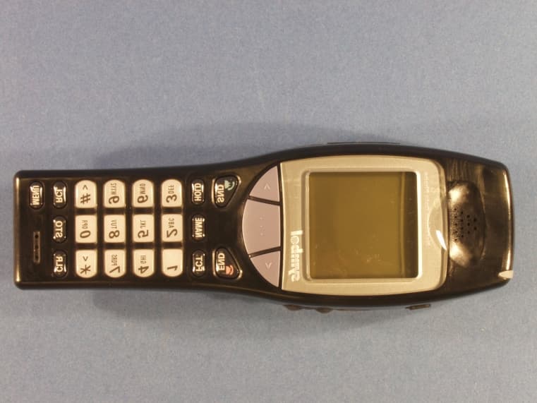
Click to zoom
Application Details
- Equipment Class
- DSS - Part 15 Spread Spectrum Transmitter
- Date of Grant
- Sep 03, 2001
- Application Purpose
- Original Equipment
- Date of Application
- Jun 04, 2001
- Frequency Range
- 2412.00000000 - 2462.00000000
- Company
- Symbol Technologies Inc
- Country
- United States
Documents & Files
Document Text
Text extracted from the exhibit documents filed with the FCC. Open a document above to read the original.
Users Manual
NetVision ® Data Phone User Guide www.symbol.com Copyright © 1999 by Symbol Technologies, Inc. All rights reserved. Symbol, Spectrum24 and NetVision are registered trade- marks of Symbol Technologies, Inc. Symbol Technologies, Inc. One Symbol Plaza Holtsville, N.Y. 11742-1300 Telephone:(800)SCAN234 (516)738-2400, TLX:6711519 A Spectrum24 ® Wireless LAN Solution 70-20620-01 Call Indicator Volume Buttons Adjusts the current call volume. Mini-Headset Jack For hands-free use. Menu Scrolling Keys END Key Refuses or ends a call. Powers offthe phone. Returns to a previous menu. Ends data collection. Previous/Next Keys Tabs between application fields. FCT Key Accesses additional Data Phone features. Mouthpiece Use the Menu Scrolling Keysto select phone menu items and to set volume and contrast levels. CLR Key Removes the last digit entered from the keypad. Do no into sc High Gain Antenna. The antenna does not extend. Laser Scanner Scan Key Activates the scanner for data collection. Serial Port Connector For network administration use. Data Phone Display Displays phone status, menu options, messages and application prompts. Earpiece SND Key Powers onthe phone. Accepts or activates a call. Sends data. Selects menu items. NAME Key Displays names from the call list. MENU Key Displays the phone user menu. RCL Key Recalls the last number dialed, and accesses the speed-dial directory. STO Key Stores a number in the speed-dial directory. HOLD Key Places a call on hold. NetVision ® Data Phone Feature Overview ot stare scanner! Battery Attaching/Detaching 1.Attach the battery to the phone by aligning the feet on the battery with the notches on the phone. Push the battery top into the phone until the latch clicks. 2. Detach the battery by depressing the latch and pulling the battery top away from the phone. Battery Swapping NetVision Data Phone users can swap the battery during data operations when the phone is idle. The Data Phone beeps to warn that the battery has reached a level that can- not support phone functions. Remove the battery without first powering off the phone and install a fully charged battery. Install a fresh battery within three minutes to retain user configuration. After installing the new battery, press SNDto connect and log into the network. Technical Data Battery: 7.2 volts rechargeable; Lithium ion Battery Life: 150 minutes (2.5 hours) talk time, 24 hours standby operation per charge. Frequency Range: 2.4 - 2.485 GHz Wireless Output Power: 100 mW Light Source: Visible Laser Diode at 650 nm Laser Class: CDRH Class II, IEC 825 Class 2 Drop Specification: 3.3 ft./1 meter to tile Temperature: -30°C to 60°C/-22°F to 140°F To prevent injury or burns, do not short-circuit the bat- tery terminals with metal objects. Use only approved batteries and charging accessories with the NetVision Data Phone. Do not charge the battery in a charger other than a Symbol NetVision Data Phone Charger. Battery Charging The NetVision Data Phone Battery Charger can recharge two batteries, attached to and detached from the Data Phone. When charging the battery attached to the phone, turn off the phone before inserting it into the charger. Place the battery into the rear charger slot or battery and phone combina- tion into the front charger slot. The indicators for each slot on the charger indicate the following status: GREENbattery is fully charged and ready for use. REDbattery is charging; wait until the status indicator changes to GREEN before using battery. Fully charge the battery before using the NetVision Data Phone. AMBERcharger is charging the other battery. The charger begins the charging cycle for the first device inserted; the charging cycle for the other device begins after the first cycle finishes. Operating the Phone Press SNDto power on the Data Phone and activate a network connection. After the initial message, the phone displays Idle status. Connecting to the Network The quality of Data Phone communication and data collection depends on the network radio recep- tion. Large objects and other radiating devices can affect network reception. Use the Radio Signal Strength Indicator on the display to monitor reception quality. The NetVision Data Phone can also cause radio-frequency interference to other devices. Use the Data Phone only in areas designated by the network administrator. If the phone cannot connect to the network, the phone displays No Network . The phone cannot make or receive calls, receive paged messages or perform data collection when disconnected from the network. The NetVision Data Phone ships with basic defaults for immediate use. The network administrator preloads each Data Phone with configuration data to enable the advanced features and access other system-related applications. The network administrator configures NetVision Data Phones in one of two ways: - As a shared phone, the system administrator preloads the Data Phone with a list of user profiles. This allows you to pick up and use any Data Phone. - As a personal phone, the system administrator preloads the Data Phone for one user. The Setup user profile is reserved for the network administrator. Support and Symbol user profiles are reserved for Symbol Technologies support personnel. Logging on to a NetVision Data Phone Users log onto the network to operate the NetVision Data Phone. Obtain a user name and password (PIN) from the network administrator. 1. Press FCT, NAMEto log on to the network. 2. Select the user name from the list. 3. Press SNDto select the user name. 4. Enter the PIN for the user name and press SNDto complete the network log in. Battery status icon User name Network and phone status Radio Signal Strength Indicator (RSSI) Phone line and APPS icon Receiving Calls with the NetVision Data Phone The NetVision Data Phone provides user-configurable features to determine how a call is answered. The caller ID feature allows you to identify callers before answering the call. You can select from three answering …
Text truncated - open the document above for the full version.
Attestation Statements
Manufacturer’s Certification Declaration of Conformity Standard to which conformity is declared: FCC Part 15 Subpart B Class B Manufacturer/Importer’s Information Name: Symbol Technologies, Inc. Address: 6480 Via Del Oro San Jose, CA 95119-1208 Telephone Number: 408-528-2600 Equipment Information Type of Equipment: 2.4 GHz Spread Spectrum Transceiver Trade Name: Spectrum 24 NetVision Data Phone Model Number: DP4026 Test Report Reference: J20029320 I, the undersigned, herby declare that the equipment specified above conforms to Part 15 of the FCC Rules. (Signature) Norman H. Nelson, Sr. EMC Engineer (Name & Title) November 30, 2000 (Date)
Cover Letter(s)
Network Systems Organization Norman H. Nelson Symbol Technologies, Inc. 6480 Via Del Oro Federal Communications Commission San Jose, CA 95119-1208 Equipment Approval Services Voice: (408) 528-2649 P.O. Box 358315 FAX: (408) 528-2740 Pittsburgh, PA 15251-5315 [email protected] Re: Certification request for the Symbol model DP4046 Spectrum 24® DS Data Phone Date: June 16, 2001 To The Commission: This certification request is for the Spectrum 24 model DP4046 Spectrum 24® DS Data Phone. The DP4046 is a wireless phone and integrated bar code scanner utilizing the model DM4046 2.4 GHz direct sequence IEEE 802.11 compliant transceiver. The DM4046 radio is the radio in the previously certified model NP4046. This request is for approval of a Part 15 transmitting device operating under 15.247(c) and its associated antennas for this phone type device. Symbol Technologies, Inc. manufactures information systems that are employed in commercial establishment to assist in controlling inventory. Spectrum 24 is a Wireless Local Area Network (WLAN) used along with hand held computers to assist in information collection typically in retail stores, warehouses, and factories. The following files are electronically submitted as attachments. Exhibit Type File Name Confidential Block Diagram ------------------------------------DP4046 BlkDia.pdf X Cover Letters: -------------------------------------DP4046 Cover Letter.pdf Attestation Statements ---------------------------DP4046 DOC.pdf External Pictures ----------------------------------DP4046 Ext Pics.pdf Internal Pictures -----------------------------------DP4046 Int Pics.pdf ID Label/Location Info --------------------------DP4046 Label.pdf Operational Description -------------------------DP4046 OpDesc.pdf X Test Report-----------------------------------------DP4046 ProcGain.pdf RF Exposure ---------------------------------------DP4046 RF Exposure.pdf RF Exposure ---------------------------------------DP4046 SAR Rpt.pdf RF Exposure ---------------------------------------DP4046 SAR PlotPrim.pdf RF Exposure ---------------------------------------DP4046 SAR PlotAux.pdf Schematics -----------------------------------------DP4046 Schem.pdf X Test Report Photos -------------------------------DP4046 Test Pix.pdf Test Report-----------------------------------------DP4046 Tst Rpt.pdf User Manual ---------------------------------------DP4046 User Man.pdf Note that the RF Exposure exhibit contains all of the antenna information. There are 2 internal antennas included in this submission. Symbol Technologies, Inc. ("Symbol"), requests that the Block Diagram, Schematics, and Operational Description Exhibits of the above referenced application be withheld from routine availability for public inspection pursuant to Section 0.459 of the Commissions Rules and Freedom of Information Act ("FOIA") Exemption 4, 5 U.S.C. 552(b)(4). DP4046 Cover Letter.doc Page 2 of 2 These exhibits consist of "trade secrets [or] commercial or financial information obtained from a person and privileged or confidential", 5 U.S.C. 552(b)(4), and is therefore entitled to protection from disclosure under FOIA. The documents in question contain trade secrets: detailed technical descriptions, specifications and schematics for a product to be offered for sale. These materials provide particulars on the product design that can be ascertained from inspection of the product itself only with extraordinary expenditures of time and effort, if at all. This information would give Symbol's would-be competitors an unearned and unwarranted competitive advantage. Moreover, the documents contain "commercial information" within the scope of FOIA Exemption 4. This information is the product of Symbol's investment of money, personnel, and other resources. The result of that investment is a fairly earned position in the marketplace. Premature release of the information threatens substantial and unwarranted harm to Symbol's competitive position. For these reasons, Symbol has taken pains to keep this technical information confidential, and intends to continue doing so. Symbol customarily withholds this information from persons outside the employ of Symbol and certain of its suppliers and contractors, and even within these groups routinely limits access to persons having a particular need for the information. If the Commission were to make these documents public, it would be giving away hard won fruits of Symbol's labors without compensation. The filing fee required for this request was paid by credit card electronically. If there are any questions about this request, please call me at the number above. Thank you for your attention. Respectfully submitted, Norman H. Nelson
Cover Letter(s)
FccID:H9PDP4046DS Data Phone Conf Num: EA101239 Original Equip. Corespondence # 20085 Date Emailed: 7/27/01 1 Question Testing above 1 GHz was done at 300 kHz. A 1MHz RBW is required. Answer: Only those harmonics above 19 GHz were tested with a RBW of 300 KHz. To lower the test setup noise floor for those frequencies, the distance was reduced from 3 to 1m and the RBW decreased to 300 KHz. Still the emmissions were below the noise floor. All other freq > 1000 MHz were tested at the proscribed RBW. 2 Question The device has 1 main antenna and 2 auxiliary antennas. Do any of the antennas transmit simultaneously with any of the other antennas? Answer: There is one main antenna and one aux antenna and they can not transmit simultaneously. 3 Question Provide external photo's of the belt clip to clearly identify it. Answer: Please see the attached photo. 4 Question Only 1 set of SAR auxiliary antennas were submitted. There are two auxiliary antennas. Answer: There is only one aux antenna. 5 Question Ensure that the SAR values in the plots agree with those listed in the table of SAR results. Answer: The Aux antenna SAR plots were labeled 1- 15 instead of 16-30. I have uploaded the corrected plots. Page 1 of 1 Tuesday, August 14, 2001 06:16 PM
ID Label/Location Info
bar codeabc here MOD: <Model Number> SN: <Device Serial No.> MANUFACTURED: <Date> SEE USER GUIDE FOR PATENT INFORMATION This device complies with Part 15 of the FCC Rules and RSS-210 of Industry Canada. Operation is subject to the following two conditions: (1) this device my not cause harmful interference, and (2) this device must accept any interference received, including interference that may cause undesired operation. This Class B digital apparatus complies with Canadian ICES-003. Cet appareil numØrique de la classe B est comforme la norme NMB-003 du Canada. IEEE ADDRESS REF NO <MAC Address Number> FCC ID : H9PDP4046 CANADA ID : <Canadian Certification No.> NetVision® Phone Symbol Technologies, Inc. Holtsville, N.Y. MADE IN JAPAN LISTED ACCESSORY I.T.E. 9B97 C0168R N410 Proposed Device Label
RF Exposure Info
Network Systems Organization RF Exposure Antenna Summary FCC ID: H9PDP4046 EA101239 Original Equip. DS Data Phone Output Power: 145 Remote DC Factor: 0.108 mW AP DC Factor: 1.000 Source Based Portable Antennas (R < 5cm) Ant No Model Symbol P/N Gain (dBi) Cable Loss (dB) Pout (dBm) EIRP (mW) TR Status Device Use Type 01. Phone PCB 50-21900-045 2.0 0.18 21.43 23.7 Tested + SAR Di p ole Hand Set 02. Phone Stickon 50-21900-044 2.0 0.22 21.40 23.5 Tested + SAR Di p ole Hand Set Antenna Gain listed without cableTR Status refers to wither the antenna was tested. If not refer to the directed antenna test data Page 1 of 1 Saturday, June 16, 2001 12:51 PM Duty Cycle Factors are applied to MPE and EIRP Mobile & Wireless Systems Phone PCB Rev 1 Phone PCB Ant enna The Phone PCB antenna is 2 dBi omni- directional in azimuth plane. It is mounted internally as shown in the attached photo. The Phone PCB uses a Hirose FL series connector. In use it is 1.5 cm from a users head. It is used in mobile devices. Antenna Photo Location Phone Handset Pattern Omni Type Dipole Max Gain 2 dBi Physical 1.5” x 0.3” Cable CO-6F-DSB- CX501X32AWG Symbol P/N 50-21900-045 Mobile & Wireless Systems Phone PCB Rev 1 Antenna installed in DP4046 Voice communication device DP4046 Use Photo Mobile & Wireless Systems Phone Stick On Rev 1 Phone Stick On Antenna The Phone Stick On antenna is 2 dBi omni-directional in azimuth plane. It is mounted internally as shown in the attached photo. The Phone Stick On uses a Hirose FL series connector. In use it is 3.4 cm from the users head. It is used in mobile devices. Antenna Photo Location Phone Handset Pattern Omni Type Dipole Max Gain 2 dBi Physical 2.12” x 0.2” Cable CO-6F-DSB- CX501X32AWG Symbol P/N 50-21900-044 Mobile & Wireless Systems Phone Stick On Rev 1 Antenna installed in DP4046 Voice communication device DP4046 Use Photo Network Systems Organization Norm Nelson, Sr. EMC Engineer Page 1 of 2 11/22/00 Duty Cycle Calculations The maximum duty cycle of a 802.11 compliant transmitter is dependent on the data rate and the processing speed of the device the transmitter is installed in. The duty cycle is the ratio of the maximum transmitter on time divided by the total cycle time which is composed of the maximum on time and the minimum off time. The maximum on time is dependent on the data rate. The 802.11 spec mandates what the maximum data payload for a packet may be. The data pay load along with packet addressing and other network overhead information determine the maximum size of a packet. The maximum transmitter on time is the longest time that it will take the radio to transmit the packet. In the case of Symbol’s Spectrum 24 products the 1 Mbps data rate is the slowest. For the cycle time the minimum off time consists of an acknowledgement from the receiver, the shortest carrier sense time and the shortest packet construction time. The acknowledgment and carrier sense times are driven by the 802.11 protocol while the packet construction time is driven by the processing power of the radio host. For access points , laptops, and workstations with fast processors the construction time is fairly short. While for hand held battery powered terminals with slower processors the construction time can be really significant. Directly related to the duty cycle is data throughput of a link. The lower the duty cycle the lower the data throughput. Longest On Time N = Maximum # of data bytes / packet OP = Overhead bytes/packet Ton = ((N + OP) * 8 bits/byte) / 10^6 bits/sec = 4.872 mS Maximum Duty Cycle Factor DCF = Ton / (Ton + Toff) Shortest Off Time CST = Carrier Sense Time APA = AP Ack time PCT = Packet Construction Time Toff = CST + APA + PCT Radios LA2400 CR-1 1Mbps FH LA3020 Duo 2Mbps FH LA3021 Proj C 2Mbps FH LA4111 T1 11Mbps DS LA4121 T2 11Mbps DS XX3010 FH Phone 1Mbps FH DM4026 DS Phone 11Mbps DS Duty Cycle Variables Radio N OP CST (uS) APA (uS) PCT (uS) AP Rmt AP Rmt AP Rmt AP Rmt AP Rmt LA2400 548 548 61 61 100 100 220 220 3000 10000 LA3020 548 548 61 61 100 100 220 220 2000 2000 LA3021 548 548 61 61 100 100 220 220 2280 2370 LA4111 548 548 61 61 100 100 220 220 1640 1660 LA4121 548 548 61 61 100 100 220 220 1600 1690 NP3010 N/A 32 N/A 80 N/A 100 N/A 220 N/A 7119 DP3010 N/A 32 N/A 80 N/A 100 N/A 220 N/A 7119 DM4026 N/A 32 N/A 80 N/A 100 N/A 220 N/A 7119 Duty Cycle Calculations Norm Nelson, Sr. EMC Engineer Page 2 of 2 11/22/00 Duty Cycle Factors Radio Data Rate AP Remote LA2400 1 Mbps 60% / -4.4 dB 32 % / -9.9 dB LA3020 1 Mbps 68% / -3.4 dB 68% / -3.4 dB LA3021 1 Mbps 65% / -3.7 dB 64% / -3.9 dB LA4111 1 Mbps 71.3% / -2.9 dB 71.1% / -3.0dB LA4121 1 Mbps 71.8% / -2.9 dB 70.8% / -3.0dB NP3010 1 Mbps N/A 10.75% / -19.4 dB DP3010 1 Mbps N/A 10.75% / -19.4 dB DM4026 1 Mbps N/A 10.75% / -19.4 dB Regulatory Addenum: FCC RF EXPOSURE GUIDELINES To comply with RF safety requirements use the specific belt clip. All other belt clips should be avoided and may not comply with RF safety requirements. The preceding statement is presently being added to the QRG (Quick Reference Guide –User’s Manual) for the Symbol DS Phone line. This addition will be covering the model NP4046 and DP4046 NetVision ® phones. Norm Nelson Symbol Technologies Inc 6480 Via Del Oro Drive San Jose, CA 95119-1208 Phone: (408) 528-2649 Fax: (408) 528-2740 E-mail: [email protected]
RF Exposure Info
A 1365 Adams Court, Menlo Park, CA 94025 Symbol Technologies, Inc., Model No: DP-4046 Date of Test: March 20 & 26, 2001 Report # 2036369F11FCC Part 2 SAR Evaluation Table of Contents 1.0 JOB DESCRIPTION.................................................................................................. 2 1.1 Client Information................................................................................................. 2 1.2 Equipment under test (EUT).................................................................................. 2 1.3 Test plan reference................................................................................................. 2 1.4 System test configuration....................................................................................... 3 1.4.1 System block diagram & Support equipment........................................ 3 1.4.2 Test Position for Brain.......................................................................... 4 1.4.3 Test Position for Muscle....................................................................... 4 1.4.4 Test Condition...................................................................................... 5 1.5 Modifications required for compliance................................................................... 6 1.6 Additions, deviations and exclusions from standards............................................. 6 2.0 SAR EVALUATION.................................................................................................. 7 2.1 SAR Limits............................................................................................................ 7 2.2 Configuration Photographs.................................................................................... 8 2.3 System Verification............................................................................................. 16 2.4 Evaluation Procedures......................................................................................... 16 2.5 Test Results ......................................................................................................... 17 3.0 EQUIPMENT........................................................................................................... 21 3.1 Equipment List .................................................................................................... 21 3.2 Tissue Simulating Liquid..................................................................................... 22 3.3 E-Field Probe Calibration.................................................................................... 24 3.4 Measurement Uncertainty.................................................................................... 25 3.5 Measurement Traceability.................................................................................... 25 4.0 WARNING LABEL INFORMATION - USA......................................................... 26 5.0 REFERENCES......................................................................................................... 27 6.0 Document History..................................................................................................... 28 APPENDIX A - SAR Evaluation Data................................................................................ 29 APPENDIX B - E-Field Probe Calibration Data................................................................ 30 APPENDIX C – Antenna Specifications............................................................................. 31 A 1365 Adams Court, Menlo Park, CA 94025 Symbol Technologies, Inc., Model No: DP-4046 Date of Test: March 20 & 26, 2001 Report # 2036369F12FCC Part 2 SAR Evaluation 1.0 JOB DESCRIPTION 1.1 Client Information The EUT has been tested at the request of: Company:Symbol Technologies, Inc.. Address:6480 Via Del Oro San Jose, CA 95119-1208 USA Name of contact:Mr. Norm Nelson Telephone: (408) 528-2649 Fax:(408) 528-2740 1.2 Equipment under test (EUT) Product Descriptions: Equipment NETVISION 2.4 GHZ DIRECT SEQUENCE SPREAD SPECTRUM RADIO. Unit is available with a main antenna and an auxiliary antenna. Trade NameSymbol Technologies, Inc. Model No:DP-4046 FCC ID H9PDP4046 S/N No.Not Labeled Category Portable RF ExposureUncontrolled Environment Frequency Band (up link) 2402-2480 MHzSystemDSSS EUT Antenna Descriptions Main Antenna Type Name: Phone PCB Sanyo #: IRA4L90A15401 Symbol #: 50-21900-045 Gain: 2 dBi Auxiliary Antenna Type Name: Phone Stick On Sanyo #: IRA4L90A15401 Symbol #: 50-21900-044 Gain: 2 dBi Location:Main Antenna: Internal Auxiliary Antenna: Internal Note: For details on antennas see Appendix C Use of Product :Wireless Voice/Data communications Manufacturer:Symbol Technologies, Inc. Production is planned[X ] Yes, [ ] No EUT receive date:March 19, 2001 EUT received condition:Prototype in good condition. Test start date:March 20, 2001 Test end date:March 26, 2001 1.3 Test plan reference A 1365 Adams Court, Menlo Park, CA 94025 Symbol Technologies, Inc., Model No: DP-4046 Date of Test: March 20 & 26, 2001 Report # 2036369F13FCC Part 2 SAR Evaluation FCC rule part 2.1093, FCC Docket 96-326 & Supplement C to OET Bulletin 65 1.4 System test configuration 1.4.1 System block diagram & Support equipment The EUT was tested without the need for support equipment. EUT A 1365 Adams Court, Menlo Park, CA 94025 Symbol Technologies, Inc., Model No: DP-4046 Date of Test: March 20 & 26, 2001 Report # 2036369F14FCC Part 2 SAR Evaluation 1.4.2 Test Position for Brain The DP-4046 was configured for testing in a typical fashion (as a customer would normally use it), and in the confines as outlined in C95.1 (1992) and Supplement C of OET 65 (1998). The DP-4046 was placed in the intended use position, i.e. CENELEC 80 o position. This position is defined by a reference plane and a line. The reference plane of the head is given by three points, the auditory canal opening of both ears and center of the closed mouth. The reference line of the DP-4046 is…
Text truncated - open the document above for the full version.
Test Report
LA-4121 Processing Gain Calculations Page 1 of 1 Processing Gain Calculation Symbol Technologies LA-4121 WLAN PC Card Norman H. Nelson, Sr. EMC Engineer May 8, 2000 Symbol calculated the processing gain from the jamming margin of the LA-4121 transceiver as specified in 15.247 (e)(2). Test Setup The purpose of the jamming test is to determine how effective the modulation, coding and decoding is at rejecting the corrupting influence of a CW jammer signal. Where as most setups us a BER to generate data and count errors because the modulator chip architecture prevents injecting data after chipping, Symbol chose to use another LA- 4121 as the transmitter and data generator. A link between the transmitter and receiver is made and path loss adjusted so that the BER is 10E-5. The path loss is then reduced by 10 dB so that the BER approaches zero. Finally a jamming signal is combined with the transmitted signal to degrade the system performance. The jamming signal amplitude is then adjusted to the point that the BER is degraded to 10E-5. The relationship between PER and BER is as follows. In order to get a good packet we need 8 x 1024 good bits. Stated mathematically. 1-PER = (1-BER) (8*24) . Or BER=1-(1- PER) (1/(8*1024)) . Jamming Margin Test Setup ATE Controller Mini Tower PC Signal Generator GPIB Power Meter GPIB GPIB GPIB Step Attn (50 dB) RS-232 RX Card Laptop (PER Receiver) TX Card Laptop (PER Generator) Fixed Attn (20 dB) RS-232 The major blocks of the jamming margin test are a transmitter, a receiver, and a jammer. The TX card formats and transmits packets of data consisting of 1024 bytes LA-4121 Processing Gain Calculations Page 2 of 2 each. The RX card then attempts to read each packet. The Signal Generator provides the jamming signal. The splitters combine the TX and jammer signals and provide a port to measure the power levels within the RF link. The PER Generator Laptop controls the transmit card and the PER receiver laptop controls the receiver. The ATE PC automates the test by controlling the two laptops, the Signal Generator, and the power meter. Software blocks The key to this test is three software programs Packet Generator (PG), Packet Counter (PC), and Jam Margin Controller (JMC). The first to work together to form the PER measurement system and the last to control the jammer, the power meter, and the other two software blocks. Packet Generator runs on the PG Laptop and controls the transmit card. A trigger on the serial port line commands the TX card to generate and transmit 1000 packets of 1024 bytes at a specified data rate. Packet Counter runs on the PER receiver laptop and queries the RX card for the number of packets it has received. A trigger on the serial port causes the Packet Counter to report the number of packets to the ATE Controller and reset the Packet Counter to zero. The Packet counter automatically detects the data rate of the incoming packet stream. The other Jamming Margin Controller (JMC) runs on the ATE PC and controls the Signal Generator, the Power Meter, and PGAC running on the Dual Slot laptop. PG commands the TX card to transmit a set of 1000 packets of 1024 bytes of data. The RX card receives the packets and PC sends the number of good packets received to the serial port. The functional purpose is the same as a BER meter. A new set is run every time a new trigger is received on the serial port from JMC. JMC controls the jammer, the power meter, and the Dual Slot program. JMC sets the frequency and level of the signal generator that acts as a jammer. JMC then sends a trigger to PG. The trigger causes PG to run another set of packets and PC reports the number of good packets back to JMC. The packet error rate is then converted to BER and JMC adjusts the Jammer level appropriately. A search algorithm is built into JMC to have the jammer converge to the right level for a 10E-5 BER. The jammer resolution is .1 dB. When the jammer level causes a BER of 10E-5, the JMC program turns off the TX card and commands the power meter to read the jammer power level. JMC then turns off the jammer, turns on the TX card, and measures its power. Then S is offset for duty cycle and J/S is calculated from the two power measurements and recorded to disk. In this way as the test progresses and the TX card warms up power fluctuations due to temperature are referenced out. The test is then repeated at the next jammer frequency. In this instance the test is conducted across the band of a single channel at 50KHz steps. LA-4121 Processing Gain Calculations Page 3 of 3 Data Rate and Modulation Description 11 Bit Barker Word 22 MHz 11 MBps CCK 5.5 MBps CCK 802.11 DSSS QPSK 2MBps Barker QPSK 802.11 DSSS BPSK 1 MBps Barker BPSK 11 chips 1 MSps 1 bit used to BPSK code word 11 chips 1 MSps 2 bits used to QPSK code word 8 chips 1.375 MSps 2 bits encoded to 4 complex code words; 2-QPSK 8 chips 1.375 MSps I, Q I, Q I, Q Modulation Technique and Data rates I, Q 6 bits encoded to 64 complex code words; 2-QPSK ceee eee ee jj j j jj jj = −− +++++ ++ + +++ + {,,, ,,,,} ()() () () ()() () φφφφφφφ φφφ φφ φφ φφφ φφφ 123413412 4 14 12313 121 Code set Mode Chip/Symbol 1 MBps 11/1 2 MBps 11/2 5.5 MBps 8/2 11 MBps 8/8 Gp Calculation from J/S d…
Text truncated - open the document above for the full version.
Contact Information
Applicant
Qianlin Zhou(Regulatory Specialist)
Technical Contact
Symbol Technologies, Inc.Norman H Nelson
[email protected]408-528-2649
6480 Via Del Oro · San Jose, California · United States
Test Firm
Intertek Testing Services NA Inc.John Quigley
Technical Specifications
| # | Rule Parts | Frequency Range | Power Output | Tolerance |
|---|---|---|---|---|
| 1 | 15C | 2.41 GHz - 2.46 GHz | 145.00 mW | ppm |
Other Applications from Symbol Technologies Inc

H9PCCHUB1
Jun 30, 2015Customer Concierge
Equipment Class
NII - Unlicensed National Information Infrastructure TX
H9PAP7562
May 10, 2015802.11 abgn/ac Access Point
Equipment Class
DTS - Digital Transmission System
H9PTC75AH
Mar 26, 2015Touch Computer
Equipment Class
NII - Unlicensed National Information Infrastructure TX
H9PRA1202
Sep 24, 2014UHF Narrowband Radio Module
Equipment Class
TNB - Licensed Non-Broadcast Station Transmitter
H9PEMG101
Aug 26, 2014802.15.4 Gateway
Equipment Class
DTS - Digital Transmission System