H9PLA3021-500WLAN PC Card
Symbol Technologies Inc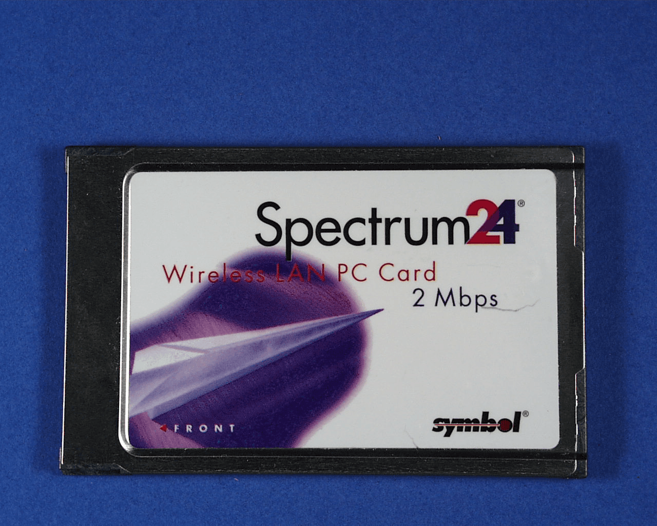
Click to zoom
Application Details
- Equipment Class
- DSS - Part 15 Spread Spectrum Transmitter
- Date of Grant
- Mar 13, 2000
- Application Purpose
- Original Equipment
- Date of Application
- Jul 15, 1999
- Equipment Note
- WLAN PC Card
- Frequency Range
- 2402.00000000 - 2480.00000000
- Company
- Symbol Technologies Inc
- Country
- United States
Documents & Files
Document Text
Text extracted from the exhibit documents filed with the FCC. Open a document above to read the original.
Users Manual
Spectrum24 Wireless LAN Adapter Models 3020 PC Card & 3025 ISA Adapter Product Reference Guide 70-20505-01 October 1998 iiSpectrum24 Wireless LAN Adapter User Guide Copyright Copyright © 1998 by Symbol Technologies, Inc. All rights reserved. No part of this publication may be modified or adapted in any way, for any purposes without permission in writing from Symbol. The material in this manual is subject to change without notice. Symbol reserves the right to make changes to any product to improve reliability, function, or design. No license is granted, either expressly or by implication, estoppel, or otherwise under any Symbol Technologies, Inc., intellectual property rights. An implied license only exists for equipment, circuits, and subsystems contained in Symbol products. Symbol, the Symbol logo and Spectrum24 are registered trademarks of Symbol Technologies, Inc. Other product names mentioned in this manual may be trademarks or registered trademarks of their respective companies and are hereby acknowledged. Novell and LAN Workplace are registered trademarks of Novell Inc. Patents This product is covered by one or more of the following U.S. and foreign Patents: U.S. Patent No.4,360,798; 4,369,361; 4,387,297; 4,460,120; 4,496,831; 4,593,186; 4,603,262; 4,607,156; 4,652,750; 4,673,805; 4,736,095; 4,758,717; 4,816,660; 4,845,350; 4,896,026; 4,897,532; 4,923,281; 4,933,538; 4,992,717; 5,015,833; 5,017,765; 5,021,641; 5,029,183; 5,047,617; 5,103,461; 5,113,445; 5,130,520 5,140,144; 5,142,550; 5,149,950; 5,157,687; 5,168,148; 5,168,149; 5,180,904; 5,229,591; 5,230,088; 5,235,167; 5,243,655; 5,247,162; 5,250,791; 5,250,792; 5,262,627; 5,262,628; 5,266,787; 5,278,398; 5,280,162; 5,280,163; 5,280,164; 5,280,498; 5,304,786; 5,304,788; 5,306,900; 5,321,246; 5,324,924; 5,337,361; 5,367,151; 5,373,148; 5,378,882; 5,396,053; 5,396,055; 5,399,846; 5,408,081; 5,410,139; 5,410,140; 5,412,198; 5,418,812; 5,420,411; 5,436,440; 5,444,231; 5,449,891; 5,449,893; 5,468,949; 5,471,042; 5,478,998; 5,479,000; 5,479,002; 5,479,441; 5,504,322; 5,519,577; 5,528,621; 5,532,469; 5,543,610; 5,545,889; 5,552,592; 5,578,810; 5,581,070; 5,589,679; 5,589,680; 5,608,202; 5,612,531; 5,619,028; 5,664,229; 5,668,803; 5,675,139; 5,693,929; 5,698,835; 5,705,800; 5,714,746; 5,723,851; 5,734,152; 5,734,153; 5,745,794; 5,754,587; 5,658,383; D305,885; D341,584; D344,501; D359,483; D362,453; D362,435; D363,700; D363,918; D370,478; D383,124; D391,250. Invention No. 55,358; 62,539; 69,060; 69,187 (Taiwan); No. 1,601,796; 1,907,875; 1,955,269 (Japan). European Patent 367,299; 414,281; 367,300; 367,298; UK 2,072,832; France 81/03938; Italy 1,138,713. Symbol Technologies, Inc. One Symbol Plaza Holtsville, N.Y. 11742-1300 Telephone:(800)SCAN234/(516)738-2 Spectrum24 Wireless LAN Adapter User Guideiii Regulatory Addendum Congratulations on your purchase of this Symbol Technologies product. It is manufactured to the highest standards to ensure trouble-free operation and durability. In order to comply with various U.S. and International regulatory requirements, we have included this addendum with your product. It is an all-encompassing document that applies to the complete line of Symbol products. Therefore, many of the labels shown, and statements indigenous to other devices may not apply to your particular product. Radio Frequency Interference Requirements This device has been tested and found to comply with the limits for a Class A digital device pursuant to Part 15 of the Federal Communications Commissions Rules and Regulation. These limits are designed to provide reasonable protection against harmful interference when the equipment is operated in a commercial environment. This equipment generates, uses, and can radiate radio frequency energy and, if not installed and used in accordance with the instruction manual, may cause harmful interference to radio communications. Operation of this equipment in a residential area is likely to cause harmful interference in which case the user will be required to correct the interference at his own expense. However, there is no guarantee that interference will not occur in a particular installation. If the equipment does cause harmful interference to radio or television reception, which can be determined by turning the equipment off and on, the user is encouraged to try to correct the interference by one or more of the following measures: •Re-orient or relocate the receiving antenna. •Increase the separation between the equipment and receiver. •Connect the equipment into an outlet on a circuit different from that which the receiver is connected. •Consult the dealer or an experienced radio/TV technician for help. Radio Frequency Interference Requirements - Canada This Class A digital apparatus meets the requirements of the Canadian Interference-Causing Equipment Regulations. CE Marking and European Union Compliance Products intended for sale within the European Union are marked with the CEMark which indicates compliance to applicable Directives and European Normes (EN), as follows. Amendments to these Directives or ENs are included: Normes (EN), as follows. Applicable Directives: •Electromagnetic Compatibility Directive 89/336/EEC •Low Voltage Directive 73/23/EEC Applicable Standards: •EN 55 022 - Limits and Methods of Measurement of Radio Interference Characteristics of Information technology Equipment •EN 50 082-1 - Electromagnetic Compatibility - Generic Immunity Standard, Part 1: Residential, commercial, Light Industry ivSpectrum24 Wireless LAN Adapter User Guide •IEC 801.2 - Electromagnetic Compatibility for Industrial Process Measurement and Control Equipment Part 2: Electrostatic Discharge Requirements •IEC 801.3 - Electromagnetic Compatibility for Industrial Process Measurement and Control Equipment Part 3: Radiated Electromagnetic Field Requirements •IEC 801.4 - Electromagnetic Compatibility for Industrial Process Measurement and Control Equipment Part 4: Electrical Fast Transients Requirem…
Text truncated - open the document above for the full version.
Cover Letter(s)
Mobile and Wireless Systems Division Norman H. Nelson Symbol Technologies, Inc. Federal Communications Commission2145 Hamilton Ave Equipment Approval ServicesSan Jose, CA 95125-5905 P.O. Box 358315Voice:(408)369-2649 Pittsburgh, PA 15251-5315FAX: (408) 369-2740 [email protected] Re: Certification Request for FCC ID: H9PLA3021-500 Date: July 16, 1999 To The Commission: This certification request is for the Spectrum 24 model LA3021-500 PCMCIA WLAN Module. The LA3021 series of WLAN modules are an improved version of the current LA2400 and LA3020 modules. The LA3021 series operates in the same manner as the LA3020. Symbol Technologies, Inc. manufactures information systems that are employed in commercial establishments to assist in controlling inventory. Spectrum 24 is a Wireless Local Area Network (WLAN) used along with hand held computers to assist in information collection typically in retail stores, warehouses, and factories. The following files are electronically submitted as attachments. Exhibit TypeFile NameConfidential Block DiagramLA3021 BlkDia.pdfX Cover Letter:LA3021-500 CvrLet.pdf External PicturesLA3021-500 ExtPics.pdf ID Label/Location InfoLA3021-500 Label.pdf Internal PhotosLA3021-500 IntPics.pdf Operational DescriptionLA3021 OpDesc.pdfX SchematicsLA3021 Schem.pdfX Test ReportLA3021-500 TstRpt.pdf Test Report AddenumLA3021-500 TstRptA.pdf Users ManualLA3021 UsrMan.pdf Note that in the test report (tstrpt.pdf) those tests marked “Test Not Performed” are located in the Test Report Addenum (TstRptA.pdf). Symbol Technologies, Inc. ("Symbol"), requests that the Block Diagram, Schamatics, and Operational Description Exhibits of the above referenced application be withheld from routine availability for public inspection pursuant to Section 0.459 of the Commissions Rules and Freedom of Information Act ("FOIA") Exemption 4, 5 U.S.C. 552(b)(4). These exhibits consist of "trade secrets [or] commercial or financial information obtained from a person and privileged or confidential", 5 U.S.C. 552(b)(4), and is therefore entitled to protection from disclosure under FOIA. The documents in question contain trade secrets: detailed technical descriptions, specifications and schematics for a product to be offered for sale. These materials provide particulars on the product design that can be ascertained from inspection of the product itself only with extraordinary expenditures of time and effort, if at all. This information would give Symbol's would-be competitors an unearned and unwarranted competitive advantage. Moreover, the documents contain "commercial information" within the scope of FOIA Exemption 4. This information is the product of Symbol's investment of money, personnel, and other resources. The result of that investment is a fairly earned position in the marketplace. Premature release of the information threatens substantial and unwarranted harm to Symbol's competitive position. For these reasons, Symbol has taken pains to keep this technical information confidential, and intends to continue doing so. Symbol customarily withholds this information from persons outside the employ of Symbol and certain of its suppliers and contractors, and even within these groups routinely limits access to persons having a particular need for the information. If the Commission were to make these documents public, it would be giving away hard won fruits of Symbol's labors without compensation. The filing fee required for this request is submitted by credit card account as entered on Form 159 mailed under separate cover. If there are any questions about this request, please call me at the number above. The filing fee required for this request is submitted by credit card account as entered on Form 159 mailed under separate cover. If there are any questions about this request, please call me at the number above. Thank you for your attention. Respectfully submitted, Norman H. Nelson
Cover Letter(s)
Network Systems Organization Norman H. Nelson Symbol Technologies, Inc. 6480 Via Del Oro San Jose, CA 95119-1208 Voice:(408) 528-2649 FAX: (408) 528-2740 [email protected] Federal Communications Commission Equipment Approval Services P.O. Box 358315 Pittsburgh, PA 15251-5315 Re: FCC ID H9PLA3021-500 Ref # 9578 Date: October 13, 99 Dear Reviewer, In response to the following Email: On Thu, 9 Sep 1999 17:07:45 -0400, [email protected] (OET) wrote: >To:Norman Nelson, Symbol Technologies, Inc. >From:Joe Dichoso >[email protected] >FCC Application Processing Branch > >Re:FCC ID H9PLA3021-500 >Applicant:Symbol Technologies Inc >Correspondence Reference Number:9578 >731 Confirmation Number:EA94853 >Date of Original E-Mail:09/09/1999 > > >1) File a composite Certification application for the peripheral portion. If the peripheral portion >will be DOC approved, provide the DOC Certificate and a revised label with DOC requirements. I have emailed a request to Bette Taube to change the 731 13(a) to yes, 13(c) to filed at same time, and FCC ID to H9PLA3021-500. I have also uploaded the DOC to the FCC web site, and mailed in another 159 form with the EBC fees. Because of the size of the unit the required label information is included in the User Manual as permitted by 15.19(b)(3). > >2) The MMCX antenna connector is not unique. A search on the internet shows that it is >available to anyone. Therefore, it is not in compliance with Section 15.203. Please >correct/explain accordingly. > This connector is not available through retail distributors and requires special tools, knowledge, and assembly techniques that are not available to the general public. This connector has been approved for our H9PLA3020 radio (see correspondence # 3413) as well as many of our competitor’s products. All of our antennas either have the MMCX connector and cable assembly permanently attached to the antenna (internal antennas) or the antenna is terminated in a reverse polarity BNC that requires a special adapter cable that is RP-BNC to MMCX (see attached drawing). >3) The receiver input bandwidth must match the transmitter bandwidth. What is the receiver input >bandwidth? The receiver input bandwidth is 1 MHz. > >4) Provide a list of all of the antennas. Indicate the output power, antenna type with model >number and the antenna gain. As stated in #2 above, all cables are permanently affixed to the antennas with either a reverse polarity BNC or a MMCX connector on the free end. In general the antennas that are internal to hand held devices are MMCX and the portable antennas are RP-BNC. The list of antennas is attached. > >5) The requested output power is 250 mW. The technical descriptions indicate that the output >power is designed for 500 mW. The sample tested shows a maximum output power of 331 mW. >The device will only be granted with the maximum output power shown on the tests 331 mW. >If you want 500 mW, you need to test a sample that operates at this output power. Please >address this discrepancy. Please grant the maximum output power for this device 331 mW. 500 mW was a goal set by marketing and due to conflicting requirements was reduced. > >6) The RF safety calculations were done with 250 mW. The device was tested at 331 mW and >was designed for 500 mW. These calculations must be redone at the maximum output power. >A review of the RF safety exhibits will be performed once the output power issue is resolved. The attached antenna list includes the RF safety calculations. Symbol based these calculations by rounding up 331 mW to 350 mW. I hope these answers are satisfactory. Respectfully, Norman H. Nelson Antenna Summary Table Non Hand Held Antennas Ant # Model Type Gain 1 Usage MPE Distance 2 Symbol P/N Mfgr. Mfgr. P/N 1 Plane Antenna Plane 0 dBi Ceiling, Laptop 5.3 cm ML-2499-PSA1-00 2a Dipole Antenna (4’ Cable 3 ), Dipole Array 3 dBi Ceiling 7.4 cm ML-2499-HPA1-00 (4 ft) 2b Dipole Antenna (15” cable) Dipole Array 0 dBi Ceiling 5.3 cm ML-2499-HPA2-00 (15 ft) 3 Rubber Duck Dipole 1 dBi Ceiling, Computer 5.9 cm ML-2499-APA1-00 4 Yagi Yagi 9 dB Mast/Wall 14.8 cm ML-2499-YGA1-01 5 Patch Patch 4 dBi Wall/Rooftop 8.3 cm ML-2499-PTA1-01 6 Panel Patch 7dBi Wall/Rooftop 11.8 cm ML-2499-PNA1-01 7 End Cap F-Element 0 dBi Laptop Card Slot 5.3 cm ML-3099-PCEC-01 15 Parabolic Grid Parabolic 9.5 dBi Mast 15.7 cm ML-2499-PGA1-00 16 S2406 Dipole Array 2 dBi Ceiling 6.6 cm ML-2499-WHA1-20/30 18 Corner Patch Patch 5 dBi Wall, ceiling 9.3 cm ML-2499DLA1-06 19 Ceiling Mount Panel Plane 3.6 dBi Ceiling 8.0 cm ML-2499-SD24-06 21 Mag Mount Dipole -3 dBi Vehicle 6.6 cm ML-2499-MGA1-01 1 Antenna gain includes permanently attached cable loss. 2 MPE Distance is based on Symbol’s worst case H9PLA3021-500 assuming 350 mW of transmitter power. 3 All cables are permanently attached to the antenna with a reverse polarity BNC on the other end. A short MMCX to RP-BNC cable is required for mating to PC Card. Hand Held Antennas Ant # Model Type Gain 4 Usage MPE Distance 5 Symbol P/N Mfgr. Mfgr. P/N 8 4140 Whip < 0 dBi hand held 5.3 cm DR10-2 9 4640 Patch < 0 dBi hand held 5.3 cm 21-17486-02 10 2140 F-Element < 0 dBi hand held 5.3 cm 10-17577-01 11 6140 F-Element < 0 dBi hand held 5.3 cm 10-35305-01 12 6840 F-Element < 0 dBi hand held 5.3 cm 10-32290-01 13 1040 F-Element < 0 dBi Worn on Arm SAR 10-32447-01 14 Huber Suhner Dipole 1.8 dBi Hand Held 5.3 cm Huber Suhner 9090.16.0001 17 Criticare F-Element 0 dBi hand held 5.3 cm Tecom 703443 20 2040 F-Element < 0 dBi hand held 5.3 cm 10-17577-02 4 Antenna gain includes permanently attached cable loss 5 MPE Distance is based on Symbol’s worst case 350 mW H9PLA3021-500 for all antennas
Cover Letter(s)
Network Systems Organization Norman H. Nelson Symbol Technologies, Inc. Federal Communications Commission6480 Via Del Oro Equipment Approval ServicesSan Jose, CA 95119-1208 P.O. Box 358315Voice:(408) 528-2649 Pittsburgh, PA 15251-5315FAX: (408) 528-2740 [email protected] Re: FCC ID H9PLA3021-500 Ref # 10270 Date: October 26, 99 Dear Reviewer, In response to the following Email: >To:Norman Nelson, Symbol Technologies, Inc. >From:Joe Dichoso >[email protected] >FCC Application Processing Branch > >Re:FCC ID H9PLA3021-500 >Applicant:Symbol Technologies Inc >Correspondence Reference Number:10270 >731 Confirmation Number:EA94853 >Date of Original E-Mail:10/20/1999 > >1) With regard to the DOC label requirements, Section 15.19(b)3 requires the Trade name, model number >and FCC logo to be displayed on the device. To make room on your device the statement required by >Section 15.19(a)3 may be placed in the manual. Supply a corrected label with the DOC requirements an >also has the Certification requirements(FCC identifier). A corrected label has been uploaded to the FCC web site. >2) With regard to the MMCX connector, you state that this connector requires special tools, knowledge >and assembly techniques. Please clarify in detail. What special tools, knowledge and assembly techniques >are REQUIRED to be used for this connector? Please see the attached assembly instructions from the manufacturer. >3) FYI, The RF Safety exhibits are under review and will be forwarded as soon as possible. Respectfully, Norman H. Nelson Assembly instructionSeries MMCXT3NO. 9077 Tools and materials required: Soldering iron 80 to 100 Watts/220 to 240°C Solder Sn/Pb 60/40, 0,8 mm 0, activated rosin flux Alcohol, brush, blade (74 Z-O-O-68) SR cable stripping toolNo. W 157 Soldering fixtureNo. W 58 lnsertsNo. W 59/W 60/ W 133 Locator toolNo. W 61 Assembly tool74 2-o-o-225 -.___ This connector is supplied in 3 parts Suitable cables e. g. Centre contact: capt. Braid: Connectors for copper jacket cable Cable entry: soldered Connector types: (e. g.) 16 MMCX 50-I-4 EZ 47 (.047") soldered soldered II A - 8% B Y ~-- I I Cut cable end perpendicular to cable axis. Cut back copper jacket using cable stripping tool W 157. See instruction sheet No. 9144 for detailed description. The tool must be set for L= ‘2,5mm stripping dimension. Prepare cable according to diagram. Remove dielectric using a blade. Slide ferule A over the cable and seat firmly angainst cable jacket. Slide connector housing B over cable and fix cable in fixture. Tighten locator tool W 61 fully against housing B. Solder connector housing B to cable, avoid excessive heat, Immediately cool down clean with alcohol. V Jmax.zooN @a-- I I Solder inner conductor to contact. Place cover C on rear opening of body B. Press cover C into housing B with assembly tool. SUHNER’S skilled staff and specialised equipment are available to carry out complete R. F. lead-assembly on your behalf. We mount your connectors on cab/es at economic prices! Please contact our representative for further details of this service. @ HUBER+SUHNER LTD. CH-9100 HERISAU
Cover Letter(s)
Network Systems Organization Norman H. Nelson Symbol Technologies, Inc. 6480 Via Del Oro San Jose, CA 95119-1208 Voice:(408) 528-2649 FAX: (408) 528-2740 [email protected] Federal Communications Commission Equipment Approval Services P.O. Box 358315 Pittsburgh, PA 15251-5315 Re: FCC ID H9PLA3021-500 Ref # 9798 Date: November 24, 1999 Dear Reviewer, In response to the following Email: On Fri, 24 Sep 1999 10:10:02 -0400, [email protected] (OET) wrote: To:Norman Nelson, Symbol Technologies, Inc. From:Joe Dichoso [email protected] FCC Application Processing Branch Re:FCC ID H9PLA3021-500 Applicant:Symbol Technologies Inc Correspondence Reference Number:9798 731 Confirmation Number:EA94853 Date of Original E-Mail:09/24/1999 Please address the following RF safety issues. When downloading information with respect to this e-mail, submit any exhibits in the RF exposure folder. Contact Kwok Chan at [email protected] if you have any questions. This is a 250 mW DSS PC card from Symbol Technology, EA 94853 - 1. The 731 form (or EAS) is indicating 250 mW . Measured output in section 4.1 of EMC report has 24.5- 25.2 dBm (281-331 mW). This same section also describes EUT tested at 20.3 dBm (107 mW). The users manual is describing this transmitter as a 100 or 500 mW transmitter. The appropriate output for this transmitter needs clarification. The output power determined here may affect how other items (in the following) should be addressed. The output power for the EAS should be 330 mW. The 20.3 dBm is a misprint that was carried over from the test report of the 100 mW version of this transmitter. The correct power in the test report is 24.9 dBm. The power level of the middle channel. 2. The manual describes a PC Cards and an ISA cards for this transmitter, typically for laptop and regular PC computer configurations. The MPE info describes a number of handheld products from Symbol Technology and third parties. Do handheld products use the PC Card or ISA card, or if there is a modular version of this transmitter for OEM integration into handheld and other products? All hand held products for Symbol and third parties use the PC Card version of the transmitter. The ISA card is used in desktop and tower style PC systems and uses mobile antennas. The PC Card is inserted into a PCMCIA socket of the ISA card. Note: most of the following items have been explained to the applicant in similar filing (EA 91115) approved previously for 250 mW. Currently there is a pending Class II Change filing (EA 94292) which has similar output discrepancy problems (250 mW vs 500 mW). There is also a 100 mW version of this transmitter filed under EA 94885, pending, that has the same RF exposure issues as this one. 3. The MPE info included in the filing describes a total of 21 antennas, among them, 8 are typically mounted at remote locations. These remote antennas can generally satisfy MPE requirements by providing users and installers with appropriate installation and operating instructions - with respect to 2.1091 of FCC rules, a minimum of 20 cm is needed. Please clarify by what means will the responsible parties be informed regarding installation and operating requirements for satisfying MPE limits for these 8 remote antennas. For all mobile transmitters that are greater than 100 mW Symbol includes the following safety statement that is published in the installation instructions for the device. Symbol Safety Statement : “The maximum permissible exposure (MPE) limit for these antennas when used with a Spectrum24 device is 6.5 inches (16 cm). The MPE limit is calculated to reflect the distance a person should maintain from the antenna. The MPE distance does not apply to transient exposure due to incidental passage closer than the MPE limit.” 4. For the other 13 antennas, 7 are intended for incorporating into handheld products (6 Symbol Technology products and 1 third party), 1 for a body-worn product from Symbol and the other 5 are typically for standalone use with laptop and regular computers. These 13 antenna and product configurations are required to satisfy SAR requirements for portable transmitters since they operate within 20 cm of persons. Spread Spectrum transmitters (DSS) are generally categorically excluded from routine RF exposure evaluation for demonstrating compliance, however, 15.247(b)(4) specifically require DSS to operate in a manner that ensures the public is not exposed to RF levels exceeding FCC requirements. In order to determine SAR compliance with respect to 15.247(b)(4), information relating to the construction, packaging, antenna location, operating conditions and configurations of each individual handheld product and standalone antenna are needed to estimate an individual product configuration's potential for exceed ing SAR limit and to determine if separate SAR evaluation must be requested to demonstrate or determine compliance. Please clarify accordingly for these 13 antennas so that we can determine compliance based on the exposure conditions established by the individual device or product and its output power level. Note: For portable transmitters, RF exposure is highly dependently on near-field coupling conditions; therefore, product packaging and operating configurations are important factors. In certain situations, identical antennas or ones with substantially lower gain could produce higher SAR due to poor antenna matching, high case/ground currents or enhanced RF coupling in specific product configurations. For these reasons, we cannot extend the SAR results for the WWC-1040 to other handheld products. It is acceptable to use SAR results for the WWC-1049 to support the WWC-1040 since the only difference is in memory configurations, provided the SAR results are not very close to the limit. Symbol uploaded a revised test report addendum that includes specifics of antenna location, use, product packaging, and operating configurations. 5. Based on the operating conditions and configurations of th…
Text truncated - open the document above for the full version.
ID Label/Location Info
A Intertek Testing Services NA Inc. 1365 Adams Court, Menlo Park, CA 94025 USA Telephone 650-463-2900 Fax 650-463-2910 http://www.worldlab.com i Symbol Technologies Emissions Testing Performed on the 2.4 GHz 500mW Radio Model: LA3021-500-US FCC Part 15 Subpart B Class B (DoC) Date of Test: May 13 - June 9, 1999 Job#: J99013298 Report#: J99013298c Date of Report: June 23, 1999 Total No. of Pages Contained in this Report: 18 + Data Pages This report shall not be reproduced except in full, without written approval of Intertek Testing Services. This report must not be used to claim product endorsement by NVLAP or any agency of the U.S. Government. The results contained in this report were derived from measurements performed on the identified test samples. Any implied performance of other samples on this report is dependent on the representative of the samples tested. A Symbol TechnologiesDate of Test: May 13 - June 9, 1999 Report # J99013298c FCC Part 15 Class B DoC iii Table of Contents 1.0 Introduction ........................................................................................................................................ 1 2.0 Description of Equipment .............................................................................................................. 1 3.0 Test Summary ..................................................................................................................................... 1 4.0 System Test Configuration ............................................................................................................. 2 4.1Support Equipment................................................................................................................ 2 4.2Block Diagram of Test Setup................................................................................................ 3 4.3Justification .............................................................................................................................. 4 4.4Software Exercise Program...................................................................................................4 4.5Mode of Operation During Test .......................................................................................... 4 4.6Modifications Required for Compliance ............................................................................. 4 4.7Additions, deviations and exclusions from standards ....................................................... 4 5.0 Radiated Emissions .......................................................................................................................... 5 5.1Radiated Emission Limits...................................................................................................... 5 5.2Field Strength Calculation ..................................................................................................... 6 5.3Configuration Photographs - Radiated Emissions ............................................................ 7 5.4Test Data.................................................................................................................................. 8 6.0 AC Mains Line-Conducted Emissions ....................................................................................... 9 6.1Line Conducted Emission Limits......................................................................................... 9 6.2Configuration Photographs.................................................................................................10 6.3Test Data................................................................................................................................11 7.0 Test Equipment ...............................................................................................................................12 7.1Equipment List .....................................................................................................................12 7.2Measurement Uncertainty ...................................................................................................13 7.2.1Radiated Emission - 3m Open Site Test Distance.............................................13 7.2.2Conducted Emission - AC Supply .......................................................................13 7.3Measurement Traceability ...................................................................................................13 8.0 Miscellaneous Information or Other Comments ...................................................................14 8.1Labeling - USA......................................................................................................................15 8.2Labeling - Canada .................................................................................................................16 8.3Compliance Information - USA .........................................................................................17 8.4Manufacturer's Certification................................................................................................18 A Symbol TechnologiesDate of Test: May 13 - June 9, 1999 Report # J99013298c FCC Part 15 Class B DoC 1 of 18 1.0 Introduction This report is designed to show compliance with the FCC Part 15, …
Text truncated - open the document above for the full version.
Contact Information
Applicant
Qianlin Zhou(Regulatory Specialist)
Technical Contact
Symbol Technologies, Inc.Norman H Nelson
[email protected]408-369-2649
2145 Hamilton Ave. · San Jose, California · United States
Non-Technical Contact
Symbol Technologies, Inc.Laraine Regnani
[email protected]408-369-2650
Test Firm
Intertek Testing Services NA Inc.John Quigley
Technical Specifications
| # | Rule Parts | Frequency Range | Power Output | Tolerance |
|---|---|---|---|---|
| 1 | 15C | 2.40 GHz - 2.48 GHz | 331.00 mW | ppm |
Other Applications from Symbol Technologies Inc

H9PCCHUB1
Jun 30, 2015Customer Concierge
Equipment Class
NII - Unlicensed National Information Infrastructure TX
H9PAP7562
May 10, 2015802.11 abgn/ac Access Point
Equipment Class
DTS - Digital Transmission System
H9PTC75AH
Mar 26, 2015Touch Computer
Equipment Class
NII - Unlicensed National Information Infrastructure TX
H9PRA1202
Sep 24, 2014UHF Narrowband Radio Module
Equipment Class
TNB - Licensed Non-Broadcast Station Transmitter
H9PEMG101
Aug 26, 2014802.15.4 Gateway
Equipment Class
DTS - Digital Transmission System