H9PLA4131MWLAN PC Card
Symbol Technologies Inc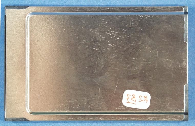
Click to zoom
Application Details
- Equipment Class
- DSS - Part 15 Spread Spectrum Transmitter
- Date of Grant
- Jul 24, 2001
- Application Purpose
- Original Equipment
- Date of Application
- Jul 24, 2001
- Equipment Note
- WLAN PC Card
- Frequency Range
- 2412.00000000 - 2462.00000000
- Company
- Symbol Technologies Inc
- Country
- United States
Documents & Files
Document Text
Text extracted from the exhibit documents filed with the FCC. Open a document above to read the original.
Users Manual
Copyright Copyright © 2001 by Symbol Technologies, Inc. All rights reserved. No part of this publication may be modified or adapted in any way, for any purposes without permission in writing from Symbol Technologies, Inc. (Symbol). The material in this manual is subject to change without notice. Symbol reserves the right to make changes to any product to improve reliability, function, or design. No license is granted, either expressly or by implication, estoppel, or otherwise under any Symbol Technologies, Inc., intellectual property rights. An implied license only exists for equipment, circuits and subsystems contained in Symbol products. Symbol, the Symbol logo and Spectrum24 are registered trademarks of Symbol Technologies, Inc. Other product names mentioned in this manual may be trademarks or registered trademarks of their respective companies and are hereby acknowledged IBM is a registered trademark of International Business Machine Corporation. Microsoft, Windows, and Windows NT are registered trademarks of Microsoft Corporation. Novell and LAN Workplace are registered trademarks of Novell Inc. Toshiba is a trademark of Toshiba Corporation. Patents This product is covered by one or more of the following U.S. and foreign Patents:U.S. Patent No. 4,460,120; 4,496,831; 4,593,186; 4,603,262; 4,607,156; 4,652,750; 4,673,805; 4,736,095; 4,758,717; 4,816,660; 4,845,350; 4,896,026; 4,897,532; 4,923,281; 4,933,538; 4,992,717; 5,015,833; 5,017,765; 5,021,641; 5,029,183; 5,047,617; 5,103,461; 5,113,445; 5,130,520; 5,140,144; 5,142,550; 5,149,950; 5,157,687; 5,168,148; 5,168,149; 5,180,904; 5,216,232; 5,229,591; 5,230,088; 5,235,167; 5,243,655; 5,247,162; 5,250,791; 5,250,792; 5,260,553; 5,262,627; 5,262,628; 5,266,787; 5,278,398; 5,280,162; 5,280,163; 5,280,164; 5,280,498; 5,304,786; 5,304,788; 5,306,900; 5,321,246; 5,324,924; 5,337,361; 5,367,151; 5,373,148; 5,378,882; 5,396,053; 5,396,055; 5,399,846; 5,408,081; 5,410,139; 5,410,140; 5,412,198; 5,418,812; 5,420,411; 5,436,440; 5,444,231; 5,449,891; 5,449,893; 5,468,949; 5,471,042; 5,478,998; 5,479,000; 5,479,002; 5,479,441; 5,504,322; 5,519,577; 5,528,621; 5,532,469; 5,543,610; 5,545,889; 5,552,592; 5,557,093; 5,578,810; 5,581,070; 5,589,679; 5,589,680; 5,608,202; 5,612,531; 5,619,028; 5,627,359; 5,637,852; 5,664,229; 5,668,803; 5,675,139; 5,693,929; 5,698,835; 5,705,800; 5,714,746; 5,723,851; 5,734,152; 5,734,153; 5,742,043; 5,745,794; 5,754,587; 5,762,516; 5,763,863; 5,767,500; 5,789,728; 5,789,731; 5,808,287; 5,811,785; 5,811,787; 5,815,811; 5,821,519; 5,821,520; 5,823,812; 5,828,050; 5,850,078; 5,861,615; 5,874,720; 5,875,415; 5,900,617; 5,902,989; 5,907,146; 5,912,450; 5,914,478; 5,917,173; 5,920,059; 5,923,025; 5,929,420; 5,945,658; 5,945,659; 5,946,194; 5,959,285; 6,002,918; 6,021,947; 6,047,892; 6,050,491; 6,053,413; 6,056,200; 6,065,678; 6,067,297; 6,068,190; 6,082,621; 6,084,528; 6,088,482; 6,092,725; 6,101,483; 6,102,293; 6,104,620; 6,114,712; 6,115,678; 6,119,944; 6,123,265; 6,131,814; 6,138,180; 6,142,379; D305,885; D341,584; D344,501; D359,483; D362,453; D363,700; D363,918; D370,478; D383,124; D391,250; D405,077; D406,581; D414,171; D414,172; D418,500; D419,548; D423,468; D424,035; D430,158; D430,159; D431,562 Invention No. 55,358; 62,539; 69,060; 69,187 (Taiwan); No. 1,601,796; 1,907,875; 1,955,269 (Japan); European Patent 367,299; 414,281; 367,300; 367,298; UK 2,072,832; France 81/03938; Italy 1,138,713 Symbol Technologies, Inc. One Symbol Place Holtsville, NY. 11742-1300 *70-20745-02* 70-20745-02 Revision D www.symbol.com Quick Reference Guide Wireless LAN Adapter LA-4100 Series PC Card Declaration of Conformity We, Symbol Technologies, Inc., of One Symbol Plaza, Holtsville, NY 11742-1300, USA decalare under our sole responsibility that the product Spectrum24HR, LA4131, 11Mbps type II Radio Card Spectrum24HR, LA4121, 11Mbps Type II Radio Card Spectrum24HR, LA4111,11Mpbs Type II Radio Card to which this product relates, is in conformity with the following standards and/or other normative documents: EN 300 328-2 v1.1.1 (2000-07) Radio: 2.4GHz Spread Spectrum EN 301 489-1 v1.2.1 (7-2000) Part 1: EMC, Common technical requirement EN 301 489-17 v1.1.1 (9-2000) Part 17: Specific conditions for wide-band data and Hiperlan equipment EN 60950: 1992 Uncl. 1-4, 11: Safety of Information Technology Equipment. We hereby declare that all essential radio test have been carried out and that the above named product is in conformity to all the essential requirements of Directive 1999/5/EC. The conformity assessment procedure referred to in Article 10(5) and detailed in Annex IV of Directive 1999/5/EC has been followed with the involvement of the following Notified Body(ies): BABT, Claremont House, 34 Molesey Road, Walton-on-Thames, KT12 4RQ. Identification mark: 0168 The equipment also carries the Class 2 equipment identifier. The technical documentation relevant to the above equipment can be made available for inspection on appplication to: Symbol Technologies EMEA, Symbol Place, Winnersh Triangle, Berkshire, RG 41 5TP, UK Customer Support Symbol Techmologies is committed to providing its customers with world-class customer service and technical support. The Symbol Support Center operates as the single point of contact for any technical probelm, question or support issue. The Support Center ooperates all year, 24 hours a day, staffed by full-time professional Technical Specialists. If Symbol cannot solve the problem immediately within its tiered, technical-support center, access to all technical disciplines within Symbol become available for further assistance and support. First response/contact within 24 hours or one business day. Response by email, fax, or telephone. North America Contacts Inside North America, contact Symbol at: Symbol Technologies, Inc. One Symbol Plaza, Holtsville, New York 11742-1300 Telephone: 1-516-738-2400/1-800-SCAN 234; Fax 1-516-738-5990 Symbol Support Center: Telephone: 1-800-653-5350; Fax: (516) 563-5410; Emai…
Text truncated - open the document above for the full version.
Cover Letter(s)
FccID:H9PLA4131MWLAN PC Card, 11 Mbps, T3 Conf Num: Original Equip. Corespondence # 72301 Date Emailed: 7/23/01 1 Question Please provide User Manual. Answer: User manual is attachted. 2 Question Please provide Processing Gain measurement data. Answer: Processing Gain Report is attached. 3 Question Please provide request for confidentiality letter. Answer: Confidentiality request cover letter is attached. 4 Question In the Page 3 of test report, the frequency range for this device is listed from 2412 - 2462 MHz with 11 channels. However, in the page 9 of opeational description, there are total of 13 channels listed with frequency range from 2412 - 2472 MHz. Please explain. Answer: The upper two channels are used in Japan. For the US they are excluded. That is why they are listed in the operational description but not in the test report which tests to the US spec. Firmware locks out channels 12 and 13 for the US configuration of the radio. 5 Question As indicated in the test setup photos, EUT was tested with extended cable out from the Notebook computer to the EUT. Please explain the rational behind this type of setup. Answer: According to the FCC, ANSI C63.4-1992 Fig 9(c ) shows 10 cm between pieces of equipment. The FCC wanted us to follow this guidline and use a non-shielded cable extender. This would simulate a worst case situation when the EUT was integrated in access points instead of just with a laptop. 6 Question RF antenna conducted test: Page 23 of test report shows the emission peak is detected on 2411.69MHz. It is beyond the frequency band of 2412 - 2462 MHz. Please explain. Answer: The carrier is modulated with a long sequence of random data. Because peak hold is used on the spectrum analyzer and the nature of radom data the peak may not occure at the carrier frequency. In this case the peak falls just lower than the carrier freq of 2412 MHz ±50ppm. Page 1 of 2 Tuesday, July 24, 2001 01:08 PM Corespondence # 72301 Date Emailed: 7/23/01 7 Question RF antenna conducted test, Page 33 of test report shows the emission peak is detected on 2462.54MHz. It is beyond the frequency band of 2412 - 2462 MHz. Please explain. Answer: The carrier is modulated with a long sequence of random data. Because peak hold is used on the spectrum analyzer and the nature of radom data the peak may not occure at the carrier frequency. In this case the peak falls just higher than the carrier freq of 2462 MHz ±50ppm. 8 Question Is this application requested for modulor approval ? This device is a type II PCMCIA card with external antenna connectors. The typical antenna installations as described in RF Exposure document which show the access point be installed with antenna but not the PCMCIA card. Operational description indicates that PCMCIA card is intended for Notebook, handheld or fixed computers to provide wireless access ( Page 8 ). Please explain how the various proposed antennas to be used with such mobile applications. Answer: The operational description includes all configurations even those not included in this application. The Notebook config is covered under a separate application for portable devices. This application is for mobile configurations for fixed computers or access points. For these mobile configurations the antennas are mounted as indicated in the RF Exposure document. 9 Question The max. proposed antenna gain is 11.4dbi. Please address 15.247 (b)(3) and 15.247(b)(3)(I ) de facto EIRP requirements. Answer: Since the sourced based average power of the transmitter is 60 mW x .72 = 43.2 mW or 16.3 dBm this is reduced 13.7 dB below the allowed max power of 30 dBm. So for point to multi-point applications we can have a max antenna gain of 6 + 13.7 or 19.7 dBi. For point to point we can have a max antenna gain of 6 + 3(13.7) or 47.1 dBi. The 11.4 dBi proposed antenna is well below these limits. 10 Question Please provide MPE calculation to show how the RF separation distances were calculated. Answer: For ant #1 see the attached file MPE calc.pdf Page 2 of 2 Tuesday, July 24, 2001 01:08 PM
Cover Letter(s)
FccID:H9PLA4131MWLAN PC Card, 11 Mbps, T3 Conf Num: Original Equip. Corespondence # 72501 Date Emailed: 7/25/01 1 Question Page 7 of test report mentioned antenna gain of 12.5dBi. In accordance to the antenna specification in RF exposure exhibit, there is no such antenna with 12.5dBi gain. Please explain. Answer: The 12.5 dBi is a typo. It should be 11.4 dBi, the antenna with the highest gain. The original Panel 9 was tested with only 1.5 ft of cable which gave it the 12.5 dBi of net gain. We corrected the cable length which dropped the gain to 9 dBi. The 11.4 dBi yagi as the highest gain antenna was used to test for EIRP. The new EIRP value was updated but the antenna gain wasn't. Page 1 of 1 Wednesday, July 25, 2001 08:12 PM
Cover Letter(s)
TCB RF Exposure Review Procedure Statement FCC ID:H9PLA4131M Transmitter Category Device Type Product Category Approval and Review Procedures Used Specific Procedures: VI Wireless LAN PC Card Part 15 Mobile Transmitters Section F SP(1), SP(3),SP(5), SP(7), SP(8), SP(9) Grant Conditions – Output is peak conducted. This device has five antenna configurations, as described in the filing. All five antennas can only be used for fixed configurations. The antenna(s) used for this transmitter must be installed to provide a separation distance of at least 20 cm from all persons and must not beco-located or operating in conjunction with any other antenna or transmitter. This device must transmit with asource-based time-averaging duty factor not exceeding 71.8%. End-users and installers must be provided withantenna installation instructions and transmitter operating conditions for satisfying RF exposure compliance. SP1 Output power measured with Power meter :17.8dBm@high channel. Five antennas withmax. antenna gain of 11.4 ( net gain) . Antennas are to be used in fixed configuration..Antenna cables are specified in the antenna installation procedures. This device is intendedto be installed in Access point or in fixed computer. This device is not intended forportable configuration. Duty cycle of 71.8% is considered in using various antennas. SP3 RF exposure compliance statement can be found in User Manual The RF exposurelanguages stated in this document comply with the requirement. SP5 Total 11 channels . Frequency Range : 2402 – 2462 MHz.. Firmware locks out channel 12and 13 for the US configuration. . SP7 Antenna installation procedures has been provided in the RF exposure exhibit SP8 User Manual has provided adequate instruction on how to connect the device. SP9 TCB has reviewed the Grant conditions and has determined the Grant conditions areapplicable to the device. Reviewed by Mike KuoCompliance Certification ServicesJuly 25, 2001
ID Label/Location Info
PROD FAM: TRILOGY 3 SYMBOL DESCRIPTION: LBL:LCD,LA-4131-WW CTRY CODE: WW COUNTRY: US.CANADA,JAPAN AND EU. SEE 21-40866-XX FOR EU COUNTRY LIST SN POOL: STANDARD LBL STOCK PN: 63-38047-02 SEE NOTE 2 LBL SCRIPT : 51489013 *SEE NOTE 1 SEE NOTE 6 SEE NOTE 5 ADD VARIABLE FIELD FOR PLANT CODE P/N: LA-4131-XXX....-WW S/N: XXXXXXXXXXXXXXX SYMBOL TECHNOLOGIES INC., HOLTSVILLE N.Y. BAR CODE FCC ID: H9PLA4131M CANADA : XXXXXXXX N410 FREQ: MAX 2400-2483.5 MHz 0168 MAX 100 mW THIS CLASS B DIGITAL APPARATUS COMPLIES WITH CANADA ICES-003. CET APPAREIL NUMERIQUE DE LA CLASSE B EST CONFORME A LA NORME NMB-003 DU CANADA. TYPE: WPC2011BWW RLAN AFFIX COUNTRY STAMP HERE MADE IN XXX.... XXXX.... 2.4DS4 R NYDA0XXX/ GZDA0XXX LA-4131 NOTES: UNLESS OTHERWISE SPECIFIED 1. SCRIPT FILE TO BE CREATED BY SAN JOSE, AND TRANSFERRED TO MANUFACTURING. SEE ELTRON SPEC P/N SP-10083-01. SCRIPT FILE MUST MATCH THIS DOCUMENT EXACTLY. PCX FILES AVAILABLE FOR REGULATORY PORTION. SEE BELOW. * 2. LABEL STOCK P/N IS SUBJECT TO CHANGE. CHECK BOM FOR ACTUAL PART NUMBER. 3. IN ALL CASES "XXX......" REPRESENTS VARIABLE FIELDS IN SCRIPT FILE. ACTUAL NUMBER OF CHARACTERS IN SCRIPT FILE MAY VARY. 4. IN THE CASE OF MULTIPLE APPROVALS THE ID NUMBER AND TYPE NUMBERS APPEAR IN SAME ORDER. 5. PART NUMBER MAY OR MAY NOT HAVE DASH BEFORE COUNTRY CODE. SEE BOM FOR ACTUAL MODEL DESCRIPTION. 6. COUNTRY OF ORIGIN REQUIRED. 69-51489-01.3 69-51489-01.3.PCX PPD: 66325
RF Exposure Info
Network Systems Organization RF Exposure Antenna Summary FCC ID: H9PLA4131M Original Equip. WLAN PC Card, 11 Mbps, T3 Output Power: 60 Remote DC Factor: 0.710 mW AP DC Factor: 0.720 Source Based Mobile Antennas (R>2m) Ant No Model Symbol P/N Gain (dBi) Cable Loss (dB) Pout (dBm) MPE (cm) TR Status Device Use Type Net Gain 01. Ceiling Panel 50-21900-015 3.3 1.50 2.3 Tested Plane Fixed 16.28 1.8 02. Panel 7.5 ML-2499-PNA1-01 11.0 3.48 4.4 Tested Panel Fixed 14.30 7.5 03. Panel 9 50-21900-047 13.0 3.53 5.5 Tested Patch Fixed 14.26 9.5 04. Pipe Bomb 11"x4' 50-11901-048P 5.2 1.00 3.0 Tested Di p ole Arra y Fixed 16.78 4.2 05. Yagi ML-2499-YGA1-00 13.9 2.50 6.9 Tested Ya g i Fixed 15.28 11.4 Antenna Gain listed without cableTR Status refers to wither the antenna was tested. If not refer to the directed antenna test data Page 1 of 1 Thursday, July 05, 2001 01:51 PM Duty Cycle Factors are applied to MPE and EIRP Mobile & Wireless Systems Ceiling Panel Rev 1 Ceiling Panel Antenna The Ceiling Panel antenna is 1.8 dBi omni- directional in azimuth plane The Plane uses a reverse polarity BNC connector. It is mounted on a horizontal surface. In its use it would be mounted on a ceiling farther than 20 cm from a persons body. It is used with mobile devices. The following RF exposure information is included in a prominent place in the device’s user manual to inform the user of safety issues as required by OET Bulletin 65, Supplement C when ever the device configuration could reduce the MPE distance to be less than 20 cm. “Important Note: To comply with FCC RF exposure requirements, no one may remain within 20 cm of the antenna for extended periods of time.” Antenna Photograph Location Horizontal Surface Pattern Omni Type Plane Max Gain 1.8 dBi Physical See attached dwg Cable 6 ft (Plenum-rated) Symbol P/N ML-2499-SD24-00 MPE Distance See summary table Mobile & Wireless Systems Ceiling Panel Rev 1 Ceiling Configuration Mobile & Wireless Systems Panel Rev 1 Panel Antenna The Panel is a 7.5 dBi antenna with a 44° beamwidth in azimuth plane The Panel uses a reverse polarity BNC connector. It is mounted on a vertical surface. In its use it would be mounted on a wall near a ceiling farther than 20 cm from a persons body. It is used with mobile devices. The following RF exposure information is included in a prominent place in the device’s user manual to inform the user of safety issues as required by OET Bulletin 65, Supplement C when ever the device configuration could reduce the MPE distance to be less than 20 cm. “Important Note: To comply with FCC RF exposure requirements, no one may remain within 20 cm of the antenna for an extended period of time.” Antenna Photograph Location Vertical Surface Pattern Directional Type Panel Max Gain 7.5 dBi Physical See attached dwg Cable 20 ft (Plenum-rated) Symbol P/N ML-2499-PNA1-01 MPE Distance See summary table Mobile & Wireless Systems Panel 9 Rev 1 Panel 9 Antenna The Panel 9 antenna is 9 dBi directional in azimuth plane The Plane uses a reverse polarity BNC connector. It is mounted on a horizontal surface. In its use it would be mounted on a wall or mast farther than 20 cm from a persons body. It is used with mobile devices. The following RF exposure information is included in a prominent place in the device’s user manual to inform the user of safety issues as required by OET Bulletin 65, Supplement C. Antenna Photograph “CAUTION: Exposure to Radio Frequency radiation. To comply with FCC RF exposure requirements this antenna shall be installed to ensure a minimum separation distance of 20 cm from all persons during normal operating conditions.” Location Wall, Mast Pattern Directional Type Panel Gain 9.5 dBi Physical See attached dwg Cable 430cm RG-58 Symbol P/N 50-21900-047 MPE Distance See summary table Mobile & Wireless Systems Panel 9 Rev 1 Typical Antenna Installation Scheme Mobile & Wireless Systems Pipe Bomb 11” Rev 1 Pipe Bomb 11”Antenna The Pipe Bomb 11”antenna is 4.2 dBi omni- directional in azimuth plane The Pipe Bomb 11” uses a reverse polarity BNC connector. It is mounted on the ceiling or on a wall near the ceiling. In its use it would be farther than 20 cm from a persons body. It is used with mobile devices. It is available with either a 4’ or 15’ cable. The following RF exposure information is included in a prominent place in the device’s user manual to inform the user of safety issues as required by OET Bulletin 65, Supplement C when ever the device configuration could reduce the MPE distance to be less than 20 cm. “Important Note: To comply with FCC RF exposure requirements, no one may remain within 20 cm of the antenna for extended periods of time.” Antenna Photograph Location Near ceiling Pattern Omni Type Dipole Array Max Gain 4.2 dBi Physical See attached dwg Cable 4, 15 ft (Plenum- rated) Symbol P/N ML-2499-HPA1-00 ML-2499-HPA2-00 MPE Distance See summary table Mobile & Wireless Systems Pipe Bomb 11” Rev 1 Mounting Configuration Mobile & Wireless Systems Yagi Rev 2 Yagi Antenna The Yagi antenna is 11dBi directional in azimuth plane The Yagi uses a reverse polarity BNC connector. It is mounted on a mast or wall. In its use it would be mounted farther than 20 cm from a persons body. It is used with mobile devices. The following RF exposure information is included in a prominent place in the device’s user manual to inform the user of safety issues as required by FCC rules. Antenna Photograph “CAUTION: Exposure to Radio Frequency radiation. To comply with FCC RF exposure requirements this antenna shall be installed to ensure a minimum separation distance of 20 cm from all persons during normal operating conditions.” Location Vertical Surface Pattern Directional Type Yagi Max Gain 10 dBi Physical See attached dwg Cable 11 ft (Plenum-r ated) Symbol P/N ML-2499-YGA1-10 MPE Distance See summary table L .A RELEASE PER EDR PART IS PACKAGED ACCORDING TO STI SPECIFICATION :50-04100-013 3rd Party PRODUCT <date/time> SYMBOL TECHNOLOGIES PART NO. ML-2499-YGA…
Text truncated - open the document above for the full version.
Test Report
LA-4131 Processing Gain Calculations Page 1 of 4 Processing Gain Calculation Symbol Technologies LA-4131 WLAN PC Card Norman H. Nelson, Sr. EMC Engineer June 18, 2001 Symbol calculated the processing gain from the jamming margin of the LA-4131 transceiver as specified in 15.247 (e)(2). Test Setup The purpose of the jamming test is to determine how effective the modulation, coding and decoding is at rejecting the corrupting influence of a CW jammer signal. Where as most setups us a BER to generate data and count errors because the modulator chip architecture prevents injecting data after chipping, Symbol chose to use another LA- 4131 as the transmitter and data generator. A li nk between the transmitter and receiver is made and path loss adjusted so that the BER is 10E-5. The path loss is then reduced by 10 dB so that the BER approaches zero. Finally a jamming signal is combined with the transmitted signal to degrade the system performance. The jamming signal amplitude is then adjusted to the point that the BER is degraded to 10E-5. The relationship between PER and BER is as follows. In order to get a good packet we need 8 x 1024 good bits. Stated mathematically. 1-PER = (1-BER) (8*24) . Or BER=1-(1- PER) (1/(8*1024)) . Jamming Margin Test Setup ATE Controller Mini Tower PC Signal Generator GPIB Power Meter GPIB GPIB GPIB Step Attn (50 dB) RS-232 RX Card Laptop (PER Receiver) TX Card Laptop (PER Generator) Fixed Attn (20 dB) RS-232 The major blocks of the jamming margin test are a transmitter, a receiver, and a jammer. The TX card formats and transmits packets of data consisting of 1024 bytes LA-4131 Processing Gain Calculations Page 2 of 4 each. The RX card then attempts to read each packet. The Signal Generator provides the jamming signal. The splitters combine the TX and jammer signals and provide a port to measure the power levels within the RF link. The PER Generator Laptop controls the transmit card and the PER receiver laptop controls the receiver. The ATE PC automates the test by controlling the two laptops, the Signal Generator, and the power meter. Software blocks The key to this test is three software programs Packet Generator (PG), Packet Counter (PC), and Jam Margin Controller (JMC). The first to work together to form the PER measurement system and the last to control the jammer, the power meter, and the other two software blocks. Packet Generator runs on the PG Laptop and controls the transmit card. A trigger on the serial port line commands the TX card to generate and transmit 1000 packets of 1024 bytes at a specified data rate. Packet Counter runs on the PER receiver laptop and queries the RX card for the number of packets it has received. A trigger on the serial port causes the Packet Counter to report the number of packets to the ATE Controller and reset the Packet Counter to zero. The Packet counter automatically detects the data rate of the incoming packet stream. The other Jamming Margin Controller (JMC) runs on the ATE PC and controls the Signal Generator, the Power Meter, and PGAC running on the Dual Slot laptop. PG commands the TX card to transmit a set of 1000 packets of 1024 bytes of data. The RX card receives the packets and PC sends the number of good packets received to the serial port. The functional purpose is the same as a BER meter. A new set is run every time a new trigger is received on the serial port from JMC. JMC controls the jammer, the power meter, and the Dual Slot program. JMC sets the frequency and level of the signal generator that acts as a jammer. JMC then sends a trigger to PG. The trigger causes PG to run another set of packets and PC reports the number of good packets back to JMC. The packet error rate is then converted to BER and JMC adjusts the Jammer level appropriately. A search algorithm is built into JMC to have the jammer converge to the right level for a 10E-5 BER. The jammer resolution is .1 dB. When the jammer level causes a BER of 10E-5, the JMC program turns off the TX card and commands the power meter to read the jammer power level. JMC then turns off the jammer, turns on the TX card, and measures its power. Then S is offset for duty cycle and J/S is calculated from the two power measurements and recorded to disk. In this way as the test progresses and the TX card warms up power fluctuations due to temperature are referenced out. The test is then repeated at the next jammer frequency. In this instance the test is conducted across the band of a single channel at 50KHz steps. LA-4131 Processing Gain Calculations Page 3 of 4 Data Rate and Modulation Description 11 Bit Barker Word 22 MHz 11 MBps CCK 5.5 MBps CCK 802.11 DSSS QPSK 2MBps Barker QPSK 802.11 DSSS BPSK 1 MBps Barker BPSK 11 chips 1 MSps 1 bit used to BPSK code word 11 chips 1 MSps 2 bits used to QPSK code word 8 chips 1.375 MSps 2 bits encoded to 4 complex code words; 2-QPSK 8 chips 1.375 MSps I, Q I, Q I, Q Modulation Technique and Data rates I, Q 6 bits encoded to 64 complex code words; 2-QPSK ceee eee ee jj j j jj jj = −− +++++ ++ + +++ + {,,, ,,,,} ()() () () ()() () φφφφφφφ φφφ φφ φφ φφφ φφφ 123413412 4 14 12313 121 Code set Mode Chip/Symbol 1 MBps 11/1 2 MBps 11/2 5.5 MBps 8/2 11 MBps 8/8 Gp Calculation from J/S data Gp = E b / N 0 + J/S + L sys Where L sys <= 2 dB Mbps E b / N 0 (dB) Gp = J/S + 1 10.6 12.6 2 10.6 12.6 5.5 15.6 17.6 11 16.6 18.6 LA-4131 Processing Gain Calculations Page 4 of 4 Test Results Attached are four plots of J/S and Gp vs F in MHz for 1, 2, 5.5 and 11 Mbps The lower line shows the J/S as taken from the power ratios measured with the power meter. The upper line shows the processing gain G p as calculated from the Jamming Margin data. Note that the lowest 20% of the data points were discarded as specified in 15.247 (e)(2). Results Table Mode (Mbps) Gp (dB) 1 10.56 2 10.32 5.5 11.87 11 10.68 Read from JS File.viG:\LabView\Project\Jamming\Read from JS File.viLast modified on 3/23/01 at 4:04 PMPrinted on 3/23/01 at 4:04 PM Page 1 30.0 -10.0 -8.0…
Text truncated - open the document above for the full version.
Test Report
Network Systems Organization Norm Nelson, Sr. EMC Engineer Page 1 of 2 6/18/01 Duty Cycle Calculations The maximum duty cycle of a 802.11 compliant transmitter is dependent on the data rate and the processing speed of the device the transmitter is installed in. The duty cycle is the ratio of the maximum transmitter on time divided by the total cycle time which is composed of the maximum on time and the minimum off time. The maximum on time is dependent on the data rate. The 802.11 spec mandates what the maximum data payload for a packet may be. The data pay load along with packet addressing and other network overhead information determine the maximum size of a packet. The maximum transmitter on time is the longest time that it will take the radio to transmit the packet. In the case of Symbol’s Spectrum 24 products the 1 Mbps data rate is the slowest. For the cycle time the minimum off time consists of an acknowledgement from the receiver, the shortest carrier sense time and the shortest packet construction time. The acknowledgment and carrier sense times are driven by the 802.11 protocol while the packet construction time is driven by the processing power of the radio host. For access points , laptops, and workstations with fast processors the construction time is fairly short. While for hand held battery powered terminals with slower processors the construction time can be really significant. Directly related to the duty cycle is data throughput of a link. The lower the duty cycle the lower the data throughput. Longest On Time N = Maximum # of data bytes / packet OP = Overhead bytes/packet Ton = ((N + OP) * 8 bits/byte) / 10^6 bits/sec = 4.872 mS Maximum Duty Cycle Factor DCF = Ton / (Ton + Toff) Shortest Off Time CST = Carrier Sense Time APA = AP Ack time PCT = Packet Construction Time Toff = CST + APA + PCT Radios LA2400 CR-1 1Mbps FH LA3020 Duo 2Mbps FH LA3021 Proj C 2Mbps FH LA4111 T1 11Mbps DS LA4121 T2 11Mbps DS LA4131 T3 11Mbps DS XX3010 FH Phone 1Mbps FH DM4026 DS Phone 11Mbps DS Duty Cycle Calculations Duty Cycle Variables Radio N OP CST (uS) APA (uS) PCT (uS) AP Rmt AP Rmt AP Rmt AP Rmt AP Rmt LA2400 548 548 61 61 100 100 220 220 3000 10000 LA3020 548 548 61 61 100 100 220 220 2000 2000 LA3021 548 548 61 61 100 100 220 220 2280 2370 LA4111 548 548 61 61 100 100 220 220 1640 1660 LA4121 548 548 61 61 100 100 220 220 1600 1690 LA4131 548 548 61 61 100 100 220 220 1600 1690 NP3010 N/A 32 N/A 80 N/A 100 N/A 220 N/A 7119 DP3010 N/A 32 N/A 80 N/A 100 N/A 220 N/A 7119 DM4026 N/A 32 N/A 80 N/A 100 N/A 220 N/A 7119 Duty Cycle Factors Radio Data Rate AP Remote LA2400 1 Mbps 60% / -4.4 dB 32 % / -9.9 dB LA3020 1 Mbps 68% / -3.4 dB 68% / -3.4 dB LA3021 1 Mbps 65% / -3.7 dB 64% / -3.9 dB LA4111 1 Mbps 71.3% / -2.9 dB 71.1% / -3.0dB LA4121 1 Mbps 71.8% / -2.9 dB 70.8% / -3.0dB LA4131 1 Mbps 71.8% / -2.9 dB 70.8% / -3.0dB NP3010 1 Mbps N/A 10.75% / -19.4 dB DP3010 1 Mbps N/A 10.75% / -19.4 dB DM4026 1 Mbps N/A 10.75% / -19.4 dB
Test Report
MPE Calculations Formula S=PG/4πR 2 Where S is power density in mW/cm P is the transmit power in mW at the antenna G is the gain of the antenna in dimensionless units R is the distance in cm to the antenna. For mobile devices in GENERAL POPULATION / UNCONTROLLED EXPOSURE the power density limit is 1 mW/cm 2 Therefore the MPE limit is MPE=sqrt(PG/4 π S) MPE calculation. P= 60 mW * 0.72 source based averaging. = 43.2 mW G= 1.8 dBi = 1.51 dimensionless S= 1 mW/cm 2 EIRP = 65 mW MPE=sqrt(43.2 *1.51 / 4π ) = 2.28 cm
Test Setup Photos
1365 Adams Court Menlo Park, CA 94025 Symbol Technologies, Model No. LA-4131Date of Test: April 1 to May 24, 2001 FCC ID: H9PLA4131M File: 2036369E2Version 1.0Page 1 of 49 15.247 Direct Sequence Exhibit 1: Test setup photographs 1365 Adams Court Menlo Park, CA 94025 Symbol Technologies, Model No. LA-4131Date of Test: April…
Text truncated - open the document above for the full version.
Contact Information
Applicant
Qianlin Zhou(Regulatory Specialist)
Test Firm
Intertek Testing Services NA Inc.John Quigley
Technical Specifications
| # | Rule Parts | Frequency Range | Power Output |
|---|---|---|---|
| 1 | 15C | 2.41 GHz - 2.46 GHz | 60.00 mW |
Other Applications from Symbol Technologies Inc

H9PCCHUB1
Jun 30, 2015Customer Concierge
Equipment Class
NII - Unlicensed National Information Infrastructure TX
H9PAP7562
May 10, 2015802.11 abgn/ac Access Point
Equipment Class
DTS - Digital Transmission System
H9PTC75AH
Mar 26, 2015Touch Computer
Equipment Class
NII - Unlicensed National Information Infrastructure TX
H9PRA1202
Sep 24, 2014UHF Narrowband Radio Module
Equipment Class
TNB - Licensed Non-Broadcast Station Transmitter
H9PEMG101
Aug 26, 2014802.15.4 Gateway
Equipment Class
DTS - Digital Transmission System