H9PLS4071ITALS 4071 Scanner
Symbol Technologies Inc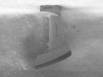
Click to zoom
Application Details
- Equipment Class
- DXX - Part 15 Low Power Communication Device Transmitter
- Date of Grant
- Aug 10, 2000
- Application Purpose
- Original Equipment
- Date of Application
- May 29, 2000
- Equipment Note
- LS 4071 Scanner
- Frequency Range
- 916.50000000 - 916.50000000
- Company
- Symbol Technologies Inc
- Country
- United States
Documents & Files
Document Text
Text extracted from the exhibit documents filed with the FCC. Open a document above to read the original.
Users Manual
The included Quick Reference guide that is Usermanual2.doc is an older version. The Quick Reference Guide is being updated to include the following: Regulatory Addendum Radio Frequency Interference Requirements This device has been tested and found to comply with the limits for a Class A digital device pursuant to Part 15 of the Federal Communications Rules and Regulation. These limits are designed to provide reasonable protection against harmful interference when the equipment is operated in a commercial environment. This equipment generates, uses, and can radiate radio frequency energy and, if not installed and used in accordance with the instruction manual, may cause harmful interference to radio communications. Operation of this equipment in a residential is likely to cause harmful interference in which case the user will be required to correct the interference at his own expense. However, there is no guarantee that interference will not occur in a particular installation. If the equipment does cause harmful interference to radio or television reception, which can be determined by turning the equipment off and on, the user is encouraged to try and correct the interference by one of the following measures: • Re-orient or relocate the receiving antenna. • Increase the separation between the equipment and receiver. • Connect the equipment into an outlet on a circuit different from that which the receiver is connected. • Consult the dealer or an experienced radio/TV technician for help. This device complies with FCC Part 15. Operation is subject to the following two conditions: (1) this device may not cause harmful interference and (2) this device must accept any interference received, including interference that may cause undesired operation.” Radio Frequency Interference Requirements- Canada This device complies with RSS 210 of Industry & Science Canada. Operation is subject to the following two conditions: (1) this device may not cause harmful interference and (2) this device must accept any interference received, including interference that may cause undesired operation.” This Class A digital apparatus meets the requirements of the Industry Canada Standard ICES-003. Cet appareil numerique de la Classe A est conforme a la norme NMB-003 du Canada. CE Marking and European Union Compliance Products intended for sale within the European Union are marked with the CE Mark which indicates compliance to applicable Directives and European Normes (EN), as follows, Amendments to these Directives or ENs are included: Applicable Directives • Electromagnetic Compatibility Directive 89/336/EEC • Low Voltage Directive 73/23/EEC Applicable Standards • EN 55022-Limits and Methods of Measurement of Radio Interference Characteristics of Information technology Equipment • EN 55024:1998; Information technology equipment-Immunity characteristics-Limits and methods of measurement. • IEC 1000-4-2(1995-01)-Electromagnetic Compatibility (EMC) – Part 4: Testing and measurement techniques-Section 2: Electrostatic Discharge immunity test. • IEC 1000-4-3(1995-03)-Electromagnetic Compatibility (EMC) –Part 4: Testing and measurement techniques-Section 3: Radiated, radio-frequency electromagnetic field immunity test. • IEC 1000-4-4(1995-01)-Electromagnetic Compatibility (EMC) –Part 4: Testing and measurement techniques-Section 4: E lectrical Fast transient /burst immunity test. • EN 60 950+Amd1 + Amd @-Safety of Information Technology Equipment Including Electrical Business Equipment • EN 60 825-1 (EN 60 825)- Safety of Devices Containing Lasers Laser Devices Symbol products using lasers comply with US 21 CFR1040.10, Subchapter J and IEC 825/EN 60 825 (or IEC 825-1/EN 60 825-1, depending on the date of manufacture). The laser classification is marked on one of the labels on the product. Class 1 Laser devices are not considered hazardous when used for their intended purpose. The following statement is required to comply with US and international regulations: Caution: Use of controls, adjustments or performance of procedures other than those specified herein may result in hazardous laser light exposure. Class 2 laser scanners use a low power visible light diode. As with any very bright light source such as the sun, the user should avoid staring directly into the light beam. Momentary exposure to a Class 2 laser is not known to be harmful. RF Devices Symbol’s RF products are designed to be compliant with the rules and regulations in the locations into which they are sold and will be labeled as required. The majority of Symbol’s RF devices are type approved and do not require the user to obtain license or authorization before using the equipment. Any changes or modifications to Symbol Technologies equipment not expressly approved by Symbol Technologies could void the user’s authority to operate the equipment. “Important Note: To comply with FCC and Industry Canada RF exposure requirements, this hand-held device is approved for operation in a user’s hand when there is 20 cm or more between the antenna and the user’s body.”
Users Manual
RS 2200/3200 Series LS 4071 Scanner Quick Reference Quick Reference © 1997 SYMBOL TECHNOLOGIES, INC. All rights reserved. Symbol reserves the right to make changes to any product to improve reliability, function, or design. Symbol does not assume any product liability arising out of, or in connection with, the application or use of any product, circuit, or application described herein. No license is granted, either expressly or by implication, estoppel, or otherwise under any patent right or patent, covering or relating to any combination, system, apparatus, machine, material, method, or process in which Symbol products might be used. An implied license only exists for equipment, circuits, and subsystems contained in Symbol products. Symbol Technologies, Inc. One Symbol Plaza Holtsville, NY 11742-1300 http://www.symbol.com This product is covered by one or more of the following U.S. and foreign Patents: U.S. Patent No. 4,360,798; 4,369,361; 4,387,297; 4,460,120; 4,496,831; 4,593,186; 4,603,262; 4,607,156; 4,652,750; 4,673,805; 4,736,095; 4,758,717; 4,816,660; 4,845,350; 4,896,026; 4,897,532; 4,923,281; 4,933,538; 4,992,717; 5,015,833; 5,017,765; 5,021,641; 5,029,183; 5,047,617; 5,103,461; 5,113,445; 5,140,144; 5,142,550; 5,149,950; 5,157,687; 5,168,148; 5,168,149; 5,180,904; 5,229,591; 5,230,088; 5,235,167; 5,243,655; 5,247,162; 5,250,791; 5,250,792; 5,262,627; 5,280,163; 5,280,164; 5,280,498; 5,304,786; 5,304,788; 5,321,246; 5,367,151; 5,373,148; 5,378,882; 5,377,361; 5,396,053; 5,396,055; 5,399,846; 5,408,081; 5,410,139; 5,410,140; 5,412,198; 5,418,812; 5,420,411; 5,436,440; 5,444,231; 5,449,891; 5,449,893; 5,468,949; 5,479,000; 5,479,002; 5,479,441; 5,504,322; 5,528,621; 5,532,469; 5,543,610; 5,545,889; 5,552,592; 5,578,810; 5,589,680; D305,885; D341,584; D344,501; D359,483; D362,435; D363,700; D363,918; D370,478. Invention No. 55,358; 62,539; 69,060; 69,187 (Taiwan); No. 1,601,796; 1,907,875; 1,955,269 (Japan). European Patent 367,299; 414,281; 367,300; 367,298; UK 2,072,832; France 81/03938; Italy 1,138,713. 1 Introduction The LS 4071 is a high performance scanner that lets you scan a bar code and transmit it to a base station up to 10 feet (3 meters) away, without a physical cable to limit your movement. Instead, the scanner communicates with the base station through a low power radio transmission. Scanning Made Easy To install the scanner or change the different programmable parameters of the LS 4071, see the Product Reference Guide . If you are using a Synapse cable, select the host type by scanning the appropriate bar code packed with the cable. If you are not using a Synapse cable, scan one of the bar codes beginning on page 6. If you need assistance, contact the technical person in charge of scanning at your site, or Symbol Technologies. Quick Reference 2 Ready, Test, Scan Ready Make sure connections are secure, and the battery pack is charged. The battery must be charged before the scanner’s initial use, and after each day’s use. Placing the scanner in its base station between uses will help maintain the battery’s charge. Be sure the scanner is “paired” to the base station by scanning the Pairing bar code on the base. Test Aim the scanner away from you and press the trigger. When you press the trigger, the scanning beam is energized for approximately 3.0 seconds (default). Scan Make sure the symbol you want to scan is within the scanning range. See the LS 4071 Product Reference Guide . Also, be certain the scanner is within range of the base station: 10 feet (3 meters). The scanner has read the symbol when: • The yellow LED on the rear of the scanner turns green for a short period of time after the scanning beam turns off. The data has been successfully sent to the base station when: • You hear a short, high tone beep from the base (if default beeper settings are selected). • The yellow LED on the base blinks. 3 Aiming Scan the Entire Symbol • Your scan beam must cross every bar and space on the symbol. • The larger the symbol, the farther away you should hold the scanner. • Hold the scanner closer for symbols with bars that are close together. • A short, high tone beep from the base indicates a good decode. RightWrong 0123456789 0123456789 Quick Reference 4 Hold at an angle Do not hold the scanner directly over the bar code. Laser light reflecting directly back into the scanner from the bar code is known as specular reflection. This strong light can “blind” the scanner and make decoding difficult. The area where specular reflection occurs is known as a “dead zone”. You can tilt the scanner up to 65 ° forward or back and still achieve a successful decode. Simple practice quickly shows what tolerances to work within. 65° Max Shaded area represents dead zone (±2°) Bar Code Scan Beam Scan Beam 65° Max 5 What Does The Beep Mean? When you hear 1 beep (short high tone) it means data has been decoded successfully. If any other beeps are heard, contact the technical person in charge of scanning. What If... If the scanner is not operating according to your needs, contact the technical person in charge of scanning. If there is no one in charge of scanning, call the Symbol Support Center at 1-800-653-5350. Quick Reference 6 Host Types When using an RL475 system, select one of the bar codes below to communicate with an IBM 468X/9X host. Port 5B Port 9B Port 17 Note: To properly communicate with 468X/9X terminals, the driver corresponding to the port being used must be loaded and enabled when you are configuring your terminal system. See your terminal’s operating manual for details. 7 Host Types RS-232C Host Types Three RS-232C hosts are set up with their own parameter default settings. Selecting the ICL, Fujitsu or Nixdorf RS-232C terminal sets the defaults listed on the following page. These defaults take precedence over Standard RS-232 defaults. So, if you’ve selected Fujitsu RS-232C, then select the Standard RS-232 defaults, the Fujitsu defaults still take precedence. To return to the…
Text truncated - open the document above for the full version.
Attestation Statements
Sandy Mazzola Symbol Technologies, Inc. 1 Symbol Plaza Holtsville, N.Y. 11742 Voice : (516) 738-5373 Fax: (516) 738-3318 Letter of Confidentiality Request Dear Reviewer, Symbol Technologies (“Symbol”), requests that the Block Diagram, Schematics, and operational Description exhibits of the referenced application be withheld from routine availability for public inspection pursuant to Section 0.459 of the Commissions Rules an Freedom of Information Act (“FOIA) Exemption 4, 5 U.S.C. 552 (b) (4). These exhibits consist of “trade secrets (or) commercial or financial information obtained from a person and privileged or confidential” 5 U.S.C. 552 (b) (4), and is therefore entitled to protection from disclosure under FOIA. The documents in question contain trade secrets: detailed technical descriptions, specifications and schematics for a product to be offered for sale. These materials provide particulars on the product design. This information would give Symbol’s competitors an unearned and unwarranted competitive advantage. The documents contain “commercial information” within the scope of FOIA exemption 4. This information is the product of Symbol’s investment of money, personnel, and other resources. The result of the investment is a fairly earned position in the marketplace. Premature release of the information threatens substantial and unwarranted harm to Symbol’s competit ive posit ion. For these reasons, Symbol has taken pains to keep this technical information confidential, and intends to continue doing so. Symbol customarily witholds this information from persons outside the employ of Symbol and certain of its suppliers and contractors, and even within these groups routinely limits access to persons having a particular need for the information. If the Commissions were to make these documents public, it would be giving away hard won fruits of Symbols labors without compensation. The filing fee that is required for this confidentiality request is included in the check that accompanies this application. If there are any questions about this request, please call me at the number above. Thank you for your attention. Respectfully submitted, Sandy Mazzola
ID Label/Location Info
Sample FCC Label Symbol Technologies Inc. FCC ID: H9PLS4071ITA This device complies with Part 15 of the FCC rules. Operation is subject to the following two conditions: (1) this device may not cause harmful interference and (2) this device must accept any interference received, including interference that may cause undesired operation. This is a sample draft of the label that will be located on the underside of the product. Sandy Mazzola
Operational Description
LS4071 Antenna Information Response to FCC inquiry regarding antenna gain information for FCC ID: H9PLS4071ITA. Also included are two PDF files. One contains polar plots of the antenna and the other is the released drawing of the antenna. The antenna is a printed wire flex type that has an antenna gain of < 0 dBi. Sandy Mazzola Symbol Technologies Inc 1 Symbol Plaza Holtsville, N.Y. 11742-1300 Phone: (631) 738-5373 Fax: (631) 738-3915 or (631) 738-3318 E-mail: [email protected]
Test Report
APPLICANT Symbol Technologies, Inc. One Symbol Plaza Holtsville, NY 11742 Manufacturer Symbol Technologies, Inc. One Symbol Plaza Holtsville, NY 11742 TEST SPECIFICATION:FCC Rules and Regulations Part 15, Subpart C TEST PROCEDURE:FCC 15.249(a) TEST SAMP LE DESCRIP TION BRANDNAME:Symbol MODEL:LS4071FCC ID: H9PLS4071ITA TYPE:916.5 MHz Pulsed RF Transmitter FREQUENCY RANGE:902-928 MHz POWER REQUIREMENTS: Fresh 6 VDC Battery TESTS P ERFORMED - 15.209(a)Radiated Emissions, Spurious Case - 15.249(a)Radiated Emissions, Fundamental and Harmonics - 15.249(c)Occupied Bandwidth REPORT OF MEASUREMENTS Applicant:Symbol Technologies, Inc.. Device:Pulsed RF Transmitter FCC ID:H9PLS4071ITA Power Requirements:Fresh 6 VDC Battery Applicable Rule Section:Part 15, Subpart C, Section 15.249 TEST RESULTS 15.249(a):Field strength of emissions from the intentional radiator operating in the 902-928 MHz frequency band did not exceed 50 mV/m average for the fundamental and 500 uV/m average for harmonics. 15.249(b):Field strength readings were recorded at a distance of three meters from the Intentional Radiator unless otherwise specified. 15.249(c):Emissions radiated outside the specified frequency band except for harmonics, were attenuated by at least 50dB or to the emissions limits of 15.209, whichever was the lesser attenuation. 15.249(d):All measurements were taken utilizing a peak detector. The peak field strength did not exceed the average limits under any condition of modulation. GENERAL NOTES 1.All user accessible controls were adjusted to produce maximum emissions. 2.The unit operates in the band of 902-928 MHz band at a single frequency of 916.5 MHz. 3.The frequency range was scanned from 30 MHz to 9.2 GHz. All emissions not reported were more than 20dB below the specified limit. EXHIBIT 4 Radiated Emissions, Spurious Case Para. 15.209(a) (Please see separate e-file attachment named RE Spurious.doc) EXHIBIT 4 Radiated Emissions, Fundamental & Harmonic Para. 15.249(a) (Please see separate e-file attachment named REFundHarm.doc) EXHIBIT 4 Occupied Bandwidth Para. 15.249(c) (Please see separate e-file attachment named OccBw.pdf) EQUIPMENT LISTS FCC15.209(a) Radiated Emissions, Spurious, 30MHZ to 9.2GHz ENTypeManufacturerDescription.Model No.Cal Date Due Date 062High Gain Horn AntennaMicrolab/FXR1.7 GHz - 2.6 GHzR638A01/25/200001/25/2001 063High Gain Horn AntennaMicrolab/FXR2.6 GHz-3.95 GHzS638A01/26/200001/26/2001 064High Gain Horn AntennaMicrolab/FXR3.95 GHz - 5.85 GHzH638A01/26/200001/26/2001 065High Gain Horn AntennaMicrolab/FXR5.85 GHz - 8.2 GHzC638A01/26/200001/26/2001 066High Gain Horn AntennaMicrolab/FXR8.2 GHz - 12.4 GHzX638A01/26/200001/26/2001 067Open Area Test SiteRetlif3 MeterRNY10/15/199710/15/2000 133Broadband Pre-AmplifierElectro-Metrics10 kHz - 1 GHz, 26dBBPA-100006/22/199906/22/2000 141Spectrum AnalyzerHewlett Packard100 Hz - 40 GHz8566B03/20/200009/20/2000 141AGraphics PlotterHewlett PackardN/A7470A03/08/200003/08/2001 141BQuasi-Peak AdaptorHewlett Packard100 Hz - 1 GHz85650A03/20/200009/20/2000 206B6.0 dB AttenuatorTexscan0 - 1.0 GHzFP-50 - 6 dB06/22/199906/22/2000 523BiconilogElectro-Mechanics26 - 2000 MHz3142B10/22/199805/22/2000 543PreamplifierHewlett Packard1.0 GHz - 26.5 GHz8449B06/16/199906/16/2001 617Interference AnalyzerElectro-Metrics10 kHz - 1 GHzEMC-3001/17/200001/17/2001 FCC15.249(a) Fundamental and Harmonics, 30MHz to 9.2GHz ENTypeManufacturerDescription.Model No.Cal Date Due Date 062High Gain Horn AntennaMicrolab/FXR1.7 GHz - 2.6 GHzR638A01/25/200001/25/2001 063High Gain Horn AntennaMicrolab/FXR2.6 GHz-3.95 GHzS638A01/26/200001/26/2001 064High Gain Horn AntennaMicrolab/FXR3.95 GHz - 5.85 GHzH638A01/26/200001/26/2001 065High Gain Horn AntennaMicrolab/FXR5.85 GHz - 8.2 GHzC638A01/26/200001/26/2001 066High Gain Horn AntennaMicrolab/FXR8.2 GHz - 12.4 GHzX638A01/26/200001/26/2001 067Open Area Test SiteRetlif3 MeterRNY10/15/199710/15/2000 133Broadband Pre-AmplifierElectro-Metrics10 kHz - 1 GHz, 26dBBPA-100006/22/199906/22/2000 141Spectrum AnalyzerHewlett Packard100 Hz - 40 GHz8566B03/20/200009/20/2000 141AGraphics PlotterHewlett PackardN/A7470A03/08/200003/08/2001 141BQuasi-Peak AdaptorHewlett Packard100 Hz - 1 GHz85650A03/20/200009/20/2000 206B6.0 dB AttenuatorTexscan0 - 1.0 GHzFP-50 - 6 dB06/22/199906/22/2000 523BiconilogElectro-Mechanics26 - 2000 MHz3142B10/22/199805/22/2000 543PreamplifierHewlett Packard1.0 GHz - 26.5 GHz8449B06/16/199906/16/2001
Test Report
Retlif Testing Laboratories R Data Sheet 1 of 2 Test Method: FCC Part 15 Subpart C Radiated Emissions, Fundamental & Harmonic Emissions Customer: Symbol Technologies Job No. R-8504-1 Test Sample: 916.5MHz Pulsed RF Transmitter Paragraph: 249(a) Model No.: LS4071 FCC ID: H9PLS4071ITA Operating Mode: Continuously Transmitting a 916.5MHz Signal Technician: P. Lananna Date : May 1, 2000 Note s: Test Distance: 3 Meters Detector: Peak, Unless otherwise specified Test Freq. Antenna Pol./Height EUT Orientation Meter Reading Correction Factor Corrected Reading Converted Reading Avg. Li mi t MH z( V/ H) / Me te r sX / Y / ZdBuVdBdBuV/ muV/ muV/ m 916.5H / 2.0X72.07.3 79.39225.7 50000 |H / 2.3Y77.67.3 84.917579.2 | |H / 1.0Z75.77.3 83.014125.4 | |V / 1.0X76.97.3 84.216218.1 | |V / 1.0Y76.07.3 83.314621.8 | 916.5V / 1.0Z73.67.3 80.911091.7 50000 1833H / 1.0X38.0-8.8 29.228.8* 500 |H / 1.0Y38.0-8.8 29.228.8* | |H / 1.0Z38.0-8.8 29.228.8* | |V / 1.0X38.0-8.8 29.228.8* | |V / 1.0Y38.0-8.8 29.228.8* | 1833V / 1.0Z38.0-8.8 29.228.8* 500 2749.5H / 1.0X37.0-8.3 28.727.2* 500 |H / 1.0Y37.0-8.3 28.727.2* | |H / 1.0Z37.0-8.3 28.727.2* | |V / 1.0X37.0-8.3 28.727.2* | |V / 1.0Y37.0-8.3 28.727.2* | 2749.5V / 1.0Z37.0-8.3 28.727.2* 500 3666H / 1.0X37.0-7.2 29.830.9* 500 |H / 1.0Y37.0-7.2 29.830.9* | |H / 1.0Z37.0-7.2 29.830.9* | |V / 1.0X37.0-7.2 29.830.9* | |V / 1.0Y37.0-7.2 29.830.9* | 3666V / 1.0Z37.0-7.2 29.830.9* 500 4582.5H / 1.0X38.0-3.3 34.754.3* 500 |H / 1.0Y38.0-3.3 34.754.3* | |H / 1.0Z38.0-3.3 34.754.3* | |V / 1.0X38.0-3.3 34.754.3* | |V / 1.0Y38.0-3.3 34.754.3* | 4582.5V / 1.0Z38.0-3.3 34.754.3* 500 The frequency range was scanned from 30 MHz to 9.2 GHz. All emissions not recorded were more Than 10 dB below the specified limit. Emissions from the EUT do not exceed the specified limits. *=Noise Floor Measurements (Minimum system sensitivity) Retlif Job Number R-8504-1 Retlif Testing Laboratories R Data Sheet 2 of 2 Test Method: FCC Part 15 Subpart C Radiated Emissions, Fundamental & Harmonic Emissions Customer: Symbol Technologies Job No. R-8504-1 Test Sample: 916.5MHz Pulsed RF Transmitter Paragraph: 249(a) Model No.: LS4071 FCC ID: H9PLS4071ITA Operating Mode: Continuously Transmitting a 916.5MHz Signal Technician: P. Lananna Date : May 1, 2000 Note s: Test Distance: 3 Meters Detector: Peak, unless otherwise specified Test Freq. Antenna Pol./Height EUT Orientation Meter Reading Correction Factor Corrected Reading Converted Reading Avg. Li mi t MH z( V/ H) - Me te r sX / Y / ZdBuVdBdBuV/ muV/ muV/ m 5499H / 1.0X36.0-3.1 32.944.2* 500 |H / 1.0Y36.0-3.1 32.944.2* | |H / 1.0Z36.0-3.1 32.944.2* | |V / 1.0X36.0-3.1 32.944.2* | |V / 1.0Y36.0-3.1 32.944.2* | 5499V / 1.0Z36.0-3.1 32.944.2* 500 6415.5H / 1.0X36.0-0.5 35.559.6* 500 |H / 1.0Y36.0-0.5 35.559.6* | |H / 1.0Z36.0-0.5 35.559.6* | |V / 1.0X36.0-0.5 35.559.6* | |V / 1.0Y36.0-0.5 35.559.6* | 6415.5V / 1.0Z36.0-0.5 35.559.6* 500 7332H / 1.0X34.0-2.1 31.939.4* 500 |H / 1.0Y34.0-2.1 31.939.4* | |H / 1.0Z34.0-2.1 31.939.4* | |V / 1.0X34.0-2.1 31.939.4* | |V / 1.0Y34.0-2.1 31.939.4* | 7332V / 1.0Z34.0-2.1 31.939.4* 500 8248.5H / 1.0X36.0-0.5 35.559.6* 500 |H / 1.0Y36.0-0.5 35.559.6* | |H / 1.0Z36.0-0.5 35.559.6* | |V / 1.0X36.0-0.5 35.559.6* | |V / 1.0Y36.0-0.5 35.559.6* | 8248.5V / 1.0Z36.0-0.5 35.559.6* 500 9165H / 1.0X35.02.0 37.070.8* 500 |H / 1.0Y35.02.0 37.070.8* | |H / 1.0Z35.02.0 37.070.8* | |V / 1.0X35.02.0 37.070.8* | |V / 1.0Y35.02.0 37.070.8* | 9165V / 1.0Z35.02.0 37.070.8* 500 The frequency range was scanned from 30 MHz to 9.2 GHz. All emissions not recorded were more Than 10 dB below the specified limit. Emissions from the EUT do not exceed the specified limits. *= Noise Floor Measure me nts ( Mi ni mum sys te m se nsitivity) Retlif Job Number R-8504-1 Retlif Testing Laboratories R Data Sheet 3 of 2 Test Method: FCC Part 15 Subpart C Radiated Emissions, Fundamental & Harmonic Emissions Customer:Job No. Test Sample:Paragraph: Mode l No.:FCC ID: Operating Mode: Continuously Transmitting a MHz Signal Technician:Date: Note s: Test Distance: 3 MetersDuty Cycle: Detector: Peak, unless otherwise specifiedDuty Cycle Correction: - dB Test Freq. Antenna Pol./Height EUT Orientation Peak Reading Correction Factor Corrected Reading Converted Reading Avg. Li mi t MH z( V/ H) - Me te r sX / Y / ZdBuVdBdBuV/ muV/ muV/ m H /X |H / Y| |H / Z| |V / X| |V / Y| V /Z H /X |H / Y| |H / Z| |V / X| |V / Y| V /Z H /X |H / Y| |H / Z| |V / X| |V / Y| V /Z H /X |H / Y| |H / Z| |V / X| |V / Y| V /Z H /X |H / Y| |H / Z| |V / X| |V / Y| V /Z The frequency range was scanned from 30 MHz to XX GHz. All emissions not recorded were more Than 10 dB below the specified limit. Emissions from the EUT do not exceed the specified limits. *= Noise Floor Measure me nts ( Mi ni mum sys te m se nsitivity) Retlif Job Number R- Retlif Testing Laboratories R Data Sheet 4 of 2 Test Method: FCC Part 15 Subpart C Radiated Emissions, Fundamental & Harmonic Emissions Customer:Job No. Test Sample:Paragraph: Mode l No.:FCC ID: N/A Operating Mode: Continuously Transmitting a MHz Signal Technician:Date: Note s: Test Distance: 3 MetersDuty Cycle: Detector: Peak, unless otherwise specifiedDuty Cycle Correction: - dB Test Freq. Antenna Pol./Height EUT Orientation Peak Reading Correction Factor Corrected Reading Converted Reading Avg. Li mi t MH z( V/ H) - Me te r sX / Y / ZdBuVdBdBuV/ muV/ muV/ m H /X |H / Y| |H / Z| |V / X| |V / Y| V /Z H /X |H / Y| |H / Z| |V / X| |V / Y| V /Z H /X |H / Y| |H / Z| |V / X| |V / Y| V /Z H /X |H / Y| |H / Z| |V / X| |V / Y| V /Z H /X |H / Y| |H / Z| |V / X| |V / Y| V /Z The frequency range was scanned from 30 MHz to XX GHz. All emissions not recorded were more Than 10 dB below the specified limit. Emissions from the EUT do not exceed the specified limits. *= Noise Floor Measure me nts ( Mi ni mum sys te m se nsitivity) Retlif Job Number R-
Test Report
Retlif Testing Laboratories R Retlif Job Number R-8504-1 Data Sheet 1 of 1 Test Method: FCC Part 15 Subpart C, Spurious Case Radiated Emissions, Paragraph 15.209(a) Customer: Symbol Technologies Job No. R-8504-1 Test Sample: 916.5MHz Pulsed RF Transmitter FCC ID. H9PLS4071ITA Model No.: LS4071 Serial No. N/ A Operating Mode: Continuously Transmitting a 916.5MHz Signal Technician: P. Lananna Date: May 2, 2000 Notes: Test Distance: 3 Meters Temp: 13 C Humidity: 37% Detector: Quasi-Peak Below 1 GHz, Peak above 1 GHz Test Freq. Antenna Position EUT Orientation Meter Readings Correction Factor Corrected Reading Converted Reading LIMIT MHz (V/H) / Meters Degrees dBuV dB dBuV/m uV/m uV/m 30.00100 || || || || || || 88.00100 88.00150 l| 216.00150 216.00200 || || || 810.5V/1.3180395.744.7171.8| 819.5V/1.3180385.943.9156.7| 828.0V/1.0180386.042.0125.9| || || || l| 960.00200 960.00500 l| || l| 9200.0500 The EUT was scanned from 30 MHz to 9.2GHz The emissions observed from the EUT do not exceed the specified limits. Emissions not recorded were more than 10dB under the specified limit
Contact Information
Applicant
Qianlin Zhou(Regulatory Specialist)
Technical Contact
Retlif Testing LaboratoriesThomas J Schneider
[email protected]631-737-1500
795 Marconi Avenue · Ronkonkoma, New York · United States
Non-Technical Contact
Retlif Testing LaboratoriesMichelle Tirado
[email protected]631-737-1500
Technical Specifications
| # | Rule Parts | Frequency Range | Power Output |
|---|---|---|---|
| 1 | 15.249 | 916.5 MHz - 916.5 MHz | - |
Other Applications from Symbol Technologies Inc

H9PCCHUB1
Jun 30, 2015Customer Concierge
Equipment Class
NII - Unlicensed National Information Infrastructure TX
H9PAP7562
May 10, 2015802.11 abgn/ac Access Point
Equipment Class
DTS - Digital Transmission System
H9PTC75AH
Mar 26, 2015Touch Computer
Equipment Class
NII - Unlicensed National Information Infrastructure TX
H9PRA1202
Sep 24, 2014UHF Narrowband Radio Module
Equipment Class
TNB - Licensed Non-Broadcast Station Transmitter
H9PEMG101
Aug 26, 2014802.15.4 Gateway
Equipment Class
DTS - Digital Transmission System