H9PMC75A6EDA (Enterprise Digital Assistant)
Symbol Technologies Inc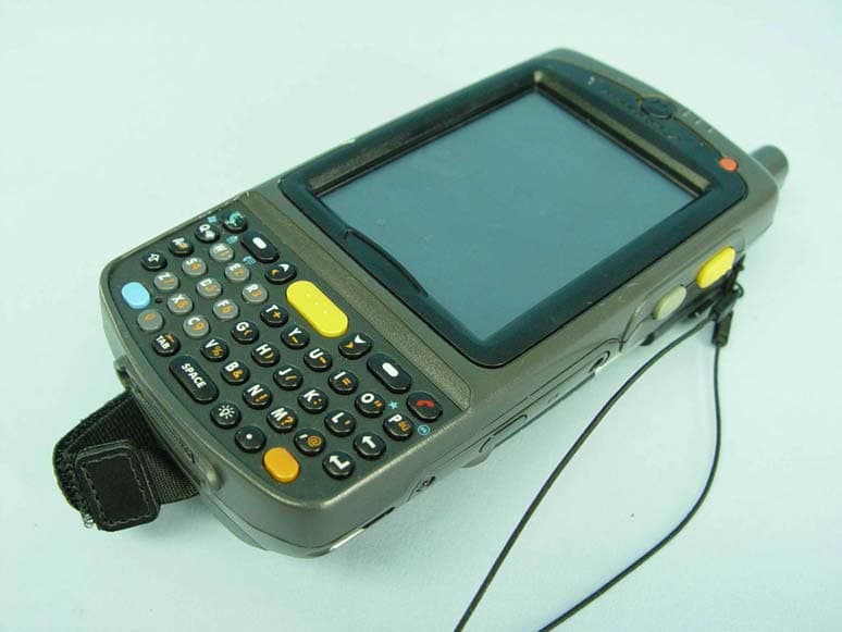
Click to zoom
Application Details
- Equipment Class
- NII - Unlicensed National Information Infrastructure TX
- Date of Grant
- Jun 13, 2010
- Application Purpose
- Original Equipment
- Date of Application
- Jun 13, 2010
- Equipment Note
- EDA (Enterprise Digital Assistant)
- Frequency Range
- 5500.00000000 - 5700.00000000
- Company
- Symbol Technologies Inc
- Country
- United States
Documents & Files
Document Text
Text extracted from the exhibit documents filed with the FCC. Open a document above to read the original.
Users Manual
MC75A Enterprise Digital Assistant User Guide DRAFT DRAFT MC75A Enterprise Digital Assistant User Guide 72E-133503-01 Rev. A February 2010 DRAFT ii MC75A Enterprise Digital Assistant User Guide © 2010 by Motorola, Inc. All rights reserved. No part of this publication may be reproduced or used in any form, or by any electrical or mechanical means, without permission in writing from Motorola. This includes electronic or mechanical means, such as photocopying, recording, or information storage and retrieval systems. The material in this manual is subject to change without notice. The software is provided strictly on an “as is” basis. All software, including firmware, furnished to the user is on a licensed basis. Motorola grants to the user a non-transferable and non-exclusive license to use each software or firmware program delivered hereunder (licensed program). Except as noted below, such license may not be assigned, sublicensed, or otherwise transferred by the user without prior written consent of Motorola. No right to copy a licensed program in whole or in part is granted, except as permitted under copyright law. The user shall not modify, merge, or incorporate any form or portion of a licensed program with other program material, create a derivative work from a licensed program, or use a licensed program in a network without written permission from Motorola. The user agrees to maintain Motorola’s copyright notice on the licensed programs delivered hereunder, and to include the same on any authorized copies it makes, in whole or in part. The user agrees not to decompile, disassemble, decode, or reverse engineer any licensed program delivered to the user or any portion thereof. Motorola reserves the right to make changes to any software or product to improve reliability, function, or design. Motorola does not assume any product liability arising out of, or in connection with, the application or use of any product, circuit, or application described herein. No license is granted, either expressly or by implication, estoppel, or otherwise under any Motorola, Inc., intellectual property rights. An implied license only exists for equipment, circuits, and subsystems contained in Motorola products. MOTOROLA and the Stylized M Logo and Symbol and the Symbol logo are registered in the US Patent & Trademark Office. Bluetooth is a registered trademark of Bluetooth SIG. Microsoft, Windows and ActiveSync are either registered trademarks or trademarks of Microsoft Corporation. All other product or service names are the property of their respective owners. Motorola, Inc. One Motorola Plaza Holtsville, New York 11742-1300 http://www.motorola.com/enterprisemobility Patents This product is covered by one or more of the patents listed on the website: http://www.motorola.com/ enterprisemobility/patents. DRAFT iii Revision History Changes to the original manual are listed below: ChangeDateDescription -01 Rev. A02/2010Initial release. DRAFT iv MC75A Enterprise Digital Assistant User Guide DRAFT Table of Contents Patents.................................................................................................................................................. ii Revision History .................................................................................................................................... iii About This Guide Introduction ........................................................................................................................................... xiii Documentation Set xiii Configurations....................................................................................................................................... xiv Software Versions xiv Chapter Descriptions ............................................................................................................................ xvi Notational Conventions......................................................................................................................... xvii Related Documents .............................................................................................................................. xvii Service Information ............................................................................................................................... xviii Chapter 1: Getting Started Introduction .......................................................................................................................................... 1-1 Unpacking ............................................................................................................................................ 1-2 Getting Started ..................................................................................................................................... 1-2 Installing the SIM Card ................................................................................................................... 1-3 Installing the Main Battery .............................................................................................................. 1-4 Charging the Battery ...................................................................................................................... 1-5 Charging the Main Battery and Memory Backup Battery ......................................................... 1-5 Charging Spare Batteries ......................................................................................................... 1-7 Charging Temperature ............................................................................................................. 1-7 Powering On the MC75A ............................................................................................................... 1-7 Calibrating the Screen ................................................................................................................... 1-7 Checking Battery Status ......................................................…
Text truncated - open the document above for the full version.
Users Manual
Using the MC75A 2 - 17 Resetting the MC75A There are two reset functions, warm boot and cold boot. A warm boot restarts the MC75A by closing all running programs. A cold boot also restarts the MC75A, and also resets the clock. Data saved in flash memory or a memory card is not lost. If the MC75A is not functioning properly, perform a warm boot first. If the MC75A still does not respond, perform a cold boot. Performing a Warm Boot Hold down the Power button for approximately five seconds. As soon as the MC75A starts to boot release the Power button. Figure 2-16 Warm Boot Splash Screen Performing a Cold Boot To perform a cold boot simultaneously press the Power button and the 1 and 9 keys. Figure 2-17 Cold Boot Splash Screen DRAFT 2 - 18 MC75A Enterprise Digital Assistant User Guide Waking the MC75A The wake-up conditions define what actions wake up the mobile computer after it has gone into suspend mode. The mobile computer can go into suspend mode by either pressing the Power button or automatically by Control Panel time-out settings. These settings are configurable and the factory default settings are shown in are subject to change/update. Locking the MC75A Use the Device Lock feature to prevent use of the device. Note that when locked, the MC75A does not respond to screen or keypad input. To lock the MC75A, tap Start > Lock. The Lock screen appears. To unlock the MC75A, side the Lock button to the left or right. Table 2-6 Wake-up Default Settings Condition for Wake-upPower ButtonAutomatic Time-out AC power is applied.NoYes Mobile computer is inserted into a cradle.NoYes Mobile computer is removed from a cradle.NoYes Mobile computer is connected to a USB device.NoYes Mobile computer is disconnected from a USB device.NoYes A key is pressed.NoYes The scan triggered is pressed.NoYes The screen is touched.NoNo Audio JackNoNo Audio BtnNoNo Bluetooth communicationYesYes Incoming phone callYesYes On motionNoYes DRAFT Using the MC75A 2 - 19 Figure 2-18 Unlock Device Window If the MC75A was locked with a password, a prompt appears for the password. Password Locking Use the Password window to set a password to disable unauthorized access to the MC75A. 1.Ta p Start > Settings > Lock icon > Password tab. Figure 2-19 Password Window - Password Tab 2.Select Prompt if device unused for check box to enable password protection. 3.From the drop-down list, select a time value for the protection to take affect after non-use. 4.From the Password type: drop-down list, select either Simple PIN or Strong alphanumeric. 5.For a simple password, enter a four-digit password in the Password field. For a stronger password: a.Enter a seven character password in the Password: field. A strong password must contain at least seven characters and contain at least three of the following: uppercase and lowercase letters, numerals, and punctuation. NOTEIf the device is configured to connect to a network, use a strong (difficult to figure out) password to help protect network security. Password cracking tools continue to improve and the computers used to crack passwords are more powerful than ever. DRAFT 2 - 20 MC75A Enterprise Digital Assistant User Guide b.Re-enter the password in the Confirm: field. 6.Ta p OK. 7.To set a hint to remember the password, tap the Hint tab. 8.In the text box, enter a hint for a password reminder. 9.Ta p OK. When the MC75A is not used for a period of time and the user tries to access the device, the Password window appears. This also appears when the MC75A is connected to a host computer with either a cradle or communication cable. Figure 2-20 Enter Password Windows Enter the password to un-lock the device. Tap the Unlock button to unlock the device and go to the Today screen, or tap the Contact button to unlock the device and go to the Contacts window or tap the Email button to unlock the device and go to the Messaging window. Function Buttons The MC75A’s buttons perform certain functions. NOTEYou can make emergency calls even when the MC75A is locked. See for more information. DRAFT Using the MC75A 2 - 21 Figure 2-21 Function Buttons •Power: Press the red Power button to turn the MC75A screen on and off. The MC75A is in suspend mode when the screen is off. For more information, see Powering On the MC75A on page 1-7. Also use the Power button to reset the MC75A by performing a warm or cold boot. See Resetting the MC75A on page 2-17. •Scan/Action: Press to scan bar codes or capture images. See Chapter 3, Data Capture. Or, press to open an application or perform a function. See the Microsoft ® Applications for Mobile 6 User Guide to set an application to open. •Up/Down: Press to increase or decrease the MC75A’s volume. •Action: Press to open an application or perform a function. See the Microsoft ® Applications for Mobile 6 User Guide to set an application to open. Stylus Use the MC75A stylus to select items and enter information. The stylus functions as a mouse. •Tap: Touch the screen once with the stylus to press option buttons and open menu items. •Tap and Hold: Tap and hold the stylus on an item to see a list of actions available for that item. On the pop-up menu that appears, tap the action to perform. •Drag: Hold the stylus on the screen and drag across the screen to select text and images. Drag in a list to select multiple items. Scan/Action Button Power Button Up/Down Button Action Button Scan/Action Button NOTEMotorola recommends using the spring-loaded tip of the stylus to write on the screen, and the back end of the stylus to tap the screen. Use your finger to press the Power button and keypad buttons. CAUTIONTo prevent damage to the screen, do not use any device other than the Motorola-provided stylus. DRAFT 2 - 22 MC75A Enterprise Digital Assistant User Guide Entering Data When entering data on the keypad, use either the single-hand method or the two-hand method as shown in Figure 2-22. Figure 2-22 Entering Data on the Keypad Single-hand Method Two-hand Method DRAFT Using the MC75A 2…
Text truncated - open the document above for the full version.
Users Manual
Using Bluetooth 6 - 3 Bluetooth Configuration By default, the MC75A is configured to using the Microsoft Bluetooth stack. Refer to the MC75A Mobile Computer Integrator Guide, Appendix B, for information on switching to the StoneStreet One Bluetooth stack. Table 6-1 list the services supported by the Microsoft Bluetooth stack and the StoneStreet One Bluetooth stack. Table 6-2 list the COM ports available for the Microsoft Bluetooth stack and the StoneStreet One Bluetooth stack. Bluetooth Power States Cold Boot With StoneStreet One Bluetooth Stack Performing a cold boot on the MC75A turns off Bluetooth after initialization (which takes a few moments). It is normal to see the Bluetooth icon appear and disappear (when using the Classic Home screen), as well as a wait cursor, when initialization proceeds in all modes. Table 6-1 Bluetooth Services Microsoft Bluetooth StackStoneStreet One Bluetooth Stack OBEX Object Push ServicesOBEX Object Push Services Hands-Free Audio Gateway ServicesHands-Free Audio Gateway Services Serial Port ServicesSerial Port Services Personal Area Networking ServicesPersonal Area Networking Services PBAP ServicesIrMC Services Dial-Up Networking ServicesDial-Up Networking Services HID Client ServicesHID Client Services A2DP/AVRCP ServicesA2DP/AVRCP Services File Transfer Services Headset Audio Gateway Services Table 6-2 COM Ports Microsoft Bluetooth StackStoneStreet One Bluetooth Stack COM5COM5 COM9COM9 COM11 COM21 COM22 COM23 DRAFT 6 - 4 MC75A Enterprise Digital Assistant User Guide With Microsoft Bluetooth Stack Performing a cold boot retain the state of the Bluetooth radio prior to the cold boot. Warm Boot With StoneStreet One Bluetooth Stack Performing a warm boot on the MC75A turns off Bluetooth. With Microsoft Bluetooth Stack Performing a warm boot retain the state of the Bluetooth radio prior to the warm boot. Suspend When there is an active Bluetooth connection, the Bluetooth radio goes into low power mode maintaining the active connection. When there is no active connection, the Bluetooth radio turns off. With StoneStreet One Bluetooth Stack With Microsoft Bluetooth Stack Resume When the MC75A resumes, Bluetooth turns on if it was on prior to suspend. Using Microsoft Bluetooth Stack The following sections provide information on using the Microsoft Bluetooth stack. Turning the Bluetooth Radio Mode On and Off Turn off the Bluetooth radio to save power or if entering an area with radio restrictions (e.g., an airplane). When the radio is off, other Bluetooth devices cannot see or connect to the MC75A. Turn on the Bluetooth radio to exchange information with other Bluetooth devices (within range). Communicate only with Bluetooth radios in close proximity. Enabling Bluetooth To enable Bluetooth: NOTEIf there is an active Bluetooth connection between the MC75A and another Bluetooth device, the MC75A will not timeout. However, if the user presses the Power button on the MC75A, the MC75A will suspend (except when on a call) and upon receiving data from a remote Bluetooth device, the MC75A will wake from suspend mode. For example, headset redial or Bluetooth scanner sending data to the MC75A. NOTEIf there is an active Bluetooth connection between the MC75A and another Bluetooth device and there is no data activity, the MC75A will timeout. However, if the user presses the Power button on the MC75A, the MC75A will suspend (except when on a call) and upon receiving data from a remote Bluetooth device, the MC75A will wake from suspend mode. For example, headset redial or Bluetooth scanner sending data to the MC75A. NOTETo achieve the best battery life turn off radios not in use. DRAFT Using Bluetooth 6 - 5 1.Ta p Wireless Manager and then tap the Bluetooth bar or Ta p Start > Setting > Connections > Bluetooth icon > Mode tab. Figure 6-1 Bluetooth Mode Tab 2.Check the Turn On Bluetooth checkbox. 3.Ta p OK. Disabling Bluetooth To disable Bluetooth: 1.Ta p Wireless Manager and then tap the Bluetooth bar or Ta p Start > Setting > Connections > Bluetooth icon > Mode tab. 2.Un-check the Turn On Bluetooth checkbox. 3.Ta p OK. Discovering Bluetooth Device(s) The MC75A can receive information from discovered devices without bonding. However, once bonded, the MC75A and a bonded device exchange information automatically when you turn the Bluetooth radio on. See Bonding with Discovered Device(s) on page 6-32 for more information. To find Bluetooth devices in the area: 1.Ensure that Bluetooth is enabled on both devices. 2.Ensure that the Bluetooth device to discover is in discoverable and connectable modes. 3.Ensure that the two devices are within 30 feet (10 meters) of one another. 4.Ta p Start > Settings > Connections tab > Bluetooth icon > Devices tab. DRAFT 6 - 6 MC75A Enterprise Digital Assistant User Guide Figure 6-2 Bluetooth - Devices Tab 5.Ta p Add new device. The MC75A begins searching for discoverable Bluetooth devices in the area. Figure 6-3 Searching for Bluetooth Devices 6.Select a device from the list. Figure 6-4 Select a Bluetooth Device 7.Ta p Next. The Enter Passcode window appears. NOTEIf Smart-pairing is configured and the device is requesting one of the pre-defined PINs, the Enter Passcode window does not appear. DRAFT Using Bluetooth 6 - 7 Figure 6-5 Enter Passcode 8.Enter the Passcode on the other device. The device is added to the Bluetooth list. Figure 6-6 Bluetooth Connection Confirmation You are prompted to enter a passcode. If the device has a specific passcode, enter it in the Passcode field and tap Next. If the device does not have a specific passcode, enter a passcode in the Passcode field and tap Next. The Bluetooth radio tries to connect with the device. 9.If you created a passcode, you will be prompted by the other device to enter the same passcode. Enter the created passcode to establish a paired connection. (If you entered a passcode from the device, you shouldn’t have to do anything on the other device.) 10.When the connection is complete, a list of …
Text truncated - open the document above for the full version.
Users Manual
Accessories 7 - 5 Four Slot Ethernet Cradle This section describes how to set up and use a Four Slot Ethernet cradle with the MC75A. For cradle communication setup procedures refer to the MC75A Integrator Guide. The Four Slot Ethernet cradle: •Provides 5.4 VDC power for operating the MC75A. •Connects the MC75A (up to four) to an Ethernet network. •Simultaneously charges up to four MC75A devices. Charging Insert the MC75A into a slot to begin charging. Figure 7-3 MC75A Battery Charging Battery Charging Indicators The MC75A’s charge LED shows the status of the battery charging in the MC75A. See Table 1-2 on page 1-7 for charging status indications. The 3600 mAh battery fully charges in less than five hours and the 4800 mAh battery fully charges in less than seven hours. DRAFT 7 - 6 MC75A Enterprise Digital Assistant User Guide Charging Temperature Charge batteries in temperatures from 0°C to 40°C (32°F to 104°F). Charging is intelligently controlled by the MC75A. To accomplish this, for small periods of time, the MC75A or accessory alternately enables and disables battery charging to keep the battery at acceptable temperatures. The MC75A or accessory indicates when charging is disabled due to abnormal temperatures via its LED. See Table 1-2 on page 1-7. DRAFT Accessories 7 - 7 Four Slot Charge Only Cradle This section describes how to set up and use a Four Slot Charge Only cradle with the MC75A. The Four Slot Charge Only cradle: •Provides 5.4 VDC power for operating the MC75A. •Simultaneously charges up to four MC75A devices. Charging Insert the MC75A into a slot to begin charging. Figure 7-4 MC75A Battery Charging Battery Charging Indicators The MC75A’s charge LED shows the status of the battery charging in the MC75A. See Table 1-2 on page 1-7 for charging status indications. The 3600 mAh battery fully charges in less than five hours and the 4800 mAh battery fully charges in less than seven hours. Charging Temperature Charge batteries in temperatures from 0°C to 40°C (32°F to 104°F). Charging is intelligently controlled by the MC75A. DRAFT 7 - 8 MC75A Enterprise Digital Assistant User Guide To accomplish this, for small periods of time, the MC75A or accessory alternately enables and disables battery charging to keep the battery at acceptable temperatures. The MC75A or accessory indicates when charging is disabled due to abnormal temperatures via its LED. See Table 1-2 on page 1-7. DRAFT Accessories 7 - 9 VCD7X00 Vehicle Cradle This section describes how to use a VCD7X00 vehicle cradle with the MC75A. For cradle installation and communication setup procedures refer to the MC75A Integrator Guide. Once installed in a vehicle, the cradle: •holds the MC75A securely in place •provides power for operating the MC75A •provides a serial port for data communication between an MC75A and an external device (e.g., a printer) •re-charges the battery in the MC75A •re-charges a 3600 mAh or 4800 mAh spare battery. Charging the MC75A Battery Insert the MC75A into the vehicle cradle to begin charging. A click indicates that the MC75A button release locking mechanism is enabled and the MC75A is locked in place. Figure 7-5 MC75A Battery Charging Release Lever CAUTIONEnsure the MC75A is fully inserted in the cradle. Lack of proper insertion may result in property damage or personal injury. Motorola is not responsible for any loss resulting from the use of the products while driving. DRAFT 7 - 10 MC75A Enterprise Digital Assistant User Guide Removing the MC75A To remove the MC75A, hold back the release lever on the cradle and pull the MC75A up and out of the cradle. Figure 7-6 Removing the MC75A Charging the Spare Battery Insert a spare battery to begin charging: 1.Lift the battery release lever. Figure 7-7 Inserting the Spare Battery 2.Insert the spare battery in the spare battery charging slot in the cradle with the charging contacts facing up and to the rear of the cradle. Release Lever Battery Battery Release Lever DRAFT Accessories 7 - 11 3.Release the battery release lever. The battery release lever locks the spare battery into place. To remove a spare battery, hold back the battery release lever and lift the battery from the spare battery slot. Figure 7-8 Removing the Spare Battery Battery Charging Indicators The Vehicle Cradle charges the MC75A’s main battery and a spare battery simultaneously. The MC75A’s charge LED indicates the status of the battery charging in the MC75A. See Table 1-2 on page 1-7 for charging status indications. The spare battery charging LED on the cradle indicates the status of the spare battery charging in the cradle. See Table 7-3 for charging status indications. The 3600 mAh battery fully charges in less than five hours and the 4800 mAh battery fully charges in less than seven hours. Charging Temperature Charge batteries in temperatures from 0°C to 40°C (32°F to 104°F). Charging is intelligently controlled by the MC75A. To accomplish this, for small periods of time, the MC75A or accessory alternately enables and disables battery charging to keep the battery at acceptable temperatures. The MC75A or accessory indicates when charging is disabled due to abnormal temperatures via its LED. See Table 1-2 on page 1-7 and Table 7-3. Battery Release Lever Battery Table 7-3 Vehicle Cradle Spare Battery LED Charging Indicators Spare Battery LED (on cradle) Indication OffBattery is not charging; battery is not inserted correctly in the cradle; cradle is not powered Slow Blinking AmberSpare battery is charging. Solid AmberCharging complete. Fast Blinking AmberCharging error. DRAFT 7 - 12 MC75A Enterprise Digital Assistant User Guide Four Slot Battery Charger This section describes how to use the Four Slot Battery Charger to charge up to four MC75A batteries. MC75A Battery Shim Installation Before charging a spare battery, snap the MC75A shim into the battery slot as shown in Figure 7-9. Figure 7-9 MC75A Battery Shim Installation Spare Battery Charging 1.Connect the charger to a power source. …
Text truncated - open the document above for the full version.
Users Manual
Technical Specifications A - 3 Wireless WAN Data and Voice Communications Wireless Wide Area Network (WWAN) radios MC75A6: GSM: HSDPA (850, 900, 1800, 1900 and 2100 MHz) MC75A8: CDMA: EVDO Rev A (800 and 1900 MHz) GPSIntegrated Assisted-GPS (A-GPS), autonomous GPS Wireless LAN Data and Voice Communications Wireless Local Area Network (WLAN) radio Tri-mode IEEE ® 802.11a/b/g Data Rates Supported1, 2, 5.5, 6, 9, 11, 12, 18, 24, 36, 48, and 54 Mbps Operating ChannelsChan 8-169 (5040 – 5845 MHz) Chan 1-13 (2412-2472 MHz) Chan 14 (2484 MHz) Japan only Actual operating frequencies depend on regulatory rules and certification agency SecurityWPA2, WPA, WEP (40 or 128 bit), TKIP, TLS, TTLS (MS-CHAP), TTLS (MS-CHAP v2), TTLS (CHAP), TTLS-MD5, TTLS-PAP, PEAP-TLS, PEAP (MS-CHAP v2), AES, LEAP Spreading TechniqueDirect Sequence Spread Spectrum (DSSS) and Orthogonal Frequency Division Multiplexing (OFDM) AntennaInternal for WLAN and Bluetooth Voice CommunicationIntegrated Voice-over-IP ready (P2P, PBX, PTT), Wi-Fi™-certified, IEEE 802.11a/b/g direct sequence wireless LAN Wireless PAN Data and Voice Communications BluetoothClass II, v 2.1 with EDR; on-board chip antenna. Data Capture Specifications Options2D imager, 1D linear, color camera Linear 1D Scanner (SE950) Specifications Optical Resolution0.005 in. minimum element width Roll+/- 30° from vertical Pitch Angle+/- 65° from normal Skew Tolerance+/- 60° from normal Ambient LightSunlight: 8,000 ft. candles (86,112 Lux) Artificial Light: 450 ft. candles (4,844 Lux) Shock2,000 +/- 5% G Table A-1 MC75A Technical Specifications (Continued) ItemDescription Note 1: Total output power can be either USB or serial or a combination of both that cannot exceed 200 mA. DRAFT A - 4 MC75A Enterprise Digital Assistant User Guide Scan Rate50 (+/- 6) scans/sec (bidirectional) Scan Angle46.5° (typical) Laser Power1.0 mW nominal 2D Imager Engine (SE4500) Specifications Field of ViewHorizontal - 40° Vertical - 25° Optical Resolution752X 480 V pixels (gray scale) Roll360° Pitch Angle+/- 60° from normal Skew Tolerance+/- 60° from normal Ambient Light9,000 ft. candles (96,900 Lux) Shock2,000 +/- 5% G Focal Distance from Front of Engine Near: 5 inches Far: 9 inches Aiming Element (VLD)655 nm +/- 10 nm Illumination Element (LED)625 nm +/- 5 nm Camera Specifications Resolution2 Mega pixel with auto focus and flash Table A-2 Data Capture Options ItemDescription Laser Decode CapabilityCode 39Code 128Code 93 CodabarCode 11Discrete 2 of 5 Interleaved 2 of 5EAN-8EAN-13 MSIUPCAUPCE UPC/EAN supplementalsCoupon CodeTrioptic 39 WebcodeChinese 2 of 5GS1 DataBar GS1 DataBar TruncatedGS1 DataBar LimitedGS1 DataBar Stacked GS1 DataBar ExpandedGS1 DataBar Expanded Stacked GS1 DataBar Stacked Omni Table A-1 MC75A Technical Specifications (Continued) ItemDescription Note 1: Total output power can be either USB or serial or a combination of both that cannot exceed 200 mA. DRAFT Technical Specifications A - 5 Imaging Decode CapabilityCode 39Code 128Code 93 CodabarCode 11Interleaved 2 of 5 Discrete 2 of 5MSIEAN-8 EAN-13UPCAUPCE UPC/EAN supplementalsCoupon CodeTrioptic 39 WebcodeTLC39Composite AB Composite CMicro PDF-417PDF-417 Macro PDF-417(Macro) Micro PDF-417 QR Code Data MatrixMaxi CodeUS Postnet* US PlanetUK 4-stateAustralian 4-state Canadian 4-stateJapanese 4-stateDutch Kix Chinese 2 of 5USPS 4-state (US4CB) Aztec microQRGS1 DataBarGS1 DataBar Truncated GS1 DataBar LimitedGS1 DataBar StackedGS1 DataBar Expanded GS1 DataBar Expanded Stacked GS1 DataBar Stacked Omni Camera Decode CapabilityCode 39Code 128Code 93 CodabarCode 11Interleaved 2 of 5 Discrete 2 of 5MSIEAN-8 EAN-13UPCAUPCE UPC/EAN supplementalsCoupon CodeTrioptic 39 WebcodeTLC39Composite AB Composite CMicro PDF-417PDF-417 Macro PDF-417(Macro) Micro PDF-417QR Code Data MatrixMaxi CodeUS Postnet* US PlanetUK 4-stateAustralian 4-state Canadian 4-stateJapanese 4-stateDutch Kix GS1 DataBarGS1 DataBar TruncatedGS1 DataBar Limited GS1 DataBar StackedGS1 DataBar ExpandedGS1 DataBar Expanded StackedGS1 DataBar Stacked Omni Table A-2 Data Capture Options (Continued) ItemDescription DRAFT A - 6 MC75A Enterprise Digital Assistant User Guide MC75A Accessory Specifications Single Slot USB/Serial Cradle Four Slot Ethernet Cradle Table A-3 Single Slot USB/Serial Cradle Technical Specifications FeatureDescription Dimensions Length: 14.54 cm (5.72 in.) Width: 11.05 cm (4.35 in.) Height: 9.10 cm (3.58 in.) Weight196 g (6.9 oz) Input Power12 VDC Power Consumption30 watts InterfaceUSB, Serial Operating Temperature0°C to 50°C (32°F to 122°F) Storage Temperature-40°C to 70°C (-40°F to 158°F) Charging Temperature0°C to 40°C (32°F to 104°F) Humidity5% to 95% non-condensing Drop76.2 cm (30.0 in.) drops to vinyl tiled concrete at room temperature Electrostatic Discharge (ESD)+/- 15 kV air +/- 8 kV contact Table A-4 Four Slot Ethernet Cradle Technical Specifications FeatureDescription Dimensions Length: 46.80 cm (18.42 in.) Width: 10.90 cm (4.29 in.) Height: 13.70 cm (5.39 in.) Weight 1079 g (2.38 lb) Input Power12 VDC Power Consumption100 watts InterfaceEthernet Operating Temperature0°C to 50°C (32°F to 122°F) Storage Temperature-40°C to 70°C (-40°F to 158°F) DRAFT Technical Specifications A - 7 Four Slot Charge Only Cradle Four Slot Battery Charger Charging Temperature0°C to 40°C (32°F to 104°F) Humidity5% to 95% non-condensing Drop76.2 cm (30.0 in.) drops to vinyl tiled concrete at room temperature Electrostatic Discharge (ESD)+/- 15 kV air +/- 8 kV contact Table A-4 Four Slot Ethernet Cradle Technical Specifications (Continued) FeatureDescription Table A-5 Four Slot Charge Only Cradle Technical Specifications FeatureDescription Dimensions Length: 46.80 cm (18.42 in.) Width: 10.90 cm (4.29 in.) Height: 13.70 cm (5.39 in.) Weight1079 g (2.38 lb) Input Power12 VDC Power Consumption100 watts Operating Temperature0°C to 50°C (32°F to 122°F) Storage Temperature-40°C to 70°C (-40°F to 158°F) Charging Temperature0°C to 40°C (32°F to 104°F) Humidity5% to 95% non-co…
Text truncated - open the document above for the full version.
Contact Information
Applicant
Qianlin Zhou(Regulatory Specialist)
Technical Contact
Bureau Veritas CPS (H.K.) Ltd. Taoyuan BranchGary Chang
[email protected]886-3-3183232
No. 19, Hwa Ya 2nd Rd., Kwei Shan Hsiang · Taoyuan Hsien · Taiwan
Non-Technical Contact
Bureau Veritas CPS (H.K.) Ltd. Taoyuan BranchEllis Wu
[email protected]886-3-3183232
Test Firm
Bureau Veritas CPS (H.K.) Ltd. Taoyuan BranchRichard Chen
Technical Specifications
| # | Rule Parts | Frequency Range | Power Output |
|---|---|---|---|
| 2 | 15E | 5.50 GHz - 5.70 GHz | 10.00 mW |
Other Applications from Symbol Technologies Inc

H9PCCHUB1
Jun 30, 2015Customer Concierge
Equipment Class
NII - Unlicensed National Information Infrastructure TX
H9PAP7562
May 10, 2015802.11 abgn/ac Access Point
Equipment Class
DTS - Digital Transmission System
H9PTC75AH
Mar 26, 2015Touch Computer
Equipment Class
NII - Unlicensed National Information Infrastructure TX
H9PRA1202
Sep 24, 2014UHF Narrowband Radio Module
Equipment Class
TNB - Licensed Non-Broadcast Station Transmitter
H9PEMG101
Aug 26, 2014802.15.4 Gateway
Equipment Class
DTS - Digital Transmission System