H9PMC906RCRFID Gun with WLAN
Symbol Technologies Inc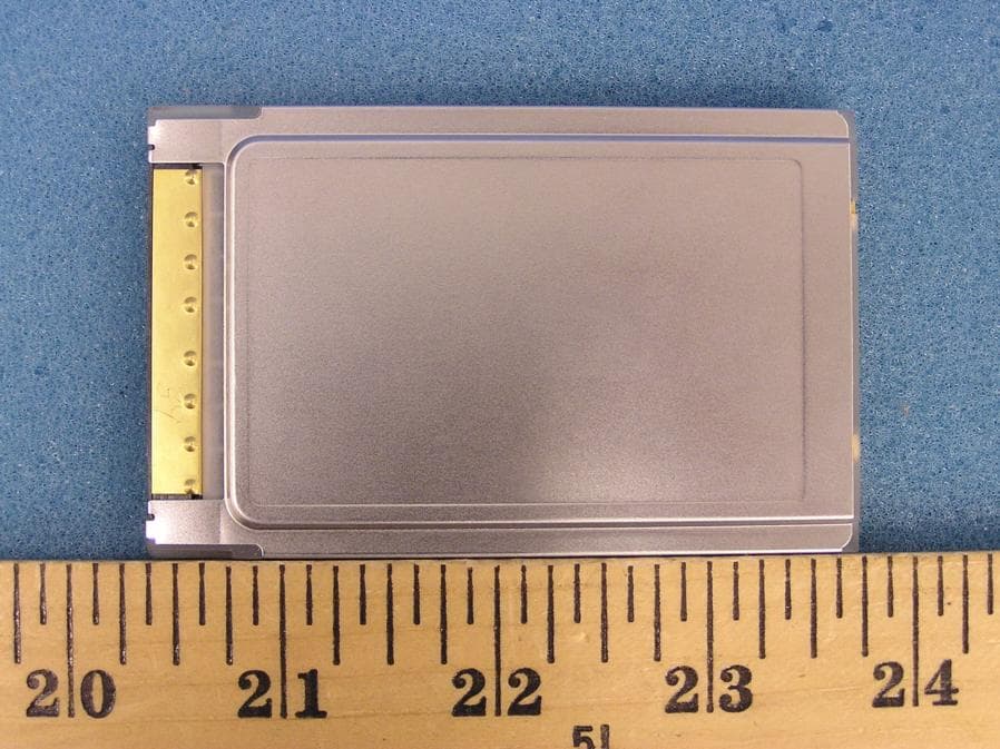
Click to zoom
Application Details
- Equipment Class
- DSS - Part 15 Spread Spectrum Transmitter
- Date of Grant
- May 11, 2005
- Application Purpose
- Original Equipment
- Date of Application
- May 11, 2005
- Equipment Note
- RFID Gun with WLAN
- Frequency Range
- 902.75000000 - 926.75000000
- Company
- Symbol Technologies Inc
- Country
- United States
Documents & Files
Document Text
Text extracted from the exhibit documents filed with the FCC. Open a document above to read the original.
Cover Letter(s)
Response to ATCB Comments FCC ID: HP9MC906RC 1 Washington Laboratories, Ltd. 7560 LINDBERGH DRIVE GAITHERSBURG, MD 20879 (301) 417 – 0220 FAX # (301) 417 - 9069 May 11, 2005 Mr. Tim Johnson American Telecommunications Certification Body Inc. 6731 Whittier Ave McLean, VA 22101 RE: Comments of May 10, 2005 APPLICATION: HP9MC906RC Symbol Technologies, Inc. Dear Mr. Johnson: Below are the comments that you have provided regarding the application for certification referenced above. Our responses to those comments are in bold italic. Many responses refer you to additional exhibit(s) which has been uploaded to the application folder at the ATCB website. Thank you for your attention. Please feel free to contact us for any additional information that you may require. Regards, Gregory M. Snyder Chief EMC Engineer, Wireless/Telco Services Manager Brian J. Dettling Documentation Specialist WLL Project: 8596/7 1) The Grantee code appear incorrect on the 731 form provided, please correct. R. The Grantee Code has been corrected. Please see exhibit “MC906RC Application Form - 731 rev2”. 2) The output power for 2412-2462 appears to list 114.8 mW for the 2.4 GHz TX. Additionally, the Washington Labs report and MPE also lists 114.8 mW. However, the test report for the 2.4 GHz appears to list 38 mW. Please review, explain and correct any affected exhibits. Note this may affect report results in the MPE/operational description as well. Response to ATCB Comments FCC ID: HP9MC906RC 2 R. The correct conducted output power for the 2416 – 2462MHz card is 38.5mW as indicated in the 2.4GHz test report. Please see exhibits “MC906RC Test Report Rev2.pdf”, “MC906RC RF Exposure Info Rev2.pdf”, and the revised Form 731, all of which have been changed to reflect the correct power. 3) For the internal photographs provided, a photograph of the bottom of the board (page 8 of 10) should be provided with the label and shield removed. Please provide. R. Please see exhibit “MC906RC Internal Photos Supplement.pdf”. 4) Please provide the users guide referenced in response item 21 that includes 15.21, 15.105, and RF exposure statements. R. Please see exhibit “MC906RC User Manual QRG Rev1.pdf”. Also, please note: in response to your email, the RSP100 form for Industry Canada has been revised. Please see exhibit “MC906RC Application Form - IC Rev1.pdf”.
Cover Letter(s)
Response to ATCB Comments FCC ID: HP9MC906RC 1 Washington Laboratories, Ltd. 7560 LINDBERGH DRIVE GAITHERSBURG, MD 20879 (301) 417 – 0220 FAX # (301) 417 - 9069 May 5, 2005 Mr. Tim Johnson American Telecommunications Certification Body Inc. 6731 Whittier Ave McLean, VA 22101 RE: Comments of May 3, 2005 APPLICATION: HP9MC906RC Symbol Technologies, Inc. Dear Mr. Johnson: Below are the comments that you have provided regarding the application for certification referenced above. Our responses to those comments are in bold italic. Many responses refer you to additional exhibit(s) which has been uploaded to the application folder at the ATCB website. Thank you for your attention. Please feel free to contact us for any additional information that you may require. Regards, Gregory M. Snyder Chief EMC Engineer, Wireless/Telco Services Manager Brian J. Dettling Documentation Specialist WLL Project: 8596/7 1) From review of this application and our conversations, it is my understanding that we are approving this device under its own FCC ID as a system and not relying on any modular approvals. Please confirm that our understanding is correct. R. This device is to be approved as a system under its’ own FCC ID. 2) Additionally, data from various reports from previous approvals have been provided. You have stated that there are not any changes to the approved radios. However, justify the use of this data and additionally please explain if there are any changes to the antennas or surrounding circuitry that would affect spurious emissions. Response to ATCB Comments FCC ID: HP9MC906RC 2 R. No changes to the approved radios has occurred except that the antenna used for the RFID radio has been changed. With the exception of the radiated emissions/co-location data the data from the existing radio testing is being used for this approval as nothing has changed. 3) FYI.....It would be suggested that for future applications of this kind, that a separate cover letter explaining the nature of the application be provided to help clarify all aspects of the application. I have attached 2 files as an example of this for your reference regarding a previous application of significant complexity. R. Noted. 4) The label mentions “This device contains Radio Approved Modules”. This is not appropriate labeling for the device as a module or system. However, assuming this is a system approval, this statement is not relevant and should be removed. R. The label has been modified to remove the irrelevant statement. Please see “MC906RC Label Location Rev 1.pdf”. 5) The 2 part FCC statement information appears to possibly be placed elsewhere on the device. Additionally, the labeling information references 2 other documents for more regulatory information. Please provide sample labels and information showing the location on the device of any other labels relevant to FCC or IC compliance. R. Due to limited space on the label and device the 2- part FCC statement is located in the Quick Reference Guide as indicated on the label. A significant amount of precedence has been set where the FCC has accepted these statements to be on the Quick Reference Guide for all previous versions of this same device. The remaining area on the device is reserved for other international marks that are specifically required to be on the product. 6) If this is being granted as a system, then the device is being approved for a combined device containing both TX’s (900 MHz DSS and an 2.4 GHz DTS device). This will be considered a composite application as 2 grants will need to be issued for the FCC. Please update the 731 form, section III – 4(a) to list both types of devices (DSS and DTS). Additionally, the equipment specifications for section III – 6(b) should report the RF power output for each TX separately. R. The form has been revised per the above. Please see exhibit “MC906RC Application Form - 731 revised.pdf”. 7) The block diagram appears to only have been provided for the 900 MHz portion of the device. Please provide the block diagram for the 2.4 GHz Radio as well. R. The block diagram for the 2.4GHz radio has been provided. Please see exhibit “MC906RC Block Diagram.pdf”. Please refer to page 4 of the Block Diagram. 8) Internal photographs do not appear to be provided showing the 2.4 GHz radio location, antenna, and top/bottom views as required by the FCC. Additionally, due to the integrated radio, and RF ID support board, internal photographs of all boards in within the device should be provided. Please note that generally, for unlicensed devices the FCC desires to see photographs of all boards as well. R. Additional internal photographs have been provided Please see exhibit “MC906RC Internal Photos Rev 1.pdf”. Response to ATCB Comments FCC ID: HP9MC906RC 3 9) Antenna specification information appears to be provided for the 900 MHz device. Please provided detailed specifications on the antennas for the 2.4 GHz? R. The revised internal photograph exhibit now contains the 1dBi gain dipole antenna used for the 2.4GHz. In addition, a spec sheet for the antenna has been provided. Please see exhibit “MC906RC Antenna info.pdf”. 10) The operational description states that the antenna gain is maximum -6 dBi (page 37 of 45). The additional antenna information given in the antenna specification sheet is + 6 dBi. The MPE exhibits appears to utilize a +6 dBi antenna gain in the calculations. What is correct? Please correct all affected exhibits. R. The operational description has revised to show the correct gain of +6dBi. Please see exhibit “MC906RC Operational Description Rev 1.pdf”. 11) The operational description mentions an integrated 2.4 GHz radio, but also mentions a non-radio version. The manufacturer should be aware that this device as approved will require the device to always contain both TX’s. Depopulation of the 2.4 gHz radio would not be allowed under the FCC ID of this application. R. Please see the revised operational description. 12) The operation…
Text truncated - open the document above for the full version.
Cover Letter(s)
One Symbol Plaza, Holtsville, NY 11742-1300 • 1.631.738.2400 • www.symbol.com MB/TCB/Confidentiality/H9PMC906RC Washington Laboratories, LTD. 7560 Lindbergh Drive, Gaithersburg, Maryland 20879 Confidentiality Request Pursuant to Sections 0.457(d)(1)(ii) and 0.459 of the Commission’s Rules, Symbol Technologies Inc. hereby requests confidential treatment of information accompanying as outlined below: • Schematics • Block Diagrams • Parts List (Bill of Materials) • Theory of Operation • Antenna Specifications The above materials contain trade secrets and proprietary information not customarily released to the public. The public disclosure of these matters might be harmful to the Applicant and provide unjustified benefits to its competitors. The Applicant understands that pursuant to Rule 0.457(d)(1)(ii), disclosure of this Application and all accompanying materials will not be made before the date of the Grant for this Application. Yours sincerely, Dennis Cortes Symbol Regulatory Compliance Direct Tel: (631) 738-5358 Email: [email protected] Regulatory Engineering • Web Site: http://ww.symbol.com
External Photos
External Photos
External Photos
WJ Communications Inc. 1.0 Watt RFID Reader External Photographs
ID Label/Location Info
PROD FAM: GEMINI, GUN DESCRIPTION: LBL:LCD,MC906R-G,US (MTM/WJ CLASS 0/1 RFID) CTRY CODE:US COUNTRY: US/CAN SN POOL: STANDARD LBL STOCK PN: 63-62650-01 SEE NOTE 2 LBL SCRIPT : 6642805X *SEE NOTE 1 CCG1:M119 NOTES: UNLESS OTHERWISE SPECIFIED 1. SCRIPT FILE TO BE CREATED BY MANUFACTURING. SCRIPT FILE MUST MATCH THIS DOCUMENT EXACTLY AND HAVE SAME REVISION. 2. LABEL STOCK P/N IS SUBJECT TO CHANGE. CHECK BOM FOR ACTUAL PART NUMBER. 3. IN ALL CASES "XXX......" REPRESENTS VARIABLE FIELDS IN SCRIPT FILE. ACTUAL NUMBER OF CHARACTERS IN SCRIPT FILE MAY VARY. 4. IN THE CASE OF MULTIPLE APPROVALS THE ID NUMBER AND TYPE NUMBERS APPEAR IN SAME ORDER. 5. PART NUMBER MAY OR MAY NOT HAVE DASH BEFORE COUNTRY CODE. SEE BOM FOR ACTUAL MODEL DESCRIPTION. 6. "MFD:" REPRESENTS MANUFACTURE DAY, MONTH, YEAR AND REVISION OF PART NUMBER(IE: 12SEP03 X) 7. COUNTRY OF ORIGIN REQUIRED 8. ADD VARIABLE FIELD FOR PLANT CODE EDR:74646 69-66428-05A SEE NOTE 6 SEE NOTE 5 SEE NOTE 7 AND 8 LASERLICHT - NICHT IN DEN STRAHL BLICKEN. LASER KLASSE 2 LUMIÈRE LASER -NE PAS REGARDER DANS LE FAISCEAU APPAREIL À LASER DE CLASSE 2. CAUTION-LASER LIGHT. DO NOT STARE INTO BEAM. CLASS 2 LASER PRODUCT 630-680 nM, 1 mW (S)S/N: XXXXXXXXXXXXXXX P/N: MC906R-GXXXXXXR5US MFD: XXXXXXX X SN BAR CODE MADE IN XXXXXXX XXXX FOR ADDITIONAL REGULATORY INFORMATION SEE: 60-62651-02 AND 60-63966-01 SEE QRG FOR PATENT AND RADIO INFORMATION SYMBOL TECHNOLOGIES INC. HOLTSVILLE, N.Y. 11742 TYPE: MC906R FCC ID: H9PMC906RC IC: 1549D-MC906RC 11-16V 2A Label Location
Internal Photos
Internal Photos
Internal Photos
WJ Communications Inc. 1.0 Watt RFID Reader Internal Photographs
RF Exposure Info
Document 8596-MPE, Rev. 2 FCC ID: H9PMC906RC RF Exposure Evaluation Washington Laboratories, Ltd May 2005 Maximum Permissible Exposure Evaluation for MC906R RFID Reader FCC ID: H9PMC906RC March 31, 2005 WLL PROJECT #: 8596 This report may not be reproduced, except in full, without the prior written consent of Washington Laboratories, Ltd. RF Exposure Evaluation Document 8596-MPE, Rev. 2 FCC ID: H9PMC906RC RF Exposure Evaluation Washington Laboratories, Ltd May 2005 1 Maximum Permissible Exposure Evaluation for FCC ID: H9PMC906RC 1.0 Introduction This report has been prepared on behalf of Symbol Technologies, Inc. Model: MC906R mobile computer transceiver to show compliance with the RF exposure requirements as defined in FCC §1.1307. The Symbol MC906R mobile computer contains an 802.11b WLAN card and an RFID reader operating at 902M – 928MHz. 1.1 Requirements Three different categories of transmitters are defined by the FCC in OET Bulletin 65. These categories are fixed installation, mobile, and portable and are defined as follows: Fixed Installations: fixed location means that the device, including its antenna, is physically secured at a permanent location and is not able to be easily moved to another location. Additionally, distance to humans from the antenna is maintained to at least 2 meters. Mobile Devices: a mobile device is defined as a transmitting device designed to be used in other than fixed locations and to be generally used in such a way that a separation distance of at least 20 centimeters is normally maintained between the transmitter's radiating structures and the body of the user or nearby persons. Transmitters designed to be used by consumers or workers that can be easily re-located, such as a wireless modem operating in a laptop computer, are considered mobile devices if they meet the 20 centimeter separation requirement. The FCC rules for evaluating mobile devices for RF compliance are found in 47 CFR §2.1091. Portable Devices: a portable device is defined as a transmitting device designed to be used so that the radiating structure(s) of the device is/are within 20 centimeters of the body of the user. Portable device requirements are found in Section 2.1093 of the FCC's Rules (47 CFR§2.1093). For this test report the Symbol MC906R mobile computer system with 6dBi antenna is classified as a “Mobile Device”. As this device is being approved as a mobile device the MPE will be evaluated at the 20cm test distance. Document 8596-MPE, Rev. 2 FCC ID: H9PMC906RC RF Exposure Evaluation Washington Laboratories, Ltd May 2005 2 The FCC also categorizes the use of the device as based upon the user’s awareness and ability to exercise control over his or her exposure. The two categories defined are Occupational/ Controlled Exposure and General Population/Uncontrolled Exposure. Since there are no warnings or training associated with this unit and it can be used by anyone, the Symbol MC906R mobile computer transceiver is evaluated to the General Population/Uncontrolled Exposure limits. The two limits applicable for the MC906R are as follows: RFID Device operating at 902M – 928MHz: 0.601mW/cm 2 WLAN Device operating at 2412M – 2462MHz: 1mW/cm 2 As a composite device, each transmitters Power Density is calculated and compared to its respective limit. The percentages of each level to its respective limit are then added together and the total percentage must be less than 100% to ensure compliance with the MPE limits. 1.2 Radio Frequency Radiation Exposure Evaluation The highest RF output power of the unit was measured at 38.5mW at 2462MHz. The highest RF power measured for the RFID unit is 29.8dBm (955mW) at 927.225MHz. According to §1.1310 of the FCC rules, the power density limit for General Population/Uncontrolled Exposure at 902.75MHz is 0.601mW/cm 2 . For the 802.11b card the limit is 1mW/cm 2 . As this is a mobile device the MPE shall be calculated at 20cm to show compliance with the power density limit. The following formula was used to calculate the minimum safe distance: 2 4R PG S π = Where: S = Power Density P = Output Power at the Antenna Terminals G = Gain of Transmit Antenna (linear gain) R = Distance from Transmitting Antenna 1. For the 802.11b card device, the calculation is as follows: R = 20cm P = Output Power = 38.5mW G = Worst Case Gain = 1dBi = INVLOG(1/10) = 1.26 )20( 4 )26.1()5.38( 2 ×× × = π S = 0.0097 mW/cm 2 (Based on continuous transmission) This represents a 0.97% in reference to the allowable limit of 1mW/cm 2 . Document 8596-MPE, Rev. 2 FCC ID: H9PMC906RC RF Exposure Evaluation Washington Laboratories, Ltd May 2005 3 2. For the RFID device, the calculation is as follows: R = 20cm P = Output Power = 995mW (Continuous transmission) Per the theory of operation the transmitter is limited to a duty cycle of 73% maximum. This results in a time averaging reduction of 1.25dB or: P 75%DC = 995 x 0.73 = 726.4mW G = Worst Case Gain = 6dBi = INVLOG(6/10) = 4 )20( 4 )4()4.726( 2 ×× × = π S = 0.578 mW/cm 2 (Based on 75% Operation) This represents a 96.2% in reference to the allowable limit of 0.601mW/cm 2 . Adding the total percentages together gives a 97.2% of the total allowable MPE. Thus the MC906R complies with the MPE requirements at 20cm for a mobile unit with co-located devices. Document 8596-MPE, Rev. 2 FCC ID: H9PMC906RC RF Exposure Evaluation Washington Laboratories, Ltd May 2005 4 Figure 1. Separation Distance to Antenna
Test Report
Document 8596/7-01, Rev. 2 FCC ID: H9PMC906RC IC ID : 1549D-MC906RC FCC & IC Certification Test Report Washington Laboratories, Ltd May 2005 Certification Test Report for Symbol Technologies, Inc. MC906R Mobile Computer with RFID Reader and 802.11b Device FCC ID: H9PMC906RC IC ID: 1549D-MC906RC April 26, 2005 Rev. 1: May 5, 2005 Rev, 2: May 11, 2005 Prepared for: Symbol Technologies, Inc. One Symbol Plaza M/S B-4 Holtsville, NY 11742 Prepared By: Washington Laboratories, Ltd. 7560 Lindbergh Drive Gaithersburg, Maryland 20879 Certification Test Report Document 8596/7-01, Rev. 2 FCC ID: H9PMC906RC IC ID : 1549D-MC906RC FCC & IC Certification Test Report Washington Laboratories, Ltd May 2005 Certification Test Report for the Symbol Technologies, Inc. MC906R Mobile Computer with RFID Reader and 802.11b Device FCC ID: H9PMC906RC IC ID: 1549D-MC906RC April 26, 2005 WLL JOB# 8596/7 Prepared by: Gregory M. Snyder Chief EMC Engineer Reviewed by: Steven D. Koster EMC Operations Manager Document 8596/7-01, Rev. 2 FCC ID: H9PMC906RC IC ID : 1549D-MC906RC FCC & IC Certification Test Report Washington Laboratories, Ltd May 2005 ii Abstract This report has been prepared on behalf of Symbol Technologies, Inc. to support the attached Application for Equipment Authorization. The test report and application are submitted for a Frequency Hopping Spread Spectrum Transmitter under Part 15.247 of the FCC Rules and Industry Canada RSS-210, and an 802.11b radio. The MC906RC contains 2 previously approved radios. The 802.11 card is approved as a module under FCC ID: H9P2164436 and the RFID radio is approved under FCC ID: NTTWJMPR7XXX. Additionally the 802.11 card is approved with a system under FCC ID: H9PMC906RA. The MC906RC in this report is identical to the H9PMC906RA except that the RFID radio has been replaced with a WJ reader FCC ID: NTTWJMPR7XXX. This Certification Test Report documents the test configuration and test results for the MC906RC. As both radios can operate simultaneously and are considered co-located, testing for spurious radiated emissions was performed with both radios transmitting. Since there are no changes to the approved radios the existing test reports are used for compliance. Testing was performed on an Open Area Test Site (OATS) of Washington Laboratories, Ltd, 7560 Lindbergh Drive, Gaithersburg, MD 20879. Site description and site attenuation data have been placed on file with the FCC's Sampling and Measurements Branch at the FCC laboratory in Columbia, MD. Washington Laboratories, Ltd. has been accepted by the FCC and approved by NIST NVLAP (NVLAP Lab Code: 200066-0) as an independent FCC test laboratory. The MC906RC complies with the limits of §15.247 and RSS-210. Revision 1 of this test report includes bandedge data for the 802.11b radio operating on Channel 1 and Channel 11. Revision 2 of this test report updates Table 1 to list the correct conducted power of 38.5mW. Document 8596/7-01, Rev. 2 FCC ID: H9PMC906RC IC ID : 1549D-MC906RC FCC & IC Certification Test Report Washington Laboratories, Ltd May 2005 iii Table of Contents Abstract ............................................................................................................................... ii 1 Introduction..............................................................................................................1 1.1 Compliance Statement .........................................................................................1 1.2 Test Scope ............................................................................................................1 1.3 Contract Information............................................................................................1 1.4 Test and Support Personnel .................................................................................1 2 Equipment Under Test .............................................................................................2 2.1 EUT Identification & Description .......................................................................2 2.2 Test Configuration and Conditions......................................................................3 2.3 Test Location .......................................................................................................3 2.4 Measurements ......................................................................................................3 2.4.1 References........................................................................................................3 2.5 Measurement Uncertainty....................................................................................3 3 Test Equipment ........................................................................................................4 4 Test Results ..............................................................................................................5 4.1 Radiated Spurious Emissions, Co-location..........................................................5 4.1.1 Test Procedure...............................................................................................5 List of Tables Table 1. Device Summary................................................................................................... 2 Table 2: Test Equipment List.............................................................................................. 4 Table 3: Radiated Emission Test Data................................................................................ 7 Table 4, Bandedge Radiated Emissions Test Data ........................................................... 14 Table 5, Bandedge Radiated Emissions Test Data ........................................................... 16 Document 8596/7-01, Rev. 2 FCC ID: H9PMC906RC IC ID : 1549D-MC906RC FCC & IC Certification Test Report Washington Laboratories, Ltd May 2005 Page 1 of 17 1 Introduction 1.1 Compliance Statement The MC906RC complies with the limits for a Frequency Hopping Spread Spectrum Transmit…
Text truncated - open the document above for the full version.
Test Report
FCC CFR47 PART 15 SUBPART C CERTIFICATION TEST REPORT FOR PCMCIA RFID READER CARD MODEL NUMBER: MPR7000 FCC ID: NTTWJMPR7XXX REPORT NUMBER: 04U2954-1 ISSUE DATE: NOVEMBER 22, 2004 Prepared for WJ COMUNICATIONS 401 RIVER OAKS PARKWAY SAN JOSE, CA 95134 Prepared by COMPLIANCE CERTIFICATION SERVICES 561F MONTEREY ROAD, MORGAN HILL, CA 95037, USA TEL: (408) 463-0885 FAX: (408) 463-0888 REPORT NO: 04U2954-1 DATE: NOVEMBER 22, 2004 EUT: ONE WATT PCMCIA RFID READER CARD: MPR7000 FCC ID: NTTWJMPR7XXX Page 2 of 89 COMPLIANCE CERTIFICATION SERVICES DOCUMENT NO: CCSUP4031A 561F MONTEREY ROAD, MORGAN HILL, CA 95037 USA TEL: (408) 463-0885 FAX: (408) 463-0888 This report shall not be reproduced except in full, without the written approval of CCS. Revision History Rev. Revisions Revised By REPORT NO: 04U2954-1 DATE: NOVEMBER 22, 2004 EUT: ONE WATT PCMCIA RFID READER CARD: MPR7000 FCC ID: NTTWJMPR7XXX Page 3 of 89 COMPLIANCE CERTIFICATION SERVICES DOCUMENT NO: CCSUP4031A 561F MONTEREY ROAD, MORGAN HILL, CA 95037 USA TEL: (408) 463-0885 FAX: (408) 463-0888 This report shall not be reproduced except in full, without the written approval of CCS. TABLE OF CONTENTS 1. ATTESTATION OF TEST RESULTS............................................................................................. 5 2. TEST METHODOLOGY.................................................................................................................. 6 3. FACILITIES AND ACCREDITATION.......................................................................................... 6 4. CALIBRATION AND UNCERTAINTY.......................................................................................... 6 4.1. MEASURING INSTRUMENT CALIBRATION............................................................................. 6 4.2. MEASUREMENT UNCERTAINTY............................................................................................... 6 5. EQUIPMENT UNDER TEST............................................................................................................7 5.1. DESCRIPTION OF EUT..............................................................................................................7 5.2. MAXIMUM OUTPUT POWER.................................................................................................... 7 5.3. DESCRIPTION OF AVAILABLE ANTENNAS............................................................................. 7 5.4. SOFTWARE AND FIRMWARE.................................................................................................... 8 5.5. WORST-CASE CONFIGURATION AND MODE......................................................................... 8 5.6. DESCRIPTION OF TEST SETUP................................................................................................ 9 6. TEST AND MEASUREMENT EQUIPMENT.............................................................................. 11 7. LIMITS AND RESULTS................................................................................................................. 12 7.1. ANTENNA PORT CHANNEL TESTS FOR CLASS 0 MODULATION..................................... 12 7.1.1. 20 dB BANDWIDTH......................................................................................................... 12 7.1.2. HOPPING FREQUENCY SEPARATION......................................................................... 16 7.1.3. NUMBER OF HOPPING CHANNELS............................................................................. 18 7.1.4. AVERAGE TIME OF OCCUPANCY............................................................................... 20 7.1.5. PEAK OUTPUT POWER.................................................................................................. 24 7.1.6. MAXIMUM PERMISSIBLE EXPOSURE........................................................................ 28 7.1.7. CONDUCTED SPURIOUS EMISSIONS.......................................................................... 31 7.2. ANTENNA PORT CHANNEL TESTS FOR CLASS 1 MODULATION..................................... 40 7.2.1. 20 dB BANDWIDTH......................................................................................................... 40 7.2.2. HOPPING FREQUENCY SEPARATION......................................................................... 44 7.2.3. NUMBER OF HOPPING CHANNELS............................................................................. 46 7.2.4. AVERAGE TIME OF OCCUPANCY............................................................................... 48 7.2.5. PEAK OUTPUT POWER.................................................................................................. 52 7.2.6. MAXIMUM PERMISSIBLE EXPOSURE........................................................................ 56 7.2.7. CONDUCTED SPURIOUS EMISSIONS.......................................................................... 59 7.3. RADIATED EMISSIONS.............................................................................................................68 7.3.1. TRANSMITTER RADIATED SPURIOUS EMISSIONS................................................. 68 7.3.2. TRANSMITTER RADIATED EMISSIONS ABOVE 1 GHZ WITH CLASS 0 MODULATION ................................................................................................................................. 71 REPORT NO: 04U2954-1 DATE: NOVEMBER 22, 2004 EUT: ONE WATT PCMCIA RFID READER CARD: MPR7000 FCC ID: NTTWJMPR7XXX Page 4 of 89 COMPLIANCE CERTIFICATION SERVICES DOCUMENT NO: CCSUP4031A 561F MONTEREY ROAD, MORGAN HILL, CA 95037 USA TEL: (408) 463-0885 FAX: (408) 463-0888 This report shall not be reproduced except in full, without the written approval of CCS. 7.3.3. TRANSMITTER RADIATED EMISSIONS ABOVE 1 GHZ WITH CLASS 1 MODULATION ................................................................................................................................. 72 1. WORST-CASE RADIATED EMISSIONS BELOW 1 GHz..................................................... 73 7.4…
Text truncated - open the document above for the full version.
Contact Information
Applicant
Qianlin Zhou(Regulatory Specialist)
Technical Contact
Washington Laboratories, Ltd.Gregory M Snyder
[email protected]301-417-0220
7560 Lindbergh Drive · Gaithersburg, Maryland · United States
Non-Technical Contact
Washington Laboratories, Ltd.Brian J Dettling
[email protected]301-417-0220
Test Firm
Washington Laboratories, Ltd.Michael Violette
Technical Specifications
| # | Rule Parts | Frequency Range | Power Output |
|---|---|---|---|
| 1 | 15C | 902.75 MHz - 926.75 MHz | 955.00 mW |
Other Applications from Symbol Technologies Inc

H9PCCHUB1
Jun 30, 2015Customer Concierge
Equipment Class
NII - Unlicensed National Information Infrastructure TX
H9PAP7562
May 10, 2015802.11 abgn/ac Access Point
Equipment Class
DTS - Digital Transmission System
H9PTC75AH
Mar 26, 2015Touch Computer
Equipment Class
NII - Unlicensed National Information Infrastructure TX
H9PRA1202
Sep 24, 2014UHF Narrowband Radio Module
Equipment Class
TNB - Licensed Non-Broadcast Station Transmitter
H9PEMG101
Aug 26, 2014802.15.4 Gateway
Equipment Class
DTS - Digital Transmission System