H9PMR400MR400 RFID Reader Module
Symbol Technologies Inc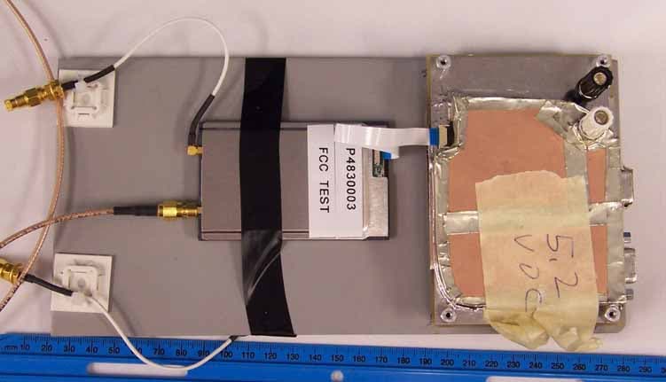
Click to zoom
Application Details
- Equipment Class
- DSS - Part 15 Spread Spectrum Transmitter
- Date of Grant
- Oct 16, 2006
- Application Purpose
- Original Equipment
- Date of Application
- Oct 16, 2006
- Equipment Note
- MR400 RFID Reader Module
- Frequency Range
- 902.75000000 - 927.25000000
- Company
- Symbol Technologies Inc
- Country
- United States
Documents & Files
Document Text
Text extracted from the exhibit documents filed with the FCC. Open a document above to read the original.
Users Manual
MR400 RFID Reader Module Integration Guide MR400 RFID Reader Module, Integration Guide 72E-89971-01 Revision 1 October 2006 © 2006 by Symbol Technologies, Inc. All rights reserved. No part of this publication may be reproduced or used in any form, or by any electrical or mechanical means, without permission in writing from Symbol. This includes electronic or mechanical means, such as photocopying, recording, or information storage and retrieval systems. The material in this manual is subject to change without notice. The software is provided strictly on an “as is” basis. All software, including firmware, furnished to the user is on a licensed basis. Symbol grants to the user a non-transferable and non-exclusive license to use each software or firmware program delivered hereunder (licensed program). Except as noted below, such license may not be assigned, sublicensed, or otherwise transferred by the user without prior written consent of Symbol. No right to copy a licensed program in whole or in part is granted, except as permitted under copyright law. The user shall not modify, merge, or incorporate any form or portion of a licensed program with other program material, create a derivative work from a licensed program, or use a licensed program in a network without written permission from Symbol. The user agrees to maintain Symbol’s copyright notice on the licensed programs delivered hereunder, and to include the same on any authorized copies it makes, in whole or in part. The user agrees not to decompile, disassemble, decode, or reverse engineer any licensed program delivered to the user or any portion thereof. Symbol reserves the right to make changes to any software or product to improve reliability, function, or design. Symbol does not assume any product liability arising out of, or in connection with, the application or use of any product, circuit, or application described herein. No license is granted, either expressly or by implication, estoppel, or otherwise under any Symbol Technologies, Inc., intellectual property rights. An implied license only exists for equipment, circuits, and subsystems contained in Symbol products. Symbol, MR400, Spectrum One, and Spectrum24 are registered trademarks of Symbol Technologies, Inc. Bluetooth is a registered trademark of Bluetooth SIG. Microsoft, Windows and ActiveSync are either registered trademarks or trademarks of Microsoft Corporation. Other product names mentioned in this manual may be trademarks or registered trademarks of their respective companies and are hereby acknowledged. Symbol Technologies, Inc. One Symbol Plaza Holtsville, New York 11742-1300 http://www.symbol.com Patents This product is covered by one or more of the patents listed on the web site: www.symbol.com/patents Revision History Changes to the original manual are listed below: ChangeDateDescription -01 Rev 110/2006BETA Table of Contents Chapter 1 Table of Contents Revision History ............................................................................................................. iii Table of Contents About This Guide Introduction .................................................................................................................... i Documentation Set .................................................................................................. i Configurations................................................................................................................ i Chapter Descriptions ..................................................................................................... i Notational Conventions.................................................................................................. ii Notes, Cautions and Warnings ................................................................................ ii Related Documents ....................................................................................................... iii Service Information ........................................................................................................ iii Chapter 1: Introduction Overview ....................................................................................................................... 1-1 Theory of Operation ...................................................................................................... 1-2 Block Diagram ......................................................................................................... 1-2 Controller ........................................................................................................... 1-2 Baseband Processor ......................................................................................... 1-3 Transceiver ....................................................................................................... 1-3 External Hardware Interfaces ....................................................................................... 1-3 Input Voltage ........................................................................................................... 1-3 Antenna Interface .................................................................................................... 1-3 Host Interface .......................................................................................................... 1-4 Mechanical Characteristics ........................................................................................... 1-5 Dimensions ............................................................................................................. 1-5 Weight ..................................................................................................................... 1-5 Enclosure and EMI Shielding .................................................................................. 1-5 Environmental Characteristics ...................................................................................... 1-6 Thermal Management ..........…
Text truncated - open the document above for the full version.
Cover Letter(s)
One Symbol Plaza, Holtsville, NY 11742-1300 • 1.631.738.2400 • www.symbol.com Confidentiality Request: Symbol Technologies June 16th 2006 Federal Communications Commission Authorization and Evaluation Division FCC ID: H9PMR400 Pursuant to Sections 0.457 and 0.459 of the Commission’s Rules, the Applicant hereby requests confidential treatment of information accompanying this Application as outlined below: • Bill of Materials • Block Diagram • Schematics • Theory of Operation The above materials contain trade secrets and proprietary information not customarily released to the public. The public disclosure of these matters might be harmful to the Applicant and provide unjustified benefits to its competitors. The Applicant understands that pursuant to Rule 0.457, disclosure of this Application and all accompanying documentation will not be made before the date of the Grant for this application Sincerely yours, For: Mark Luksich Director, Regulatory Symbol Technologies Inc. 1 Symbol Plaza Holtsville, NY 11742
Cover Letter(s)
American Telecommunications Certification Body Inc. 6731 Whittier Ave, McLean, VA 22101 September 27, 2006 RE: FCC ID: H9PMR400_ATCB004061 Attention: Greg Snyder I have a few comments on this Application. Please note that further comments may arise in response to answers provided to the questions below. 1. Please note that the rf exposure calculations were performed assuming a frequency of 902.75MHz, a power level of 28.45dBm and a gain of 6dBi. However, the test report states that the power measured at 902.75MHz is 29.75dBm and not 28.45dBm. This means that at 902.75MHz the rf exposure calculation at that frequency and power setting would be 22.16cm. The manual states a minimum 23cm separation is needed. Please correct the MPE report to reflect actual power and frequencies used (i.e. please use the minimum 23cm mentioned in the manual). 2. Please note that page 8 and 17 of the test report states the frequency range of the device is 902.75M – 927.25MHz. Please note that the test data on page 14 of the report states the high frequency is 907.75MHz. Please explain and please correct as necessary. 3. FYI – please note that the data tables should clearly identify average vs peak readings. While the limits for average and peak are listed and while the procedure section states that peak and average data is listed, the data table does not declare or clearly indicate what data is for which limit. Please consider clearly identifying average data and peak data. 4. Please note that the non modification statement on page 41 of the manual says, “Any changes or modifications not expressly approved by <OEM>, could void the user's authority to operate the equipment.” Please note that this does not appear to meet the requirements of 15.21 as the term <OEM> is not clarified nor identified to be the grantee or party responsible for compliance. Please also note that page 36 of the manual repeats the statement but uses Symbol in place of the <OEM>. Please explain and please correct as necessary. 5. Please note that the test report states that the type antenna used during testing is a 6dBi “Panel” antenna. Please note that page 38 of the manual states that the approved antenna is a “Circular polarized” antenna (model AN480). Please note that “panel” type antennae, unless specifically designed with antenna array segments in both horizontal and vertical polarization, are not necessarily considered to have a circular polarization (i.e. radiating both horizontal and vertical polarized patterns). Please explain the relationship between the panel type antenna listed in the report and the circular polarized antenna specified in the manual. 6. Please note that page 40 of the manual clearly states that the device is approved for “mobile” only configurations. Please note that the manual on pages 41 states handheld use and then page 40 states that use is restricted to mobile only. Please explain and please justify how this device with the antenna specified 9circular polarized) can be used in a hand held operation and please include information on how the 23 cm separation is met under a condition of hand held operation. 7. Please provide the list of hopping frequencies and how they are pseudo-random. Dennis Ward mailto:[email protected] The items indicated above must be submitted before processing can continue on the above referenced application. Failure to provide the requested information may result in application termination. Correspondence should be considered part of the permanent submission and may be viewed from the Internet after a Grant of Equipment Authorization is issued. z Page 2 September 27, 2006 Please do not respond to this correspondence using the email reply button. In order for your response to be processed expeditiously, you must submit your documents through the AmericanTCB.com website. Also, please note that partial responses increase processing time and should not be submitted. Any questions about the content of this correspondence should be directed to the sender.
Cover Letter(s)
Response to ATCB Comments FCC ID: H9PMR400 1 Washington Laboratories, Ltd. 7560 LINDBERGH DRIVE GAITHERSBURG, MD 20879 (301) 417 – 0220 FAX # (301) 417 - 9069 October 10, 2006 Mr. Dennis Ward American Telecommunications Certification Body Inc. 6731 Whittier Ave McLean, VA 22101 RE: Comments of September 27, 2006 APPLICATION: H9PMR400 Symbol Technologies, Inc. Dear Mr. Ward: Below are the comments that you have provided regarding the application for certification referenced above. Our responses to those comments are in bold italic. Many responses refer you to additional exhibit(s) which has been uploaded to the application folder at the ATCB website. Thank you for your attention. Please feel free to contact us for any additional information that you may require. Regards, Gregory M. Snyder Chief EMC Engineer, Wireless/Telco Services Manager Brian J. Dettling Documentation Specialist WLL Project: 9284 1) Please note that the rf exposure calculations were performed assuming a frequency of 902.75MHz, a power level of 28.45dBm and a gain of 6dBi. However, the test report states that the power measured at 902.75MHz is 29.75dBm and not 28.45dBm. This means that at 902.75MHz the rf exposure calculation at that frequency and power setting would be 22.16cm. The manual states a minimum 23cm separation is needed. Please correct the MPE report to reflect actual power and frequencies used (i.e. please use the minimum 23cm mentioned in the manual). R. The output power reported in the MPE document is 29.75dBm but is then reduced to 28.45dBm based on operational duty cycle. This level was then used for calculating the Power Density at 20cm. 2) Please note that page 8 and 17 of the test report states the frequency range of the device is 902.75M – 927.25MHz. Please note that the test data on page 14 of the report states the high frequency is 907.75MHz. Please explain and please correct as necessary. Response to ATCB Comments FCC ID: H9PMR400 2 R. The table has been corrected to show the correct frequency of 927.25MHz. Please see”MR400 Test Report – revised”. 3) FYI – please note that the data tables should clearly identify average vs peak readings. While the limits for average and peak are listed and while the procedure section states that peak and average data is listed, the data table does not declare or clearly indicate what data is for which limit. Please consider clearly identifying average data and peak data. R. Noted. The revised report has been updated to indicate the peak and average measurements. 4) Please note that the non modification statement on page 41 of the manual says, “Any changes or modifications not expressly approved by <OEM>, could void the user's authority to operate the equipment.” Please note that this does not appear to meet the requirements of 15.21 as the term <OEM> is not clarified nor identified to be the grantee or party responsible for compliance. Please also note that page 36 of the manual repeats the statement but uses Symbol in place of the <OEM>. Please explain and please correct as necessary. R. The requirements have been addressed in the corrected manual. Please see “MR400 User Manual – revised”. 5) Please note that the test report states that the type antenna used during testing is a 6dBi “Panel” antenna. Please note that page 38 of the manual states that the approved antenna is a “Circular polarized” antenna (model AN480). Please note that “panel” type antennae, unless specifically designed with antenna array segments in both horizontal and vertical polarization, are not necessarily considered to have a circular polarization (i.e. radiating both horizontal and vertical polarized patterns). Please explain the relationship between the panel type antenna listed in the report and the circular polarized antenna specified in the manual. R. The antenna was inadvertently referred to as a “panel”. That designation has been removed from the revised report. Additionally, the connector type has been corrected. 6) Please note that page 40 of the manual clearly states that the device is approved for “mobile” only configurations. Please note that the manual on pages 41 states handheld use and then page 40 states that use is restricted to mobile only. Please explain and please justify how this device with the antenna specified 9circular polarized) can be used in a hand held operation and please include information on how the 23 cm separation is met under a condition of hand held operation. R. – 1) The Antenna used was a Reference Antenna for test purposes. 2) See page B–4of the User Manual for clear information on Final Product Compliance. 7) Please provide the list of hopping frequencies and how they are pseudo-random. R. Please see “MR400 Operational Description - Freq Hop”.
External Photos
External Photos ©2006 Washington Laboratories, Ltd Test Fixture External Photos ©2006 Washington Laboratories, Ltd
ID Label/Location Info
PROD FAM: MR400 DESCRIPTION: LBL:LCD, MR400 (VISUAL AID ONLY) CTRY CODE: US COUNTRY: US/CANADA SN POOL: STANDARD LBL STOCK PN: NA LBL SCRIPT : NA CCG1: F532 NOTES: UNLESS OTHERWISE SPECIFIED 1. SCRIPT FILE TO BE CREATED BY MANUFACTURING. SCRIPT FILE MUST MATCH THIS DOCUMENT EXACTLY AND HAVE SAME REVISION SEE STI LABEL SPEC P/N SP-10083-01 FOR GUIDANCE AND REQUIREMENTS. 2. LABEL STOCK TO BE SUPPLIED BY MANUFACTURING : SEE STI LABEL SPEC P/N SP-10083-01(MFG) FOR MATERIAL, CARRIER INFORMATION, AND ROLL OUT POSITION. 3. IN ALL CASES "XXX......" REPRESENTS VARIABLE FIELDS IN SCRIPT FILE. ACTUAL NUMBER OF CHARACTERS IN SCRIPT FILE MAY V ARY. 4. SERIAL NUMBER MUST BE 4PT MINIMUM CHARACTER HEIGHT IN SCRIPT FILE. 5. PART NUMBER MAY OR MAY NOT HAVE DASH BEFORE COUNTRY CODE. SEE BOM FOR ACTUAL MODEL DESCRIPTION. 6. "MFD:" REPRESENTS MANUFACTURE DAY, MONTH, YEAR AND REVISION OF PART NUMBER(IE: 12SEP03 X) 7. COUNTRY OF ORIGIN REQUIRED 8. ADD VARIABLE FIELD FOR PLANT CODE 9. LEAVE SPACE FOR FUTURE VARIABLE FIELD 69-88010-01. 1 P P D: 87496 SEE NOTE 4 SEE NOTE 5 SEE NOTE 7 SEE NOTE 8 SEE NOTE 9 FCC ID: H9PMR400 IC: 1549D-MR400 (S)SN: XXXXXXXXXXXXXX SYMBOL TECHNOLOGIES INC., HOLTSVILLE N.Y. MADE IN XXXXXXXX XXXX S N B A R C O DE MODEL: MR400 XXXXXXXXXXXXXXXXXXXXXXXXX XX V --- XXXA THIS DEVICE COMPLIES WITH PART 15 OF THE FCC RULES. OPERATION IS SUBJECT TO THE FOLLOWING TWO CONDITIONS:(1) THIS DEVICE MAY NOT CAUSE HARMFUL INTERFERENCE AND (2) THIS DEVICE MUST ACCEPT ANY INTERFERENCE RECEIVED INCLUDING INTERFERENCE THAT MAY CAUSE UNDESIRED OPERATION. THIS CLASS B DIGITAL APPARATUS COMPLIES WITH CANADIAN ICES-003. CET APPAREIL NUMÉRIQUE DE LA CLASSE B EST CONFORME À LA NORME NMB-003 DU CANADA. SEE PRODUCT GUIDE FOR RADIO AND PATENT INFO. MR400XXXXX LABEL SIZE: 2.55 X1.60 X .05R (4 PL) PRELIMINARY 7/10/06 ????? Label Location
Internal Photos
Internal Photos ©2006 Washington Laboratories, Ltd Internal Photos ©2006 Washington Laboratories, Ltd
RF Exposure Info
Document SYM9284-MPE FCC ID: H9PMR400 RF Exposure Test Report Washington Laboratories, Ltd September 2006 Maximum Permissible Exposure Evaluation for Symbol Technologies, Inc. MR400 FCC ID: H9PMR400 IC: 1549D-MR400 September 22, 2006 WLL PROJECT #: 9284 This report may not be reproduced, except in full, without the prior written consent of Washington Laboratories, Ltd. RF Exposure Evaluation Document SYM9284-MPE FCC ID: H9PMR400 RF Exposure Test Report Washington Laboratories, Ltd September 2006 1 Maximum Permissible Exposure Test Report for FCC ID: H9PMR400 IC: 1549D-MR400 1.0 Introduction This report has been prepared on behalf of SYMBOL TECHNOLOGIES, INC. MR400 transmitter to show compliance with the RF exposure requirements as defined in FCC §1.1307. 1.1 Requirements Three different categories of transmitters are defined by the FCC in OET Bulletin 65. These categories are fixed installation, mobile, and portable and are defined as follows: Fixed Installations: fixed location means that the device, including its antenna, is physically secured at a permanent location and is not able to be easily moved to another location. Additionally, distance to humans from the antenna is maintained to at least 2 meters. Mobile Devices: a mobile device is defined as a transmitting device designed to be used in other than fixed locations and to be generally used in such a way that a separation distance of at least 20 centimeters is normally maintained between the transmitter's radiating structures and the body of the user or nearby persons. Transmitters designed to be used by consumers or workers that can be easily re-located, such as a wireless modem operating in a laptop computer, are considered mobile devices if they meet the 20 centimeter separation requirement. The FCC rules for evaluating mobile devices for RF compliance are found in 47 CFR §2.1091. Portable Devices: a portable device is defined as a transmitting device designed to be used so that the radiating structure(s) of the device is/are within 20 centimeters of the body of the user. Portable device requirements are found in Section 2.1093 of the FCC's Rules (47 CFR§2.1093). The FCC also categorizes the use of the device as based upon the user’s awareness and ability to exercise control over his or her exposure. The two categories defined are Occupational/ Controlled Exposure and General Population/Uncontrolled Exposure. These two categories are defined as follows: Document SYM9284-MPE FCC ID: H9PMR400 RF Exposure Test Report Washington Laboratories, Ltd September 2006 2 Occupational/Controlled Exposure: In general, occupational/controlled exposure limits are applicable to situations in which persons are exposed as a consequence of their employment, who have been made fully aware of the potential for exposure and can exercise control over their exposure. This exposure category is also applicable when the exposure is of a transient nature due to incidental passage through a location where the exposure levels may be higher than the general population/uncontrolled limits, but the exposed person is fully aware of the potential for exposure and can exercise control over his or her exposure by leaving the area or by some other appropriate means. Awareness of the potential for RF exposure in a workplace or similar environment can be provided through specific training as part of a RF safety program. If appropriate, warning signs and labels can also be used to establish such awareness by providing prominent information on the risk of potential exposure and instructions on methods to minimize such exposure risks. General Population/Uncontrolled Exposure: The general population / uncontrolled exposure limits are applicable to situations in which the general public may be exposed or in which persons who are exposed as a consequence of their employment may not be made fully aware of the potential for exposure or cannot exercise control over their exposure. Members of the general public would come under this category when exposure is not employment-related; for example, in the case of a wireless transmitter that exposes persons in its vicinity. Warning labels placed on low-power consumer devices such as cellular telephones are not considered sufficient to allow the device to be considered under the occupational/controlled category, and the general population/uncontrolled exposure limits apply to these devices. The Symbol Technology, Inc. MR400 is evaluated to the General Population/Uncontrolled Exposure limits. Evaluation is done as a mobile device. The MR400 is not to be body worn or have no intent of body worn accessories. 1.2 Radio Frequency Radiation Exposure Evaluation The MPE shall be calculated to show compliance with the power density limit for each radio and frequency individually at the minimum mounting distance. The total percentage of allowable RF Exposure will be calculated for each radio and then added to ensure the overall percentage does not exceed 100%. The following formula was used to calculate the Power Density fro each radio: 2 4R PG S π = Where: S = Power Density P = Output Power at the Antenna Terminals Document SYM9284-MPE FCC ID: H9PMR400 RF Exposure Test Report Washington Laboratories, Ltd September 2006 3 G = Gain of Transmit Antenna (linear gain) R = Distance from Transmitting Antenna Transmitter Data: Transmitter Frequency Power Output dBm Maximum Antenna Gain dB 902.75 MHz 29.7 6 The following table is the RF exposure calculation for the MR400. Document SYM9284-MPE FCC ID: H9PMR400 RF Exposure Test Report Washington Laboratories, Ltd September 2006 4 RFID Radio: Tra nsmitte r #1 Frequency 902.75 MHz Limit 0.602 mW/cm^2 Dista nce (cm), R = 20 cm Pow er (dBm), P = 28.45 dBm699.84 mW TX Ant Gain (dB), G = 6dB Pow er De nsity (S) = 0.554 mW/cm^2(at 20cm) Minimum Distance = 19.2 cm Note: The RFID transmitter power was reduced from 29.7dBm to 28.45dBm based on a 75% on- time duty cycle. (30ms x 50 freq.)/2sec = 0.75 Fr…
Text truncated - open the document above for the full version.
Test Report
FCC & Industry Canada Certification Test Report For the Symbol Technologies, Inc. MR400 FCC ID: H9PMR400 IC ID: 1549D-MR400 WLL JOB# 9284 September 22, 2006 Prepared for: Symbol Technologies, Inc. One Symbol Plaza Holtsville, NY 11742 Prepared By: Washington Laboratories, Ltd. 7560 Lindbergh Drive Gaithersburg, Maryland 20879 Symbol Technologies, Inc. MR400 FCC Certification Test Report September 2006 FCC & Industry Canada Certification Test Report for the Symbol Technologies, Inc. MR400 FCC ID: H9PMR400 IC ID: 1549D-MR400 September 22, 2006 WLL JOB# 9284 Prepared by: Brian J. Dettling Documentation Specialist Reviewed by: Michael F. Violette, P.E. President Symbol Technologies, Inc. MR400 FCC Certification Test Report September 2006 WLL Report #9284-01 - ii - © 2006 Washington Laboratories, Ltd. Abstract This report has been prepared on behalf of Symbol Technologies, Inc. to support the attached Application for Equipment Authorization. The test report and application are submitted for a Frequency Hopping Spread Spectrum Transmitter under Part 15.247 of the FCC Rules and Regulations and Spectrum Management and Telecommunications Policy RSS-210 of Industry Canada.. This Certification Test Report documents the test configuration and test results for a Symbol Technologies, Inc. MR400. Testing was performed on an Open Area Test Site (OATS) of Washington Laboratories, Ltd, 7560 Lindbergh Drive, Gaithersburg, MD 20879. Site description and site attenuation data have been placed on file with the FCC's Sampling and Measurements Branch at the FCC laboratory in Columbia, MD. The Industry Canada OATS numbers are 3035A-1 and 3035A-2 for Washington Laboratories, Ltd. Site 1 and Site 2, respectively. Washington Laboratories, Ltd. has been accepted by the FCC and approved by NIST NVLAP (NVLAP Lab Code: 200066-0) as an independent FCC test laboratory. The Symbol Technologies, Inc. MR400 complies with the limits for a Frequency Hopping Spread Spectrum Transmitter device under FCC Part 15.247 and Industry Canada RSS-210. Symbol Technologies, Inc. MR400 FCC Certification Test Report September 2006 WLL Report #9284-01 - iii - © 2006 Washington Laboratories, Ltd. Table of Contents Abstract ........................................................................................................................................... ii 1 Introduction..........................................................................................................................1 1.1 Compliance Statement .....................................................................................................1 1.2 Test Scope ........................................................................................................................1 1.3 Contract Information........................................................................................................1 1.4 Test Dates ........................................................................................................................1 1.5 Test and Support Personnel .............................................................................................1 1.6 Test Summary ..................................................................................................................1 1.7 Abbreviations ...................................................................................................................2 2 Equipment Under Test .........................................................................................................3 2.1 EUT Identification & Description ...................................................................................3 2.2 Test Configuration ...........................................................................................................3 2.3 Testing Algorithm............................................................................................................4 2.4 Test Location ...................................................................................................................4 2.5 Measurements ..................................................................................................................5 2.5.1 References....................................................................................................................5 2.6 Measurement Uncertainty................................................................................................5 3 Test Equipment ....................................................................................................................6 4 Test Results ..........................................................................................................................7 4.1 Duty Cycle Correction .....................................................................................................7 4.2 RF Power Output: (FCC Part §2.1046) ...........................................................................9 4.3 Occupied Bandwidth: (FCC Part §2.1049) ....................................................................16 4.4 Channel Spacing and Number of Hop Channels (FCC Part §15247(a)(1) ....................19 4.5 Conducted Spurious Emissions at Antenna Terminals (FCC Part §2.1051) .................22 4.6 Radiated Spurious Emissions: (FCC Part §2.1053).......................................................53 4.6.1 Test Procedure.........................................................................................................53 4.7 AC Powerline Conducted Emissions: (FCC Part §15.207 and RSS-GEN)...................58 List of Tables Table 1. Device Summary............................................................................................................... 3 Table 2: Test Equipment List.......................................................................................................... 6 Table 3. RF Power Output, Low Power........................................................................…
Text truncated - open the document above for the full version.
Test Setup Photos
Test Setup Photos ©2006 Washington Laboratories, Ltd Test Setup Photos ©2006 Washington Laboratories, Ltd Test Setup Photos ©20…
Text truncated - open the document above for the full version.
Contact Information
Applicant
Qianlin Zhou(Regulatory Specialist)
Test Firm
Washington Laboratories, Ltd.Michael Violette
Technical Specifications
| # | Rule Parts | Frequency Range | Power Output |
|---|---|---|---|
| 1 | 15C | 902.75 MHz - 927.25 MHz | 933.00 mW |
Other Applications from Symbol Technologies Inc

H9PCCHUB1
Jun 30, 2015Customer Concierge
Equipment Class
NII - Unlicensed National Information Infrastructure TX
H9PAP7562
May 10, 2015802.11 abgn/ac Access Point
Equipment Class
DTS - Digital Transmission System
H9PTC75AH
Mar 26, 2015Touch Computer
Equipment Class
NII - Unlicensed National Information Infrastructure TX
H9PRA1202
Sep 24, 2014UHF Narrowband Radio Module
Equipment Class
TNB - Licensed Non-Broadcast Station Transmitter
H9PEMG101
Aug 26, 2014802.15.4 Gateway
Equipment Class
DTS - Digital Transmission System