H9PPDT75327500 Series Family Portable Data Terminal
Symbol Technologies Inc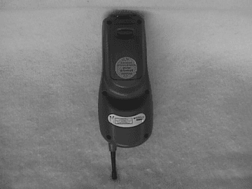
Click to zoom
Application Details
- Equipment Class
- TNB - Licensed Non-Broadcast Station Transmitter
- Date of Grant
- Mar 14, 2001
- Application Purpose
- Original Equipment
- Date of Application
- Jan 18, 2001
- Equipment Note
- 7500 Series Family Portable Data Terminal
- Frequency Range
- 824.04000000 - 848.97000000
- Company
- Symbol Technologies Inc
- Country
- United States
Documents & Files
Document Text
Text extracted from the exhibit documents filed with the FCC. Open a document above to read the original.
Users Manual
Regulatory Addendum: 1)WARNING-FCC RF EXPOSURE GUIDELINES To satisfy FCC RF exposure compliance requirements for a portable transmitting device, this device should be used in hand-held, hand-operated configurations only. The device and its antenna should generally maintain a separation distance of 20 cm or more from a person's body; except for the hands and wrists because of higher exposure limit for extremities. This device is designed to be used in a person's hands and its operating configurations, generally do not support normal transmissions while it is carried in pockets or holsters next to a person's body. The following statement is presently being added to the QRG (Quick Reference Guide –User’s Manual) for the Symbol Diamond Terminal line. This addition will be covering the PDT 7532 CDPD, PDT 7533 CDPD/AMPS and PDT 7530 Datatac. Sandy Mazzola Symbol Technologies Inc 1 Symbol Plaza Holtsville, N.Y. 11742-1300 Phone: (631) 738-5373 Fax: (631) 738-3915 or (631) 738-3318 E-mail: [email protected]
Users Manual
PDT 7500 Series PDT 7500 Series 1999-2000 SYMBOL TECHNOLOGIES, INC. All rights reserved. Symbol reserves the right to make changes to any product to improve reliability, function, or design. Symbol does not assume any product liability arising out of, or in connection with, the application or use of any product, circuit, or application described herein. No license is granted, either expressly or by implication, estoppel, or otherwise under any patent right or patent, covering or relating to any combination, system, apparatus, machine, material, method, or process in which Symbol products might be used. An implied license only exists for equipment, circuits, and subsystems contained in Symbol products. Symbol is a registered trademark of Symbol Technologies, Inc. Other product names mentioned in this manual may be trademarks or registered trademarks of their respective companies and are hereby acknowledged. Symbol Technologies, Inc. One Symbol Plaza Holtsville, N.Y. 11742-1300 http://www.symbol.com Patents This product is covered by one or more of the following U.S. and foreign Patents: U.S. Patent No.4,387,297; 4,460,120; 4,496,831; 4,593,186; 4,603,262; 4,607,156; 4,652,750; 4,673,805; 4,736,095; 4,758,717; 4,816,660; 4,845,350; 4,896,026; 4,897,532; 4,923,281; 4,933,538; 4,992,717; 5,015,833; 5,017,765; 5,021,641; 5,029,183; 5,047,617; 5,103,461; 5,113,445; 5,130,520; 5,140,144; 5,142,550; 5,149,950; 5,157,687; 5,168,148; 5,168,149; 5,180,904; 5,216,232; 5,229,591; 5,230,088; 5,235,167; 5,243,655; 5,247,162; 5,250,791; 5,250,792; 5,260,553; 5,262,627; 5,262,628; 5,266,787; 5,278,398; 5,280,162; 5,280,163; 5,280,164; 5,280,498; 5,304,786; 5,304,788; 5,306,900; 5,321,246; 5,324,924; 5,337,361; 5,367,151; 5,373,148; 5,378,882; 5,396,053; 5,396,055; 5,399,846; 5,408,081; 5,410,139; 5,410,140; 5,412,198; 5,418,812; 5,420,411; 5,436,440; 5,444,231; 5,449,891; 5,449,893; 5,468,949; 5,471,042; 5,478,998; 5,479,000; 5,479,002; 5,479,441; 5,504,322; 5,519,577; 5,528,621; 5,532,469; 5,543,610; 5,545,889; 5,552,592; 5,557,093; 5,578,810; 5,581,070; 5,589,679; 5,589,680; 5,608,202; 5,612,531; 5,619,028; 5,627,359; 5,637,852;5,664,229; 5,668,803; 5,675,139; 5,693,929; 5,698,835; 5,705,800; 5,714,746; 5,723,851; 5,734,152; 5,734,153; 5,742,043; 5,745,794; 5,754,587; 5,762,516; 5,763,863; 5,767,500; 5,789,728; 5,789,731; 5,808,287; 5,811,785; 5,811,787; 5,815,811; 5,821,519; 5,821,520; 5,823,812; 5,828,050; 5,850,078; 5,861,615; 5,874,720; 5,875,415; 5,900,617; 5,902,989; 5,907,146; 5,912,450; 5,914,478; 5,917,173; 5,920,059; 5,923,025; 5,929,420; 5,945,658; 5,945,659; 5,946,194; 5,959,285; 6,002,918;D305,885; D341,584; D344,501; D359,483; D362,453; D363,700; D363,918; D370,478; D383,124; D391,250; D405,077; D406,581; D414,171; D414,172, D419,548. Invention No. 55,358; 62,539; 69,060; 69,187 (Taiwan); No. 1,601,796; 1,907,875; 1,955,269 (Japan). European Patent 367,299; 414,281; 367,300; 367,298; UK 2,072,832; France 81/ 03938; Italy 1,138,713. rev. 03/00 1 Quick Reference Introduction The PDT 7500 Series family of portable data terminals puts the processing power of a 486 PC in the user’s hand. The terminal uses a rechargeable Lithium-Ion 1400 mAh smart battery, and incorporates pen technology and bar code scanning capability in a key-based terminal. The PDT 7500 ruggedized hand-held terminal combines: • PC-standard architecture (32-bit 486 DX2) •Microsoft ® MS-DOS 6.22 or Windows ® CE OS • Wireless communication capability using Symbol’s wireless LAN technology • An optional integrated Wireless Wide Area Network (WWAN) cellular radio • Integrated laser scanning capability (1- and 2-Dimensional) • 35-key keypad for key input • Touch screen • IrDA-compliant interface for printing and communications. 2 PDT 7500 Series About This Guide This guide provides information on the operation of the PDT 7500 Series terminal. Specifically, the following topics are discussed: •Parts of the PDT 7500 on page 3 •Installing New or Recharged Batteries on page 5 •Operating the PDT 7500 on page 7 •Using the PDT 7500 Keypad on page 10 •Using the Integrated Laser Scanner on page 11 •Host Communications on page 13 •Using the Touch Screen on page 14 •Troubleshooting on page 15. Accessories Each PDT 7500 requires one 1400 mAh Li-Ion battery (p/n 21- 38602-06). The following optional accessories are available from Symbol Technologies: • Additional Li-Ion battery • Stylus for performing pen functions •Single-slot cradle • Four-slot cradle •Vehicle cradle • IrDA compliant printer • UBC 2000 charging adapter • Null modem cable •Holster. 3 Quick Reference Parts of the PDT 7500 Scan Button LCD Power Key Scan LED Front View Communication LED Battery Charge LED Thumb Rest To p V i e w Scan Window 4 PDT 7500 Series Parts of the PDT 7500 (continued) Bottom View Serial Communications Port IrDA Port Back View Battery Latch Li-Ion Battery 5 Quick Reference Installing New or Recharged Batteries Caution: To ensure proper terminal operation, use ONLY the Symbol Li-Ion battery in the PDT 7500. To install a new or recharged Li-Ion battery: 1. Hook the base of the new bat- tery in the top of the battery compartment, then press the into place. 2. Slide the battery latch to se- cure the battery. If the battery latch is not closed, do not operate the terminal, otherwise data may be lost. Caution: Do not expose the battery to temperatures in excess of 140°F (60°C). Do not disassemble, incinerate, or short circuit the battery. Removing the Battery from the Terminal To remove the Li-Ion battery from the terminal: 1. Suspend the terminal’s power. 2. Slide the battery release switch towards the top of the termi- nal until the lock releases. 6 PDT 7500 Series 3. Lift the battery up and out of the battery compartment. Charging the Battery in the Terminal To charge the terminal’s battery, place the PDT 7500 in the cradle or connect the synchronization/charging cable. The terminal’s charging LED turns yellow while charging, then turns green when the batt…
Text truncated - open the document above for the full version.
Attestation Statements
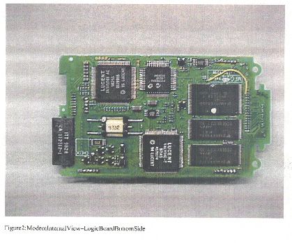
RE: FCC ID H9PPDT7532 Applicant: Symbol Technologies Inc Correspondence Reference Number: 17895 731 Confirmation Number: EA99815 FCC Questions: 1) This application uses a module FCC ID: N7NOEM2 . Since this is an original application, it is FCC policy that the application be complete. The module application cannot be referenced. Please up[load all schematics, internal photos, and test report data for the module. 2) The submitted SAR report contains plots and photos that cannot be read, mostly too dark/black unclear. A report with clear photos that are readable should be re-submitted. 3) The SAR report indicates that the device has been tested in a body-worn holster located at 3 cm from a flat phantom. Please clarify how the 3 cm was measured, preferably with an illustration. Symbol Responses: 1) Very sorry about the confusion. Symbol Technologies Inc. FCC ID H9PPDT7533 contains Sierra Wireless Inc. FCC ID: N7NOEM2, CDPD only device. Symbol Technologies Inc. FCC ID: H9PPDT7532 contains Sierra Wireless Inc. FCC ID: N7NOEM3, CDPD/AMPS device. This device (PDT7532) is the Multi-Mode device containing CDPD and AMPS capability. The exhibits for the original application (FCC ID N7NOEM3 Sierra Wireless Inc) are now included in this upload. Exhibits for block diagram, parts list, schematics, internal photos, external photos and test report data for module are now uploaded in this response. 2) Again very sorry, the original SAR report was very poorly scanned. The report has been rescanned with the highest granularity. The new SAR test report exhibits are uploaded with this submission. 3) The device was located directly butted up against the flat phantom. The 3 cm was the distance from the antenna to the phantom. The holster is designed to be hung on the users belt. From the included photos it can be seen that the belt buckle clip and the design of the terminal when in the holster force the antenna to be the 3 cms away from the flat phantom. No additional distance (3 cms) was added to the testing. The 3 cms distance is as close as the antenna will get to the user when terminal is in the holster. Included other photos show that when holster is on personnel the distance is actually a little more then 3 cms (about 2 inches). This shows that when butted against flat phantom worst case distance is obtained. Belt Clip 3 cm 3 cm antenna to phantom distance caused by Belt clip and terminal face design. No additional spacing was used. Flat Phantom Symbol Terminal
ID Label/Location Info
Sample FCC Label Symbol Technologies Inc. FCC ID: H9PPDT7532 This device complies with Part 15 of the FCC rules. Operation is subject to the following two conditions: (1) this device may not cause harmful interference and (2) this device must accept any interference received, including interference that may cause undesired operation. This is a sample draft of the label that will be located on the underside of the product. Sandy Mazzola
Operational Description
Description Of Differences Symbol Technologies is inserting the Sierra Wireless Inc FCC Part 22 approved CDPD radio module (FCC ID:N7NOEM3) into the Symbol PDT7500 hand held computer terminal. The new product will be known as the PDT7532 Diamond WAN terminal with CDPD/AMPS radio. Symbol is applying for a new FCC ID Number H9PPDT7532. The CDPD/AMPS module itself is being used with no changes at all from the Sierra Wireless Inc. approved unit. The only difference is the cable from module to the antenna and the antenna itself. The antenna is described in another exhibit. Sandy Mazzola Regulatory Engineer Symbol Technologies Inc 1 Symbol Plaza Holtsville, N.Y. 11742-1300 Phone: (631) 738-5373 Fax: (631) 738-3915 E-mail: [email protected]
RF Exposure Info
HOLSTERBUCKLEPHOTOS Holster Buckle JPEG 1 HOLSTERBUCKLE JPEG2 HOLSTERBUCKLE JPEG3 HOLSTERBUCKLE JPEG4 HOLSTERBUCKLE JPEG5 HOLSTERBUCKLE JPEG6 HOLSTERBUCKLE JPEG7 HOLSTERBUCKLE JPEG8 HOLSTERBUCKLE JPEG9 HOLSTERBUCKLE JPEG10 HOLSTERBUCKLE JPEG11
Test Report
Applicant: Symbol Technologies, Inc. FCC ID: H9PPDT7532 Retlif Testing Laboratories Report No.: R-8594-1 GENERAL INFORMATION REQUIREMENTS Paragraph 2.983(a) Name of Applicant:Symbol Technologies, Inc. Address of Applicant:1 Symbol Plaza Holtsville, NY 11742 Name of Manufacturer:Symbol Technologies, Inc Address of Manufacturer:1101 Lakeland Ave Bohemia, NY Paragraph 2.983(b) Equipment Identification:FCC ID: H9PPDT7532 NOTE: This is a change in identification of presently authorized equipment. This device is presently authorized under FCC ID: N7NOEM2 Only those in which the original test results could differ are reported herein, Namely: 2.1046 RF Power Output (ERP method) 2.1053 Field Strength of Spurious Radiation In addition SAR measurements were taken in order to comply with the RF safety requirements. Please refer to SAR.pdf for a full description of SAR testing and results. Applicant: Symbol Technologies, Inc. FCC ID: H9PPDT7532 Retlif Testing Laboratories Report No.: R-8594-1 Paragraph 2.1046 Power Output, Effective Radiated Power Applicant: Symbol Technologies, Inc. FCC ID: H9PPDT7532 Retlif Testing Laboratories Report No.: R-8594-1 POWER OUTPUT, EFFECTIVE RADIATED POWER (Para. 2.1046) A. Measurement Procedure: The transmitter under test was placed on an 80-cm. high non-metallic table on the Open Air Test Site with its antenna polarized vertically. A receive dipole antenna was placed three meters away from the transmitter. The turntable was rotated 360 degrees and the receive antenna was raised and lowered from 1 to 4 meters until a maximum reading was obtained. This reading was recorded. The transmitter under test was replaced with a dipole and signal generator. The signal generator was set to the frequency of the transmitter under test. The level of the signal generator was increased until the level was equal to that previously measured. The required input level from the signal generator in dBm was recorded and converted into milliwatts. This was the Effective Radiated Power of the transmitter. These measurements were recorded for the vertical and horizontal polarizations of the antenna. Setup of the test is shown below: B.Test Results: The results for the above test are submitted as a separate attachment named ERP.pdf. Pre Amp lif ier Spectrum Analyzer Broadband Antenna 3 M 4M Tes t Sa mp le Applicant: Symbol Technologies, Inc. FCC ID: H9PPDT7532 Retlif Testing Laboratories Report No.: R-8594-1 Para. 2.1053 Field Strength of Spurious Radiation Applicant: Symbol Technologies, Inc. FCC ID: H9PPDT7532 Retlif Testing Laboratories Report No.: R-8594-1 FIELD STRENGTH OF SPURIOUS RADIATION (PARA 2.1053) A.Measurement Procedure: The test sample was then placed on an 80cm high wooden test stand which was located three meters from the test antenna on an FCC listed test site. The frequency range scanned was from the lowest frequency generated by the test sample to its tenth harmonic. In order to maximize the level of each emission observed from the test sample, the broadband antenna was tuned to the frequency of each emission and the test sample was rotated 360 degrees. To further maximize the each emission observed, the test antenna was both horizontally and vertically polarized, and then was raised and lowered from one to four meters from the ground plane. The limits for all of the spurious emissions was calculated utilizing the measured output power and the following equation: Limit <dB:V/M> = 20 log [{(49.2 x P T ) ½ /3} x 10 6 ] - (43 + 10 log P T ) The above procedure was performed at the lower, middle and upper frequencies of the device’s range. Setup of the test is shown below: B.Test Results: The results for the above test are submitted as a separate attachment named Spurious RE.pdf. Pre Amplif i Spectr um A l Broadband Antenna 3 M 4M Tes t Sa mp le Applicant: Symbol Technologies, Inc. FCC ID: H9PPDT7532 Retlif Testing Laboratories Report No.: R-8594-1 EQUIPMENT LIST EFFECTIVE RADIATED POWER (ERP) ENTypeManufacture rDe scriptionMode l No.Cal DateDue Date 067Open Area Test SiteRetlif3 MeterRNY10/15/199710/15/2000 141Spectrum AnalyzerHewlett Packard100 Hz - 40 GHz8566B3/20/20009/20/2000 141AGraphics PlotterHewlett PackardN/A7470A3/8/20003/8/2001 141BQuasi-Peak AdaptorHewlett Packard100 Hz - 1 GHz85650A3/20/20009/20/2000 3002Tuned Dipole AntennaEmpire Devices400 MHz - 1 GHzT38/1/19978/1/2000 5414 Watt BBand Amp.ENI500 kHz - 1.0 GHz604L-017/7/19997/7/2000 574Signal GeneratorMarconi Instru.9 kHz - 2.4 GHz20245/1/20005/1/2001 EQUIPMENT LIST Radiated Emissions Spurious, 30MHz-8.5GHz ENTypeManufacture rDe scriptionMode l No.Cal DateDue Date 032AL.P. FilterM icro lab/F XR160 MHz - 400 MHzLA-04N2/29/20002/28/2001 032BL.P. FilterM icro lab/F XR280 MHz - 700 MHzLA-07N2/29/20002/28/2001 032EH.P. FilterM icro lab/F XR1.5 GHz - 3 GHzHD-15N2/29/20002/28/2001 032FH.P. FilterM icro lab/F XR2 GHz - 3 GHzHD-20N7/15/19997/15/2000 032GH.P. FilterM icro lab/F XR3 GHz - 6 GHzHA-30N5/2/20005/2/2001 032HH.P. FilterM icro lab/F XR4 GHz - 8 GHzHD-40N6/21/20004/15/2001 067Open Area Test SiteRetlif3 MeterRNY10/15/199710/15/2000 128CDouble Ridge GuideEaton Corporation1 GHz - 18 GHz960019/16/19999/16/2000 133Broadband Pre-Amplifier Electro-Metrics10 kHz - 1 GHz, 26dBBPA-10006/13/20006/13/2001 141Spectrum AnalyzerHewlett Packard100 Hz - 40 GHz8566B3/20/20009/20/2000 141AGraphics PlotterHewlett PackardN/A7470A3/8/20003/8/2001 141BQuasi-Peak AdaptorHewlett Packard100 Hz - 1 GHz85650A3/20/20009/20/2000 206B6.0 dB AttenuatorTexscan0 - 1.0 GHzFP-50 - 6 dB6/13/20006/13/2001 418L.P. F ilterM ini-C irc uits300 MHzNLP-3002/29/20002/28/2001 523BiconilogElectro-Mechanics26 - 2000 MHz3142B6/8/20006/8/2001 543PreamplifierHewlett Packard1.0 GHz - 26.5 GHz8449B6/16/19996/16/2001 722L.P. F ilterM ini-C irc uits550 MHzNLP-5506/15/20006/15/2001 723H.P. F ilterM ini-C irc uits1000 MHzBHP-10006/15/20006/15/2001
Test Report
TABULAR DATA SHEET CUSTOMER: MODEL No.: TEST SAMPLE: SERIAL No.: TEST SPECIFICATION: TEST METHOD: OPERATING MODE: TECHNICIAN:DATE: RETLIF TESTING LABORATORIES NOTES: DATA SHEETOF JOB No.: PARAGRAPH: Pulsed digitally modulated transmitter. FCC ID:H9PPDT7532 R-8594-1 The EUT was placed on a tabletop, and the radiated output level was measured with a biconilog antenna. After the level was maximized, the EUT was replaced with a dipole and a signal generator. The level of the generator was raised until it matched the level recorded from the EUT. 147.9 120.2 208.9 186.2 295.1 56.2 21.7 20.8 23.2 22.7 24.7 17.5 2.2 2.2 2.2 2.2 2.2 2.2 19.5 18.6 21.0 20.5 22.5 15.3 93.3 90.1 93.6 90.9 94.6 86.6 V/1.8 H/1.8 V/1.8 H/1.0 V/1.8 H/1.3 LOW LOW MID MID HIGH HIGH 600 | | | | | | | | | | | | | V 828.1 828.1 837.0 837.0 847.5 847.5 mWattsmWattsdBmdBdBmdBuVMHz Converted Reading Corrected ReadingMeter Reading Signal Gen. Output Level LimitAntenna Gain Antenna Orientation ChannelCenter Frequency CONTINUOUSLY TRANSMITTING A PULSED SIGNAL AT CENTER FREQUENCY/CHANNEL SHOWN BELOW. 2.985FCC PART 2 Peter LanannaJune 29, 2000 POWER OUTPUT, EFFECTIVE RADIATED POWER METHOD, PARAGRAPH 2.985 R-8594-1Symbol Technologies PDT7532N/A 11
Test Report
Retlif Testing Laboratories R Retlif Job Number R-8594-1 Data Sheet 1 of 1 Test Method: Spurious Case Radiated Emissions, 30 MHz to 8.5 GHz, Paragraph 2.1053 Customer: Symbol Technologies Job No. R-8594-1 Test Sample: Hand-held scanner with RF transmitter. FCC ID: H9PPDT7532 Model No.: PDT7532 Serial No. N/A Operating Mode Continuously transmitting at 837 MHz Test Specification FCC Part 2, Paragraph 2.1053, Field Strength of Spurious Radiation Technician: Peter Lananna Date: June 29, 2000 Notes: Test Distance: D=3 M; Limit in dBuV= 20 log{[(49.2 x P) 1/2 /D] x 10 6 } - (43+10 log P); P=Power in Watts Detector: Peak Test Freq. Antenna Pol./Height EUT Orientation Meter Reading Correction Factor Corrected Reading Converted Reading Limit MHz (V/H) / Meters Degrees dBuv dB dBuv/m uv/m uv/m 30.00 16,596 | | 530.5 V/1.1 180 38.0 1.7 39.7 96.6 | | | 730.5 V/1.3 045 49.0 5.5 54.5 530.9 | | | 739.0 V/1.3 045 51.0 5.6 56.6 676.1 | | | 747.5 V/1.3 045 51.0 5.9 56.9 699.8 | | | 1674.0 V/1.0 180 49.1 -2.8 46.3 206.5 | | | 2511.0 V/1.0 180 61.7 3.8 65.5 1883.6 | | | 3348.0 V/1.0 180 54.9 7.9 62.8 1380.4 | | | 4185.0 V/1.0 180 41.6 10.2 51.8 389.0 | | | 5022.0 V/1.0 180 44.6 3.7 48.3 260.0 | | | 5859.0 V/1.0 180 36.0 5.5 41.5 118.9 | | | 6696.0 6.06.0 V/1.0 180 36.0 10.8 46.8 218.8 | | | 7533.0 0 V/1.0 180 36.0 10.0 46.0 199.5 | | | 8370.0 V/1.0 180 36.0 10.3 46.3 206.5 | | | V V 9000.0 16,596 The EUT was scanned from 30 MHz to 8.5 GHz The emissions observed from the EUT do not exceed the specified limits. All emissions not recorded were more than 20dB below the specified limit.
Contact Information
Applicant
Qianlin Zhou(Regulatory Specialist)
Technical Contact
Retlif Testing LaboratoriesThomas J Schneider
[email protected]631-737-1500
795 Marconi Avenue · Ronkonkoma, New York · United States
Non-Technical Contact
Retlif Testing LaboratoriesMichelle White
[email protected]631-737-1500
Technical Specifications
| # | Rule Parts | Frequency Range | Power Output | Emission | Tolerance |
|---|---|---|---|---|---|
| 1 | 22.901(d) | 824.04 MHz - 848.97 MHz | 295.00 mW | 31K5FXW | 2.5000000000 ppm |
Other Applications from Symbol Technologies Inc

H9PCCHUB1
Jun 30, 2015Customer Concierge
Equipment Class
NII - Unlicensed National Information Infrastructure TX
H9PAP7562
May 10, 2015802.11 abgn/ac Access Point
Equipment Class
DTS - Digital Transmission System
H9PTC75AH
Mar 26, 2015Touch Computer
Equipment Class
NII - Unlicensed National Information Infrastructure TX
H9PRA1202
Sep 24, 2014UHF Narrowband Radio Module
Equipment Class
TNB - Licensed Non-Broadcast Station Transmitter
H9PEMG101
Aug 26, 2014802.15.4 Gateway
Equipment Class
DTS - Digital Transmission System